To help the fisherman - bite alarm
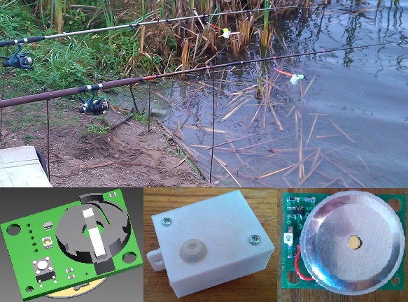
Regularly visiting the nearest bodies of water with a fishing rod and bait, I thought about how to apply the education of an electronics engineer to automate fishing. Fishing rods, echo sounders, boats, bait and much more can be improved and offered to the community of fishermen. It was decided to start with something simple and undoubtedly useful at every workplace of silent hunting. So, in this article you will read about how the bite signaling device was developed.
Donk fishing and bite alarms
I'll tell you in order. The principle of fishing on the donkey is that the bait complete with the bait is placed in a special feeder and the fishing rod is thrown into the water, where it lies at the bottom. Floats are not used, instead of them an indicator is put on the fishing line - sliver, bell, light bulb, etc. When the fish pecks, it pulls the fishing line and the indicator moves. The fisherman picks up a fishing rod and reels in a fishing line, at best - together with the fish. Sometimes the indicator is worn on a fishing rod, which fluctuates with a bite. The evolution of indicators began with wooden pegs fixed to the fishing line, then they were replaced by bells. A little later, devices glowing with chemical or LED light appeared. Now the market is full of Chinese devices that, when bite, produce sound and light signals at the same time. One of the advantages of electronic signaling devices is that they continue to squeak and blink for some time after the bite is over, giving the fisherman more chances to notice it if he turns away or just gaps. As a rule, indicators are placed on the rod or stationary on special pegs. The principle of operation of such devices is based on the capture of fishing rod vibrations or fishing line movements. An important point: there are practically no (I have never seen) electronic devices that are directly attached to the fishing line as pegs or bells were previously attached. The principle of operation of such devices is based on the capture of fishing rod vibrations or fishing line movements. An important point: there are practically no (I have never seen) electronic devices that are directly attached to the fishing line as pegs or bells were previously attached. The principle of operation of such devices is based on the capture of fishing rod vibrations or fishing line movements. An important point: there are practically no (I have never seen) electronic devices that are directly attached to the fishing line as pegs or bells were previously attached.
Along with the evolution of indicators, their fixtures evolved. It ended with the appearance of a universal suspension, worn on a fishing line, in which you can insert Chinese bells or LEDs. Own experience and communication with fishermen colleagues suggested that not everything was invented and improved.
So, we denote the living space of the proposed design: a light-sound indicator will be developed, worn directly on a fishing line or inserted into a Chinese suspension. If such things already exist, then I will not be upset, since it is simply interesting to work in this direction.
The principle of operation and the choice of element base
I came up with several designs that can be used as the basis for the detector:
- piezo signaling device. The piezo element experiences vibrations, is deformed and generates tension. This principle is used in many alarms, for example, automobile;
- movable magnet combined with a Hall sensor. The element oscillates, the sensor picks it up, the signaling device works;
- the same, only with LED and photosensor;
- sensor with reed switch and movable magnet.
I decided to stay on the first option. The piezo element is good in that it generates stress during deformation, and if voltage is applied to it, on the contrary, it deforms and at the same time makes a sound.
That is, it turns out the sensor and tweeter in one bottle, an obvious saving in space and weight. It remains to choose a specific model tweeter. To do this, I went to the nearest radio store and bought all the available models.
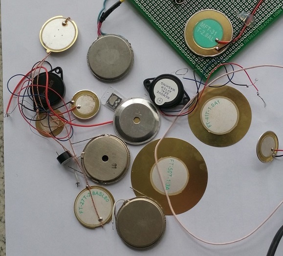
Among all the variety, it was necessary to find the loudest and most sensitive tweeter that would work on battery power. It is important to note that in order for the squeaker to make sounds, it is necessary to apply voltage to it, oscillating with a frequency of the order of several kilohertz. To get this voltage, I planned to use a special device, “a signal generator of a special shape,” but it just broke, I also had the idea to take the voltage from the sound card, but in the end I decided to solder the generator on the breadboard, and immediately debug the squeaker and the circuit as a whole . After a short search on the Internet, several variants of multivibrator and single-vibrator circuits on logical integrated circuits were found, they were slightly modified and as a result, a circuit containing both a single vibrator and a multivibrator was obtained. The single-shot starts up for a few seconds after receiving a signal from the piezo sensor (tweeter). While turned on, it supplies voltage to the multivibrator, which generates oscillations with a frequency of 1-5 kHz and thereby causes the tweeter to make sounds. After a while, the single-shot turns off, the circuit calms down and goes into standby mode. Such a bite detector circuit can be assembled from fairly simple and cheap components. But, being embodied in a real device, it is difficult to change, and this is its main drawback. However, the circuit board was soldered, it is shown in the following figure. In addition to logic elements, it also has a battery compartment and an operational amplifier (AD822), which is needed to increase the signal from the piezo sensor if it turns out to be too small. which generates oscillations with a frequency of 1-5 kHz and thereby causes the tweeter to make sounds. After a while, the single-shot turns off, the circuit calms down and goes into standby mode. Such a bite detector circuit can be assembled from fairly simple and cheap components. But, being embodied in a real device, it is difficult to change, and this is its main drawback. However, the circuit board was soldered, it is shown in the following figure. In addition to logic elements, it also has a battery compartment and an operational amplifier (AD822), which is needed to increase the signal from the piezo sensor if it turns out to be too small. which generates oscillations with a frequency of 1-5 kHz and thereby causes the tweeter to make sounds. After a while, the single-shot turns off, the circuit calms down and goes into standby mode. Such a bite detector circuit can be assembled from fairly simple and cheap components. But, being embodied in a real device, it is difficult to change, and this is its main drawback. However, the circuit board was soldered, it is shown in the following figure. In addition to logic elements, it also has a battery compartment and an operational amplifier (AD822), which is needed to increase the signal from the piezo sensor if it turns out to be too small. Such a bite detector circuit can be assembled from fairly simple and cheap components. But, being embodied in a real device, it is difficult to change, and this is its main drawback. However, the circuit board was soldered, it is shown in the following figure. In addition to logic elements, it also has a battery compartment and an operational amplifier (AD822), which is needed to increase the signal from the piezo sensor if it turns out to be too small. Such a bite detector circuit can be assembled from fairly simple and cheap components. But, being embodied in a real device, it is difficult to change, and this is its main drawback. However, the circuit board was soldered, it is shown in the following figure. In addition to logic elements, it also has a battery compartment and an operational amplifier (AD822), which is needed to increase the signal from the piezo sensor if it turns out to be too small.
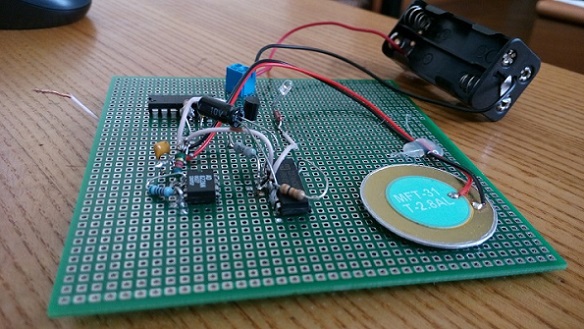
After testing various piezo sensors, the element MFT-31T-2.8 was selected. It turned out to be the most sensitive - during fluctuations with a period of 1-2 Hertz and an amplitude of 5-15 cm, a voltage of about one volt is generated. The sound he made also pleased. In any case, the sound in the room seemed rather loud. Other elements produced less voltage, on the order of several hundred millivolts. And in terms of sound, they were slightly superior or slightly inferior.
Having decided on the piezo element, I proceeded to the selection of other components of the device. The decision to use the logical elements OR-NOT / AND-NOT as a control part impressed with its simplicity and low cost. Honestly, I did not know how else to collect a penny scheme and already even began to prepare this for production. But then the PIC10F220T microcontroller caught my eye. Owners of smartphones, computers and tablets will be interested to know that there are devices with the following characteristics:

This chip is ideal for bite alarms: small size, low power consumption, the necessary peripherals on board, including an ADC and a timer. All this at a price of $ 0.5. Changing the software, you can experiment and bring to mind the functional part, which means that the device receives the design flexibility that is so necessary for new developments. Without hesitation, I replaced the logic chips with this microcontroller. The only thing left is to decide on the power source. A battery with a charge circuit and a connector on the board would complicate the design too much. Just in case, I flipped through several catalogs of radio components. The popular 2032 batteries were pleasantly pleased - 3V voltage with a capacity of 210 mAh. It is easy to calculate that a microcontroller that consumes 100 nA in sleep mode can fall asleep from such a battery, winter and spring, in general, the whole break between the fishing seasons. In working mode, she also promised to serve more than one fishing trip. The voltage level allowed the microcontroller and other structural elements to work. Given the penny cost of these batteries, it was decided to use them. In addition, suitable KLS5-CR2032-03 mounts were selected, from which the battery, after a full discharge, is easily removed and replaced with a new one. In general, the cost of components is $ 5-7. Having adopted the indicated element base, I developed a circuit diagram and turned to a familiar designer of printed circuit boards. After some discussion and oral presentation of the technical specifications, a printed circuit board was designed and then manufactured, which was eventually used in the first prototypes. In working mode, she also promised to serve more than one fishing trip. The voltage level allowed the microcontroller and other structural elements to work. Given the penny cost of these batteries, it was decided to use them. In addition, suitable KLS5-CR2032-03 mounts were selected, from which the battery, after a full discharge, is easily removed and replaced with a new one. In general, the cost of components is $ 5-7. Having adopted the indicated element base, I developed a circuit diagram and turned to a familiar designer of printed circuit boards. After some discussion and oral presentation of the technical specifications, a printed circuit board was designed and then manufactured, which was eventually used in the first prototypes. In working mode, she also promised to serve more than one fishing trip. The voltage level allowed the microcontroller and other structural elements to work. Given the penny cost of these batteries, it was decided to use them. In addition, suitable KLS5-CR2032-03 mounts were selected, from which the battery, after a full discharge, is easily removed and replaced with a new one. In general, the cost of components is $ 5-7. Having adopted the indicated element base, I developed a circuit diagram and turned to a familiar designer of printed circuit boards. After some discussion and oral presentation of the technical specifications, a printed circuit board was designed and then manufactured, which was eventually used in the first prototypes. Given the penny cost of these batteries, it was decided to use them. In addition, suitable KLS5-CR2032-03 mounts were selected, from which the battery, after a full discharge, is easily removed and replaced with a new one. In general, the cost of components is $ 5-7. Having adopted the indicated element base, I developed a circuit diagram and turned to a familiar designer of printed circuit boards. After some discussion and oral presentation of the technical specifications, a printed circuit board was designed and then manufactured, which was eventually used in the first prototypes. Given the penny cost of these batteries, it was decided to use them. In addition, suitable KLS5-CR2032-03 mounts were selected, from which the battery, after a full discharge, is easily removed and replaced with a new one. In general, the cost of components is $ 5-7. Having adopted the indicated element base, I developed a circuit diagram and turned to a familiar designer of printed circuit boards. After some discussion and oral presentation of the technical specifications, a printed circuit board was designed and then manufactured, which was eventually used in the first prototypes. Having adopted the indicated element base, I developed a circuit diagram and turned to a familiar designer of printed circuit boards. After some discussion and oral presentation of the technical specifications, a printed circuit board was designed and then manufactured, which was eventually used in the first prototypes. Having adopted the indicated element base, I developed a circuit diagram and turned to a familiar designer of printed circuit boards. After some discussion and oral presentation of the technical specifications, a printed circuit board was designed and then manufactured, which was eventually used in the first prototypes.
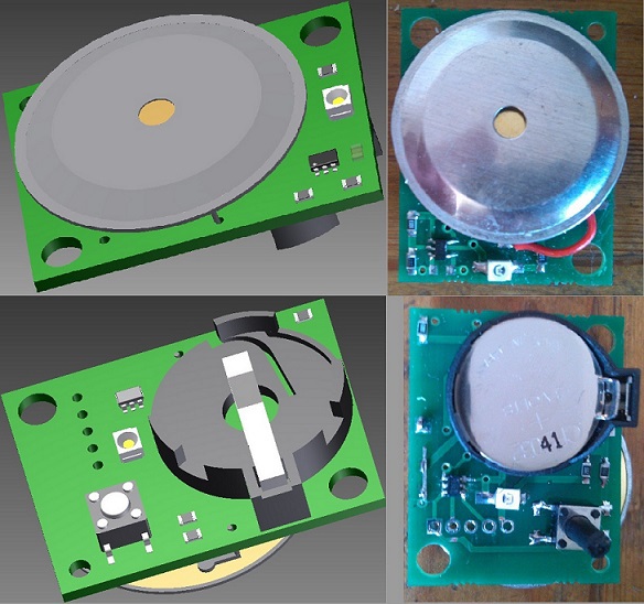
Design and manufacture of housing
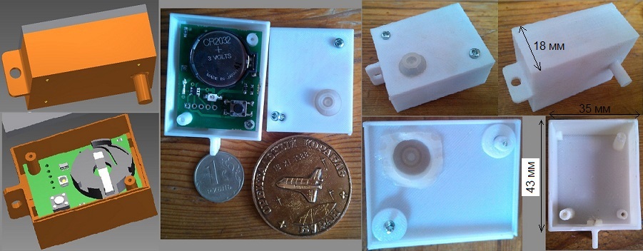
What kind of electronic device without a case and what kind of prototype without a case printed on a 3d printer? For several days the same familiar designer developed the necessary drawings. The housing consists of a base and a cover. The base contains a pin for insertion into a Chinese gimbal (my know-how) and an ear for attachment to a fishing line.
At that time, I still did not know that it was impossible to print a transparent case on the printer. Faced with the harsh realities of 3d first-printers, I had to make the walls of the case thinner so that light from the LED could break through ivory plastic (the only one that was available in the print shop). Having gained experience in the field of 3D printing, a Chinese reprap prusa i3 printer with a kilogram of translucent plastic was purchased for future samples of this and other devices. I hope this will increase the freedom of choice in terms of cases, but at that moment I had to use the services of a third-party manufacturer.
The placement of the LED inside the case is dictated by the requirements of the device's water resistance. Light transmission is ensured by translucency, but what about the controls - the power button and the choice of sensitivity modes? The answer was found in Google. It turns out that in the computer keyboard under the keys there is a special silicone pad. The first keyboard that came across was disassembled, the gasket was removed, and the round wheels were cut out and glued to the body to seal the buttons. The board is attached with screws, just with the addition of rubber gaskets, the cover and the body of the signaling device are connected.
Software
After sending the printed circuit board to production, the software development stage began. The algorithm of operation is quite simple: they pressed a button and the signaling device wakes up, subsequent presses change the sensitivity mode, there are four in total. If the signal from the ADC exceeds a certain threshold value, which means bite, the microcontroller generates an audio signal using a piezo emitter. If the button is pressed for longer than 5 seconds, the device goes into sleep mode. The program came out small and simple, the only difficulty was to fit all the code into the existing 256 bytes of flash memory.
Alarm characteristics
In the end, the board was soldered, the program was written, and the entire device was packed in a case. It's time to bring the characteristics of the alarm:
- dimensions 43 x 35 x 18 mm;
- weight 15g;
- mount on a fishing line or in a suspension;
- 4 sensitivity modes;
- CR2032 battery
- approximately 400 hours before the battery is discharged
- sleep time> 1 year;
- waterproof against rain or spray.
Test
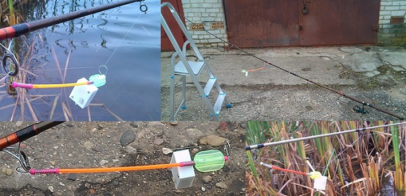
And then came the long-awaited moment of field trials. The end of September, a small pond, non-flying weather. Three donks were abandoned and three indicators were put on alert. Unfortunately, not a single bite happened in a few hours, so I had to imitate them by twitching the fishing line. At the same time, it was possible to evaluate the response of the signaling device to the bite and side rolling under conditions of strong wind, the audibility of the sound and the visibility of the light signals. The sensor showed good sensitivity with small bites, while the response was equally good in different directions of movement of the fishing line. However, a strong side wind rocked the device and also led to its operation. To eliminate the influence of side rolling, it was necessary to reduce the sensitivity, lowering it to the fourth level. Of course at the same time, the reaction to light bites worsened, however, with a strong wind they are, in principle, not noticeable. The audibility of the signal was worse than expected. So, during strong gusts of wind, the sound is practically inaudible already from a distance of two meters, although at home or on a fine day on the street it was perceived loud and sharp. It should be noted that we were in the hoods.
The visibility of the LED was significantly impaired by the opaque housing. At the beginning of fishing, even at dusk, the indication was noticeable, then with the sunrise, I had to look closely to distinguish it. The device contains two LEDs - front and rear, this was done so that the alarm was visible from any angle. After testing, I think about placing both LEDs on the fisherman's side.
It also turned out that it was necessary to change the button operation algorithm. In real conditions - with a strong wind and frozen hands, switching occurs with some emotional effort. Perhaps you should increase the time constant of the contact bounce filter or add a separate on / off button.
Summary
Tests have shown that the bite signaling device, in principle, performs its functions, while some nodes require changes. First of all, I plan to make transparent or translucent cases, change their shape and carefully consider the connection of the base and cover for better moisture protection. A more expensive operation is to increase the volume, since this requires changing the circuit and the circuit board of the device. And finally, the most difficult is the elimination of sensitivity to lateral pitching.
In general, work on the indicator took two months of episodic work or a total of one and a half weeks, not counting substantive communication with the fishermen, which brings only pleasure and, of course, does not go to the general expense.
PS
You can download the drawings and source codes of the alarm program.