Fiasco. The story of one homemade IoT
This is a continuation of my publication Developing smart devices on the example of a floor heating controller on ESP8266
Let's start from afar
I live in a small house that is built according to my project. Layout - eurotreshka, corridor, kitchen-living room on the first floor, bathroom, children's room and bedroom on the second. Of non-standard - walls arbolit, foundation UWB, heating exclusively TP. At the same time, the floors are wooden, on the second floor there is a floating floor, TP - in the slab GVL. On the first floor there are 3 loops of TP pipes (actually one room), on the second one there are also three, but each loop is responsible for one room (bedroom, bathroom, children's room). A wall-mounted gas boiler of 14 kW is responsible for heat. Controls the boiler Chinese programmable weekly wireless thermostat. Every day of the week he has four periods, in each period you can set the desired temperature. Brains on the battery, the relay is hidden. Works great. But I often need more than I have. I wanted room temperature control. I looked at the proposed solutions I did not like anything. And the word "Arduino" caught my eye. And by specialty I am a programmer. And it started ...
Iron
In iron I am not strong. Soldering board is the height of my abilities. But Arduino is such a simple thing that I understood - even with my knowledge of electronics, I am able to make a temperature controller in a house that suits me.
Temperature sensors
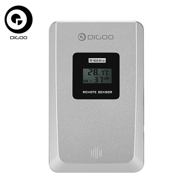
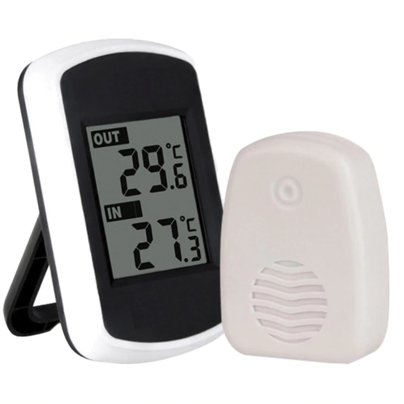
I have no love for wires in the interior. I try to exclude or hide them, if it is impossible to exclude them. And in a somewhat tortuous way, I came to use wireless sensors from Chinese weather stations as room temperature sensors. The sensors operate on batteries for a long time and broadcast at 433 MHz. It is quite nice, you can choose a different color, with the screen and no screen. Looking ahead, I will say that each weather station manufacturer invents its own data transfer protocol with a sensor. During the experiments, I analyzed the protocols of 5 types of sensors - they all have different data transfer formats. I developed a library that accepts data from 4 types of sensors. I didn’t bind with the fifth one - its protocol is not similar to the others by the absence of packet boundaries. The main tool for data analysis has become the Chinese logic analyzer. Without such a tool, it is practically impossible to perform protocol analysis. It is worth quite a bit, it's easy to use - I recommend buying it to all arduinschiki.
I implemented the library on the principle of sampling, frequency 10kHz. This approach allowed to level the noise in the air and reduce the load on the processor, compared with the approach with interruptions when changing the level at the receiver pin. Logic analyzer was used for debugging:
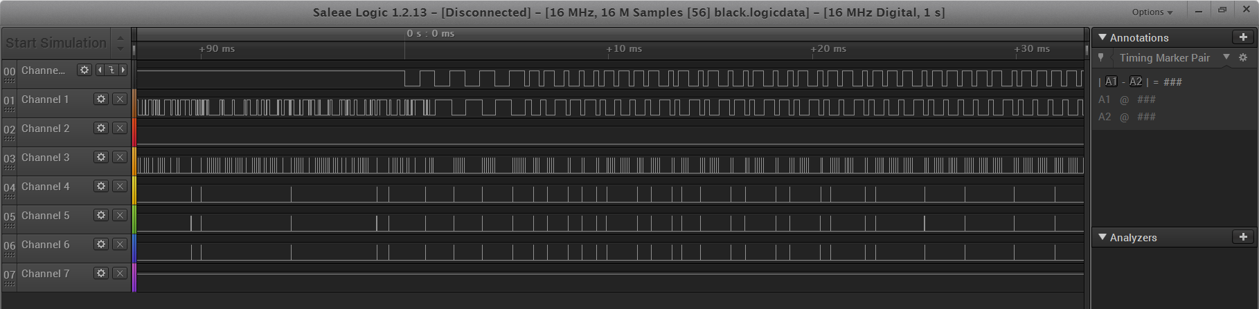
3 ... 6 channels - data for debugging
I will give examples of sensors and their features.
- Type 1: Data transfer every 35 seconds. The period does not change and this is a problem when using 3 or more sensors - the clock in the sensors go a little differently, the signals can sometimes overlap, and one or two sensors fall for an hour or two or three times a week or two. 6 data packets in 0.8 seconds. Sensor ID changes each time it is turned on. No data on battery status.Appearance
 Data
Data
Above - the data of the receiver, the arrows indicate interference
Bottom - the data of the transmitter. - Type 2: Data transmission period - 40 ... 80 seconds, depending on the channel. The best protocol in my opinion is 15 data packets for 0.6 seconds, there is a checksum. Sensor ID changes when turned on, there is a transfer of battery status data. The weakest transmitter - when I put the receiver in the box, the reception quality deteriorated markedly. Probably being treated with an external antenna for the receiver.Appearance
 Data
Data
no interference - Type 3: The data transfer period is 50..55 seconds, depending on the channel. 7 packs for 0.6s. ID changes when turned on, there is a transfer of battery status data. Not a bad choice.Appearance
 DataAlmost identical to type 1
 - Type 4: The data transfer period is 56 ... 76 seconds, depending on the channel. There is no screen. Changeable when enabled ID is not detected. Are there any differences in the ID of different instances - I do not know, I have one such sensor. Data on the status of the battery - is. A powerful signal, the transmission pass was hardly observed.Appearance
 Datanot preserved
 - Type 5: The transmission period is not measured, there is no channel switch, the protocol is not deeply analyzed.Appearance
 Data
Data
As a result, the receiver unit is implemented on the Arduino Pro Mini c output data on the i2c slave.
Arduino mega
This is the first platform on which I made the controller. My controller had a command interface, was controlled by commands entered via UART. At that stage, I planned to make the WEB-interface on ESP8266 and its communication with Mega on the UART. I have a Mega board from Robotdyn, combined with ESP8266, and on this board I was planning to build my own development. A special advantage of the board is a large number of external ports. But in the process of exploring the ESP8266, I realized that this small chip is quite capable of combining the functions of a controller and interface.
ESP8266
I used the WeMos D1 mini board option, it has a small size and a sufficient number of outputs for me - taking into account the use of the port expander. There are a huge number of libraries for this board. For example, me-no-dev / ESPAsyncWebServer is an excellent web server library with web socket support. I gathered the controller on this board. Developed a web interface. Everything works beautifully. But for some incomprehensible reason - uptime is not more than a day. Either I did something crooked, or some of the libraries used is a curve. In addition, there is a limit on 5 simultaneous connections. When exceeded - restart or even hang (despite the existing watchdog. I struggled with hangs using an external watchdog). Given that my web interface consists of almost a dozen files, And browsers load pages in 5 parallel streams - to achieve a restart is elementary. For myself, I decided - this board can only be used as a client. Began to look for other solutions.


ESP32
This is sort of like the heir to ESP8266. In ESP32, most of all - frequencies, memory, legs, ... But the trouble is that the me-no-dev / ESPAsyncWebServer library does not work on it in terms of web sockets. Totally. Flies out. Something related to multithreading. I did not find another web server library with web socket support.
SOC
At this stage, I decided to use a board with linux - I did not invent anything more suitable.
My requirements for the board. It seems there are not many of them:
- I don't need a screen.
- Due to the lack of a screen for initial setup, the board should be able to work in the access point mode.
- I need a minimum of operating system functionality.
Orange Pi i96
This board was suitable in all respects - no video output, WiFi, built-in flash memory, SD card slot. You can put Ubuntu or DietPi on the built-in memory. But the trouble of this board is its software. You can not make an access point. Well, the biggest problem is that when the restart is changed, the MAC address changes and nothing happened with that. In the furnace. (At the time of writing, on w3bsit3-dns.com, in the branch dedicated to the analogue of this board (2g IOT), a message appeared that it is possible to defeat the MAC shift)
Onion Omega 2+
Elegant documentation. With the firmware out of the box, everything started up, the screen is not needed, the UART is optional. SSH is enabled by default. Node.js was installed (version 4.x, but it doesn't matter to me). The sqlite and i2c libraries for Node.js were installed (using a tambourine).
Besides i2c, I no longer need any hardware interfaces. Compared to the version of my development on the ESP8266, a separate Arduino Pro Mini controller has been added to analyze the data of the temperature sensor receiver. The receiver controller is connected to the Omega as an i2c slave. Wired sensors with 1wire interface are connected via a 1wire <-> i2c bridge (DS2482-100). For this bridge there is a library for node.js, but it did not work for me in the part of the search for sensors. I did not understand, ported to DS library js that worked on ESP8266 on js.
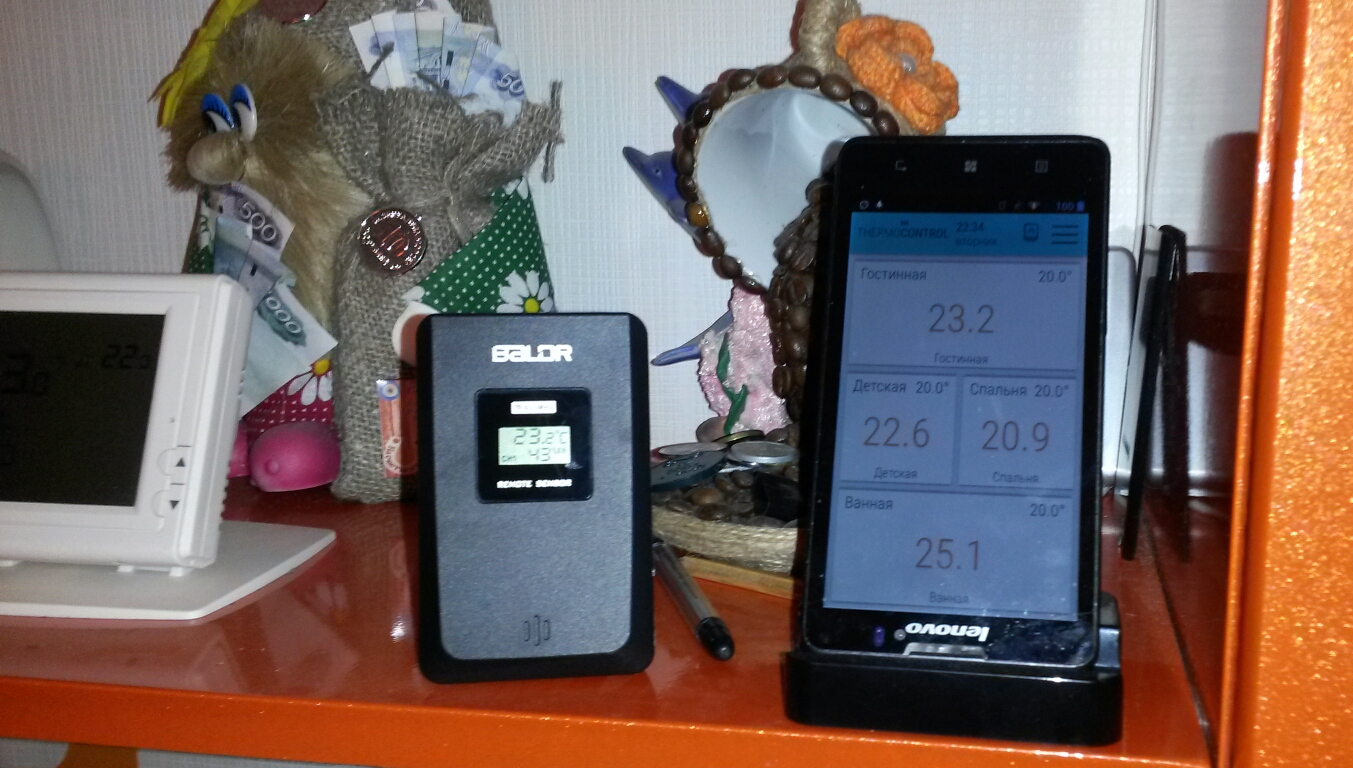
But the trouble is that WiFi on Omega-2 does not work stably, it does not reconnect after rebooting the router. This problem is solved by firmware version 2, it is not in the release status, but it works. It became much better. But the problem was clarified - sometimes the board falls off the Zyxel router and connects again after rebooting the router or after an hour or two or three by itself without rebooting the router. Or it starts terribly stupid - this problem went away after changing the power supply circuit (the board loves 3.3V or slightly higher) and adding an external antenna - the omega was very happy about it. Thus, in principle I am satisfied with the board - something that is not available sometimes does not bother me very much - as the main interface I used an old smartphone in the dock connected to the Omega access point. But remote access will be much needed - I can remotely restart the router. It causes confusion - the Omega-2 has two RST pins - one must be served +, as I understand it, this is handled programmatically. What to submit to the second and how to connect an external watchdog, which gives - I do not know yet.
Controller logic
I have already described the software architecture of the controller — it has not changed (i.e., control of text commands transmitted via a web socket). The web interface migrated from ESP8266 with cosmetic changes. Many procedures / functions of the controller code were simply translated from C ++ to JS. Another thing is that the presence of linux (OpenWRT) gave me the opportunity to use a SQL database - sqlite. Thus, I organized all the logic on SQL queries. This is actually my first experience with sqlite. I especially liked the possibility of using in-memory databases - I arranged all the temporary and current data in this database (for example, sensor data, data on the current required temperature, ...).
Assembly
I collected everything in the gland, placed it in a box. Next - life tests. After a week of uptime - I decided that the test was passed. You can install.

Installation
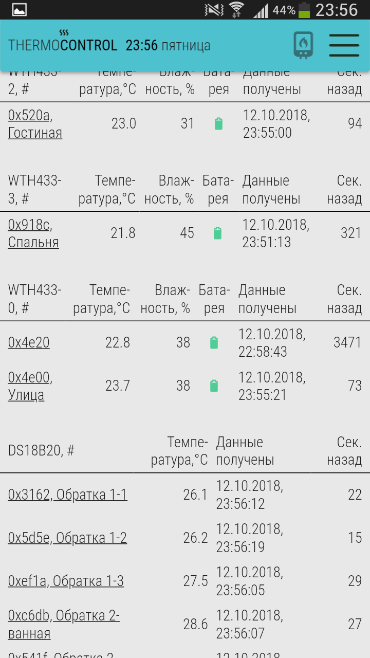
This stage was very successful. Hung a box next to the collector, installed and connected the thermal heads. I was very happy with my idea of storing all data, settings and parameters in the database - on the fly I was able to configure the correspondence of the relays and zones in a way that was not planned, namely, three relays per zone, and all other relays to move (the original the idea was one zone - one relay). The project included the use of a set of DS18B20 service sensors, to monitor the coolant temperature at the supply, in the return pipe of each loop of a warm floor, and the total return temperature - these sensors were also successfully connected and configured (all settings - to specify the clear name of the sensor).
Connected the boiler relay.
Launch
The controller earned as planned.
For the test, I decided to slightly raise the temperature in one of the rooms on the second floor.
The boiler began to overheat and shut down.
And here the service sensors came in handy. It turned out that the water temperature at the exit from the loop of this room is only a couple of tenths of a degree less than at the entrance! The water does not cool! This means that it does not give off heat. And in the whole house it is warm at any temperature overboard (the goal was to slightly lower the temperature on the second floor). So everything gives warmth to the first floor, and the TP on the second floor barely heats the floor. As a result, room-based regulation of heating in such conditions is not possible.
Conclusion
Thus, the influence of physics and the design features of my house put an end to my design. Despite the fact that the controller itself works fine, I cannot use it in the heating system of my house. Maybe I will make him a downgrade, so that he controls the climate in the house like a Chinese thermostat - according to a single sensor, but for now I see no reason.
However, the project as a whole is not successful, in the process of development I became acquainted with many technologies with which I was practically unfamiliar:
- Controller programming
- I learned about the data bus 1wire, i2c, uart, ...
- Gained some knowledge of the web server device
- It seems not bad understood in Web-frontend development: html, JavaScript, vue.js
- I mastered the Web-backend development: node.js
Thus, I got a great experience on a failed project, which may be useful on other projects.
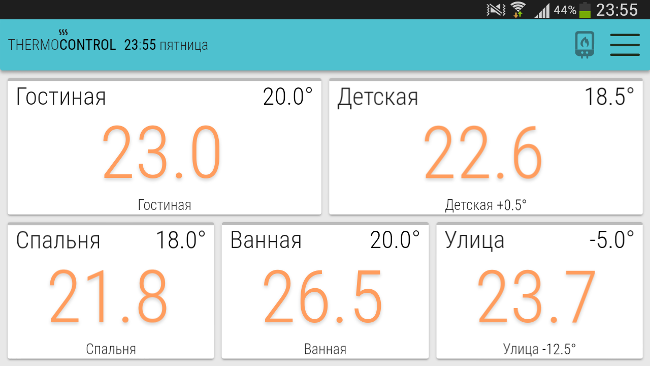
Those who read up to this place - can see what happened .
(the last three settings are blocked)
PS Perfect Board for DIY
In the process of writing the article, another trouble with Omega-2 was discovered - the module began to hang. Hard, reset does not help, just power off. What is the problem - I do not know yet. Maybe he doesn’t like high power - now he receives 3.8V. I'll try to replace the power module. Despite the fact that the project does not fulfill its functions, for the time being I will leave it in thermometer mode (as they say, do not do it on Arduino - you will get a weather station). But in any case, the topic is interesting to me, I want to achieve 100% availability of the system 24/7. If replacing the power supply doesn't help, I'll try the LinkIt Smart 7688 system. It seems to be hardware identical to Omega. It may be more stable.
Addition: after replacing the linear stabilizer 5-> 3.3v with a pulsed problem with WiFi, Onion Omega 2+ was not noticed - stable work for a week. Then he wrote this addition.
Proceeding from this, I haven’t yet found an ideal motherboard for homemade products :(
Probably I’ll try to use a smartphone on android as brains of the next project, I’ll have to connect sensors to it by wifi, but there are almost no problems with the brand phones. And node.
I can put js on the phone, I would be grateful if you share your vision on choosing a board for DIY.