The story of one spacewalk
Creating spaceships is interesting. It is interesting to program autonomous systems - which can land on an asteroid, or enter the orbit of Venus. Space is interesting.
This weekend (April 5), Renewal was dedicated to astronautics . Before that, when I found out that there would be a space theme - I decided to find a 3D model of the Vostok-1 ship, the one on which Gagarin made that historic flight around the Earth - find a model of this ship for printing on a 3D printer - for demonstration to children.
But to my surprise I could not find the descent ...
And perhaps this was for the better, as it led to the independent creation of a model — how to create a spacecraft in an hour in Yekaterinburg, print on a 3D printer in Moscow, present models to a schoolboy and an astronaut at a performance in Digital October, and then create a ship simulator in space and to manage it will be this story.
Theory

Let's recall the theory about space flights. In order for an object to fly in space, it is not enough to lift it up - because the action of gravity will pull him back; he must be given cosmic speed relative to the planet.
Cosmic speed (first v1, second v2, third v3 and fourth v4) is the minimum speed at which a body in free movement from the surface of a celestial body can:
- v1 (circular velocity) - become a satellite of a celestial body (that is, rotate in a circular orbit around a NT at zero or negligible height relative to the surface);
- v2 (parabolic speed, runaway speed) - to overcome the gravitational attraction of a celestial body and go to infinity;
- v3 - leave the star system, overcoming the attraction of a star;
- v4 - leave the galaxy.
For the Earth, the first cosmic velocity v1 = 7.91 km / s. (centrifugal force must be balanced by gravitational force - derived from Newton’s second law). Who cares, the second space velocity - v2 = 11.2 km / s.
Thus, in order for the satellite to enter the Earth’s orbit, it must make a revolution and land:
1. put the satellite into airless space
2. give the first cosmic velocity
3. reduce the speed - so that there would be a fall to Earth
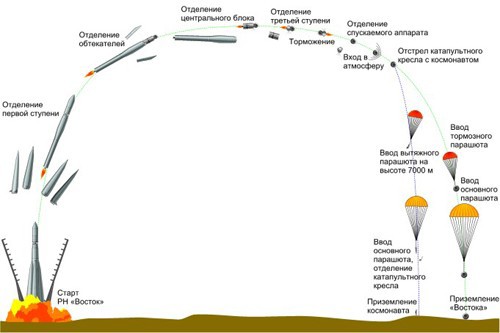
If we give an example of the Vostok rocket, it consisted from launch vehicles (1, 2, 3 stages), and the satellite itself.
Launch vehicle
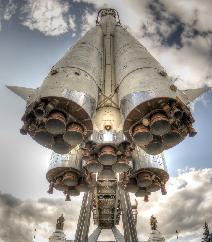
1, 2 - the stages were launched into space (the first stage is the lateral 4 blocks that are separated, the second stage is the central rocket). 3rd stage - clocked the satellite.
Satellite ship
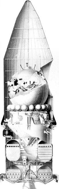
The Vostok spacecraft with the third stage of the launch vehicle under the head fairing.
Flight pattern
The satellite consisted of a descent module (where the astronaut was located), and a braking system with which braking occurred, for an "approach approach". The braking system itself was separated in the upper atmosphere. After that, the descent module was already braked with parachutes.
Now, how did the idea come about.
Idea

When I found out that there would be a “space extension”, I thought that it would not be bad to print on a 3D printer some model connected with astronautics, with the Vostok spaceship.
As I already said - I could not immediately find the model of the Vostok ship in open access. A few days were left before the extension. But what to do if you want to do something - do it yourself :) Looking at the drawing of the ship, I realized that in a simplified form it is a set of primitives: a ball, cone, cylinder.
I printed a picture, and with the help of a ruler I measured the proportions and sizes. This is how the “drawing” turned out%)

To be honest, when I drew the drawing, I vaguely imagined what the satellite ship consisted of, but as I created the model I learned interesting details.
Model creation
To create the model, I used OpenSCAD ( which we once talked about ).
In this system, the 3D model is “programmed” using commands from the openscad language.
Once again I looked at the satellite’s photo - we see that in simplified terms it consists of:
- truncated cone 1 (bottom)
- truncated cone2 (transition to the ball)
- "Beads" of balls around the cone2
- big ball
Making the “foundation”

translate([0, 0, -25])
  cylinder(25, d1=10, d2=56, $fn=10);
Here, a cylinder is drawn with a height of 25, where the diameter of the base is 10 and the top 56 (truncated cone).
But since in the original ship’s design there are “petals”, then you can specify $ fn = 10 - this parameter tells how many fragments will be used to draw a circle (in OpenSCAD all surfaces are planes). Thus, our cone consists of 10 surfaces.
And using the translate command, we transfer the figure to the lower plane (above it we will draw the ship further).
Transition to the sphere
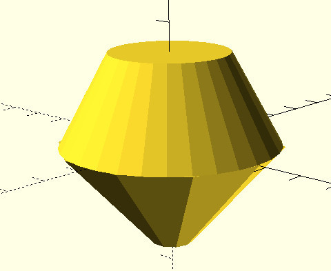
cylinder(23, d1=55, d2=30);
We simply draw a cylinder with a height of 23, a base with a diameter of 55, and an upper base with a diameter of 30.
Sphere
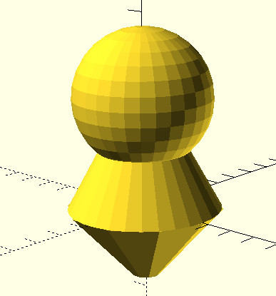
translate([0, 0, 40]){
    sphere(d=50);
}
We draw a sphere with a diameter, and raise it 40 upwards (Z axis).
This is the descent module, it contains the astronaut in the chair. After braking, the sphere detaches from the base.
Beads
"Beads" are containers with gas, serve for the operation of the life support system.
I did not know the exact number, but there were 16 of them.
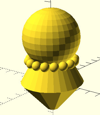
r=20;
for (a = [0:45/2:360-45/2]){
  translate([cos(a)*r, sin(a)*r, 19.5])
  {
    sphere(r=4, $fn=30);
  }
}
To draw the "beads" we use a cycle, and remember the geometry.
If we make a rotation angle of 22.5 degrees (this is 45 in half), then taking the radius, we can place the “balls” around our ship.
We define the variable r = 20 - this is the radius on which our spheres are located.
Take a rotation angle, draw a sphere with a radius of 4. Next, we move it to a point according to the rotation angle and radius. The coordinates are obtained through the cosine and sine of the angle times the radius. And also move up to 19.5.
The loop in OpenSCAD looks like this:
for (ПЕРЕМЕННАЯ = [НАЧАЛЬНОЕ_ЗНАЧЕНИЕ : ШАГ : КОНЕЧНОЕ_ЗНАЧЕНИЕ])And so we go from zero in increments of 22.5 degrees.
Pay attention to the flag $ fn = 30 of the sphere, the smaller it is - the faster your model will render.
Luke
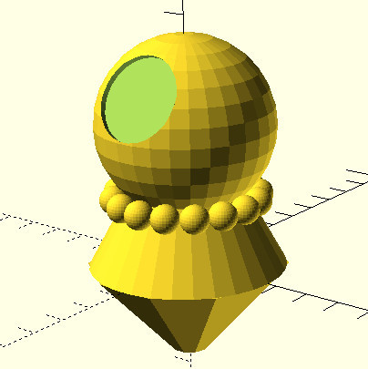
Draw a hatch. In fact, this is not a porthole, it is a hatch through which the astronaut entered the spacecraft at launch, and through which the astronaut planned ejection (in the chair) during descent takes place.
Instead of the line where the sphere was (sphere (d = 50);) it turns out:
  difference(){
    sphere(d=50);
    rotate(a=60, v=[1,0,0]){
      translate([0, 0, 20])
        cylinder(10, 12, 12);
     }
 }
We need to “subtract” the cylinder from the Sphere. To do this, we draw a cylinder with a height of 10, and a radius of 12. Next, we raise it upward by 20 (and since a sphere with a radius of 25, then the cylinder intersects with the surface of the sphere). After that, we rotate the cylinder 60 degrees around the X axis. And after that we execute the difference subtraction command. This command will subtract from the first figure (sphere), the second (cylinder).
Additions
Next, a real hatch was added to the model (through which the astronaut sees the earth), you can also add a clamp holding a sphere, mounting a command cable from the sphere to the module, etc. At the moment, this is of course a very approximate version.
If you experiment in OpenSCAD: a good tip on OpenSCAD commands.
The model (STL + openscad) is laid out onthingiverse and github . In theory, this model can be brought to the level of a DIY constructor.
3D printing
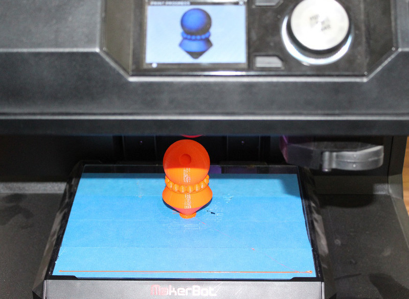
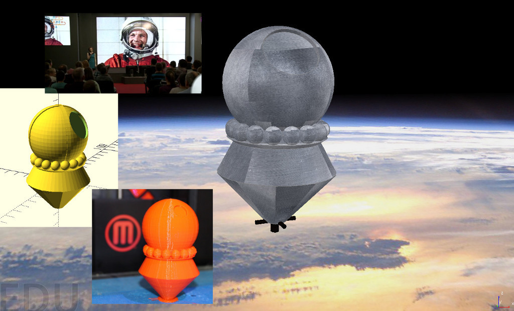
In 3D printing ( as well as the last time ), Ivan from the Moscow Haseysa Neuron ( Laboratory of 3D Printing ) helped . In the photo - the result of printing modelka.
And thanks to the volunteer - the 3D model was brought to Prodlenka.
Extension
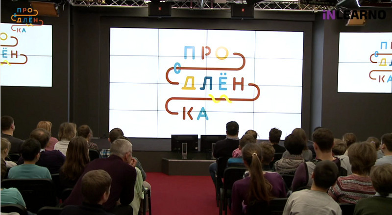
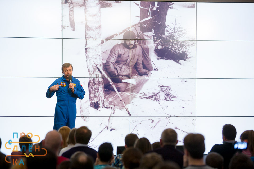
And then came the resurrection of April 5th. The room in Digital October is full of children and parents, the cameras are on and there is a live broadcast to everyone who wants to watch.
Let me remind you the project Prodlenka talks interestingly about the profession. This time it was about the profession of an astronaut .
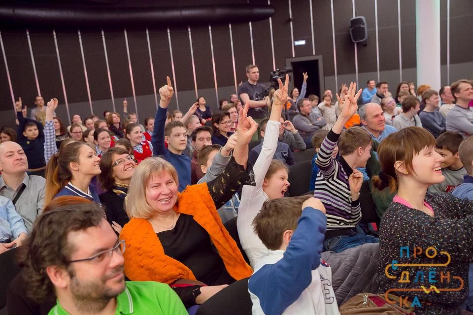
It was an amazing “Renewal” that dad liked almost as much as the kids. Because in every man there lives a boy from the USSR who dreamed of becoming an astronaut. In general, we told a lot of interesting things about Russian cosmonautics. And also about where and how to study, so that if you don’t fly into space in 2020, then at least collect rockets or calculate flights.
Our guest was a real cosmonaut Alexander Ivanovich Lazutkin - flight engineer of the Union TM-25 (184 days in orbit), Hero of the Russian Federation. He opened Prolongka with a story about the profession as a whole and his flight. Then Vitaly Egorov from the private space company Dauria Aerospace explained in detail what you need to know and where to go in order to one day aboard the spacecraft.
Our third guest was Anastasia Stepanova, a space journalist, author of the book “I wish you a good flight ...”. She spoke about the desire for a dream and her journey to space.
On Renewal interesting:


Recording a video broadcast from Renewal you can see here .
But back to our model. Printed 3D models of the Vostok satellite ship were:
- presented for the best question
- presented to astronaut Alexander Lazutkin
Simulator V-REP
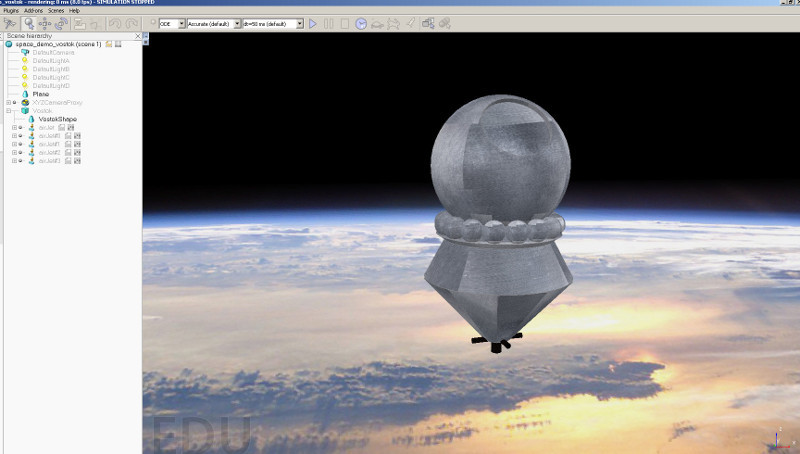
Recently we talked about V-REP - a robotic simulator. And I was wondering if it is possible to simulate systems in it, not only on earth, but also in space.
I decided to try it. And it turned out that gravity is turned off there without problems, the engine supports free flight.
And all that was left for me to do:
- make a background (a photograph of the Earth was found)
- load model (STL model has been loaded)
- add textures (without texture look not very)
- add jet engines (they are built into V-REP
- write management
Perhaps this will be a separate article.
In the process of creation, when I decided where to place the corrective engines, I realized that somehow they would not really look at the skin. But then I looked closely - it turns out they are placed in the tail. There he placed them (in the form of a cross). There is also the main engine.
In the simulator - you can control these corrective engines (arrow keys) and the main engine (space bar). In fact, the main engine was used for braking, and for this the satellite was “turned over” by the engine in the direction of movement (all this was done by automation). But in our case, we can simply “fly” in space on manual control.
Here's a video example: This scene for V-REP can be downloaded from here.

(extension * .ttt).
Other projects on Vostok-1
In the search process, I went to several interesting projects whose authors created or are creating documented reliable flight models of Gagarin (Vostok ship).
Gagarin 3D Project | Gagarin3d.ru
Link: http://gagarin3d.ru
The aim of the project is to create a 3D film about Gagarin's first flight, the most reliable.
For this, a gradual and systematic drawing of all 3D objects occurs. Rendering example from a project:

Dashboard PU-1-3KA. So far, the latest version of the model The texture under the word "Correction" has moved a little bit, there is no factory sign
Flightgear: Vostok-1
Link: http://wiki.flightgear.org/Vostok-1
This is a very interesting project, because This is a full simulator. The author took as a basis the open flight simulator FlightGear . The simulator has the ability to add your planes. But the author added his spaceship. At the same time, having performed the simulation (in total, the project took more than a year).
Here is an example of drawing a part of a satellite ship:

The idea of the project “Gagarin. East"
Against the background of what I saw, I want to propose the idea of the Gagarin.Vostok project.
The essence of the project:
- gathering enthusiasts who are interested in space topics
- gathering factual information on the topic
- directions:
- first launches - autonomous, manned
- Moon
- Venus
- shuttle Buran
- Mars
- other ships
- 3D modeling
issues , - simulation (and programming) issues
- Creation of 3D models for printing, and constructors for assembly.
All information is provided under CreativeCommon formats - open licenses.
This implies the creation of:
- an open discussion group
- creating a place to store projects (github, thingiverse)
- creating an entry point - storing resources (links to participants' sites) - this can be done through githubpages
Having assembled such a group, and showing interest from society - it will be easier to go to the “top” - for cooperation in the design documentation.
References:
- google group
- for aggregation of github projects organization
- start page
The first contribution to this project is the addition of the FlightGear Vostok-1 module .
If you have ideas for those that can be developed further - write. If you are interested and collect facts on Soviet / Russian / international cosmonautics - write.
Message
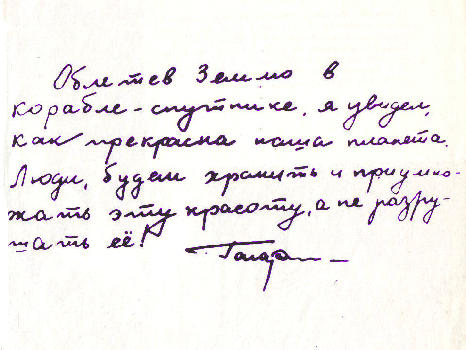
The article was not small, but I cannot but add the words of Yuri Gagarin that he wrote down after his flight into space: