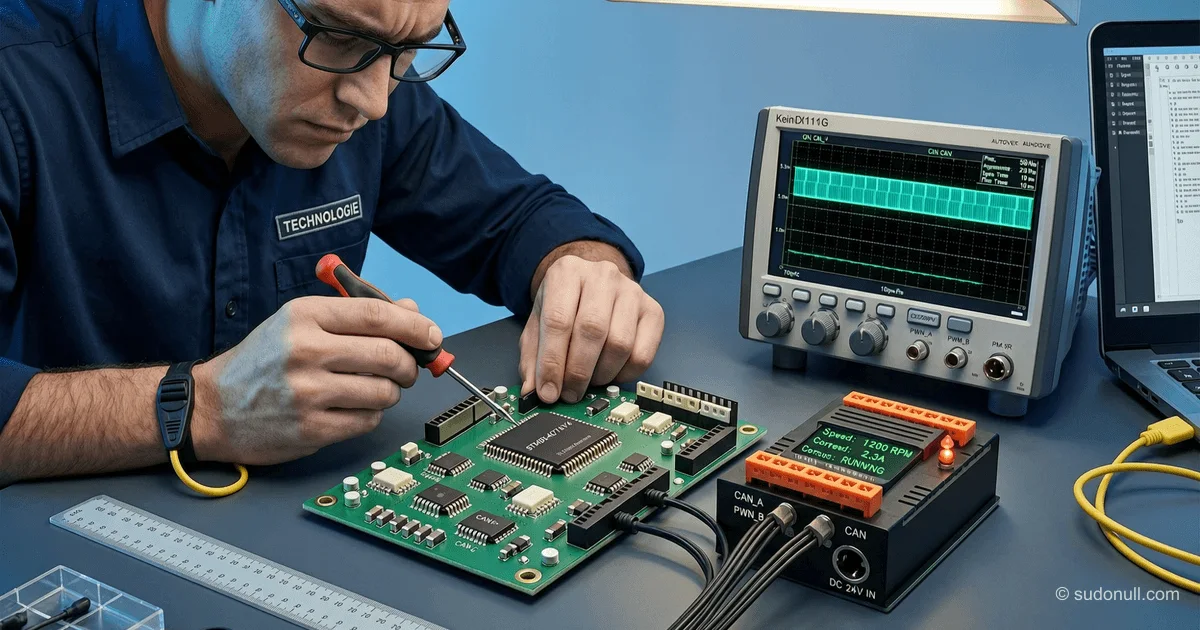
# Implementing CAN Interface in STM32 for Electric Drive Control: Technical Guide
The CAN bus remains the de facto standard for communication in embedded systems with stringent fault-tolerance requirements. Unlike popular UART/I2C interfaces, CAN provides differential data transmission with hardware collision handling via non-destructive arbitration. For projects based on STM32G431RB (as in the IHM03 kit), it's critical to consider the physical layer and data link layer specifics when designing drivers.
Key technical parameters affecting implementation:
- Transmission speed: From 125 kbit/s (Low-Speed) to 1 Mbit/s (High-Speed)
- Network topology: Linear with 120 Ohm terminators at the ends
- Frame format: Standard (11-bit ID) or Extended (29-bit)
- Bit stuffing: Automatic bit insertion after a sequence of 5 identical bits
STM32's embedded CAN controllers (bxCAN) support all operating modes but require precise timing parameter setup (SJW, BS1, BS2). An error in baud rate prescaler calculation will lead to loss of synchronization under high bus load.
Designing the CAN Interface for STM32 Motor Control
Modifying the PMSM Control Project
To integrate CAN into an existing drive control project, the following was required:
- Add the CAN library from STM32CubeMX to the project
- Configure CAN peripheral clocking via RCC
- Implement a ring buffer for receiving/transmitting messages
- Synchronize CAN frame processing with the main motor control loop
A critical aspect is time-sharing between PWM processing and CAN. When using FreeRTOS, a separate task was created with priority higher than the motor control task but lower than safety interrupts.
CAN Database Structure
A DBC-like structure was developed for message management:
typedef struct {
    uint32_t id;
    uint8_t dlc;
    void (*handler)(uint8_t*);
} can_msg_t;

const can_msg_t can_db[] = {
    {0x123, 8, handle_motor_status},
    {0x246, 4, handle_control_cmd},
    // ... other messages
};
Each message is tied to a specific handler function via a dispatch table. This avoided a monolithic switch-case and simplified adding new frame types.
Practical Implementation and Testing
Debugging the Physical Layer
During initial tests, CRC errors were observed due to:
- Incorrect terminator placement (installed only on one end)
- Bus length exceeding limits (over 40 m at 1 Mbit/s)
- Use of unshielded twisted pair
Solution:
- Install 120 Ohm terminators at both ends of the line
- Reduce speed to 500 kbit/s for 60 m length
- Use shielded cable with 120 Ohm impedance
Oscilloscope analysis confirmed the correctness of differential signals (CAN_H=3.5V, CAN_L=1.5V in dominant state).
Load Testing
Stress tests were conducted at 80% bus load:
- Maximum throughput: 700 kbit/s (theoretical limit for 8-byte frames — 750 kbit/s)
- Frame processing latency: < 100 µs
- Error rate: 0 for bus lengths up to 30 m
A critical error occurred during simultaneous transmission of 3 high-priority messages (low ID). It was resolved by configuring CAN_RX filters, separating messages by filter banks.
Key Takeaways
- Bus timing: Precise BS1/BS2 calculations are critical for stable high-speed operation
- Priority arbitration: Low IDs take precedence — plan your message hierarchy in advance
- Error handling: Implement a CAN controller reset mechanism when reaching error passive state
- EMC: Cable shielding and grounding the shield at both ends are mandatory for industrial environments
- Testing: Use CAN analyzers (e.g., PCAN-USB) for protocol verification
Integrating a CAN interface into an STM32 electric drive control project requires deep understanding of both the peripheral's hardware features and protocol specifics. Successful implementation opens the door to distributed control systems with potential integration into IoT platforms and AI analytics.
— Editorial Team










No comments yet.