"Patch" a mirror in the car
A colleague at work bought a new Chery Tiggo FL car, where the Chinese stuffed many different functions for a low cost car. One of the most unusual gizmos in the car turned out to be a “magic” mirror, which is endowed with the functions of a barometer, altimeter and compass.
The main drawback of the entire filling of this vehicle is the lack of temperature sensors behind the vehicle and inside the vehicle. They decided to change this drawback with a colleague by modifying the regular rear-view mirror using non-standard methods.

So, let's start creating a “patch” for the mirror.
Formulation of the problem. It is necessary in the car to receive information about the external ambient temperature and the temperature inside the passenger compartment. As a limitation, we accept that the additional“collective farm”We will not install devices. As an assumption, we take the opportunity to abandon the readings of the altimeter and barometer. The initial data is the rear-view mirror shown in the figure.
Analysis of the source data. Any business begins with the analysis of the source data, so we will start with the dismantling of the mirror and its analysis. Judging by the appearance in the mirror, there are two seven-segment LED indicators of 4 signs, which means either you can get to them, or come up with something of your own.
In general, it is worth noting that the implementation of the functions of the altimeter, barometer and compass is rather disgusting in the mirror, because the readings float strongly, the values are multiples of 100, and the compass is not calibrated by known methods. Therefore, these functions can be thrown out on occasion. Moreover, it is known that the simultaneous measurement of height and pressure with a single barometric sensor is not possible with acceptable accuracy. If the height changes, then the sensor should measure only the height, and if we stand still, we measure only atmospheric pressure. Judging by the readings of the instruments, one gets the feeling that the mirror has one compass and one barometric sensor.
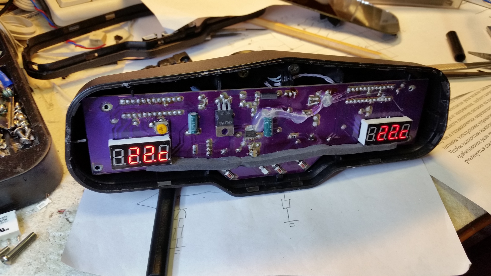
Inside the mirror there is such a board:
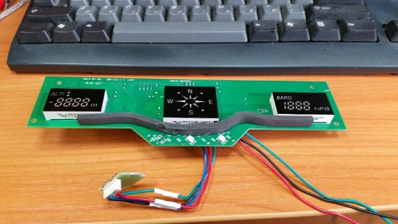
So an autopsy showed that we have a board inside the mirror on which the TM1638 drivers are installed to control the LED indicators, and the logic is wired into the MPC82E54AS2 controller. A MEMSIC C2122M is used as a sensor. So far there is no desire to re-flush the current controller and modify the board, so it was decided to make our own board for the mirror, which will implement our logic and display the information we need from the sensors.
The solution of the problem. So, it was decided to make our own board, repeating the dimensions of the standard board and indicators, just will not use the compass indicator, we do not need it. The logic of the device is as follows:
1) There are three buttons: "+", "PWR", "-": add brightness, turn on or off the backlight, reduce brightness;
2) When the buttons are pressed, the backlight turns on and the information is displayed for 20 seconds;
3) If the screen is on, then PWR turns it off;
4) Temperature data is updated once every 1 second.
Accordingly, the functional diagram of the device has the form:
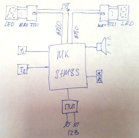
Thus, in accordance with the diagram, the microcontroller interacts with two LED drivers, two temperature sensors via SPI. Everything is powered by a circuit repeating the standard to use part of the radio elements from the board.
We will use STM8S003 as the microcontroller, as the cheapest of the STM8S line, it has enough peripherals, and in particular we only need GPIO, RCC, SPI. As temperature sensors used DS18B20, which do not constitute a deficit and is on hand. For control of LED indicators MAX7221 is used.
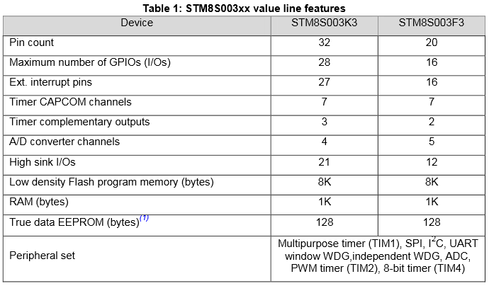
MK STM8S003 has the following characteristics:
The choice of this MK is due to its simplicity, cheapness in a crisis, and the presence of simple development tools (STM8S-Discovery). For those who do not want to breed a signet, you can do the same on a breadboard using the following just a debugging scarf: The

price on ebay is only 120 rubles.
Based on the functional diagram, the following circuit diagram of the device is obtained: A

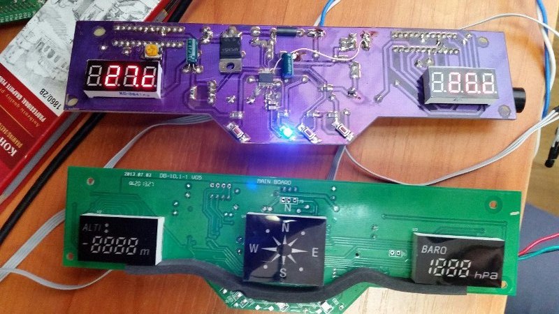
board with two-sided installation was made using photoresist, it also made a layer of a purple mask, which resulted in the following product, a kind of “standard” board and a “patch” board with its own logic:
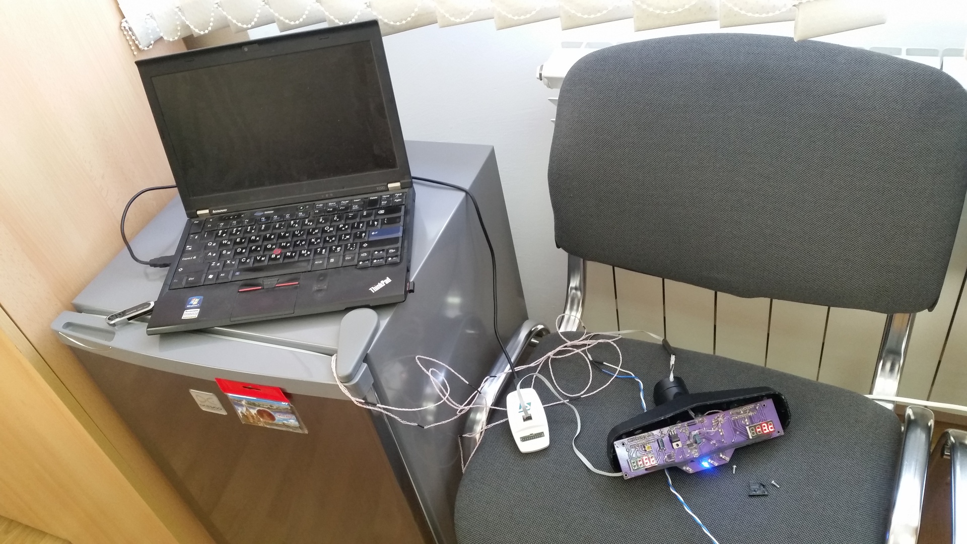
Software implementation quite simple, first worked out on the basis of Arduino, then the functionality was ported to the STM8S combat product, ready for installation on a car. The bench test for climate control and MTBF was successful, so the board is now being installed in the car. When a colleague makes the installation, I will lay out a comprehensive report on all changes in his car.
Inside the source code are three simple C libraries:
From the programming point of view, the key point is the fact that STM8 clocks are floating, so the delays for the DS18b20 are implemented on the base timer 4, for example, the 15 μs delay function for the controller at the frequency of 16 MHz looks like:
An example of an exchange with a DS18b20 sensor using UART1 prompted artko :
The brightness level of the indicators is stored in non-volatile memory according to the principle of "memory card" described using the structure. For each field of the structure there is a function of taking a value and a function of recording a new value.
Conclusions. So, a device has been developed for a car that solves the problem of measuring temperature inside and outside the cabin. It seemed a simple function, but for some reason in Chinese cars it is not, or it is very hidden from the average person.
Demonstration of the functionality of the new board:
Datasheets for the components of the “standard board”:
www.moly-tech.com/uppdf/MEMSIC/MMC2122MG%20RevC.pdf
kazus.ru/datasheets/pdf-data/3675111/MEGAWIN/MPC82E54AS2.html
cholla.mmto.org/computers/ avr / cool_parts / tm1638.pdf
Source code for the firmware of the board:
Source code for IAR
UPD:
As promised, the assembly process in the mirror:
Tests for negative temperatures:
Mirror assembly!
The main drawback of the entire filling of this vehicle is the lack of temperature sensors behind the vehicle and inside the vehicle. They decided to change this drawback with a colleague by modifying the regular rear-view mirror using non-standard methods.
So, let's start creating a “patch” for the mirror.
Formulation of the problem. It is necessary in the car to receive information about the external ambient temperature and the temperature inside the passenger compartment. As a limitation, we accept that the additional
Analysis of the source data. Any business begins with the analysis of the source data, so we will start with the dismantling of the mirror and its analysis. Judging by the appearance in the mirror, there are two seven-segment LED indicators of 4 signs, which means either you can get to them, or come up with something of your own.
In general, it is worth noting that the implementation of the functions of the altimeter, barometer and compass is rather disgusting in the mirror, because the readings float strongly, the values are multiples of 100, and the compass is not calibrated by known methods. Therefore, these functions can be thrown out on occasion. Moreover, it is known that the simultaneous measurement of height and pressure with a single barometric sensor is not possible with acceptable accuracy. If the height changes, then the sensor should measure only the height, and if we stand still, we measure only atmospheric pressure. Judging by the readings of the instruments, one gets the feeling that the mirror has one compass and one barometric sensor.
Inside the mirror there is such a board:
So an autopsy showed that we have a board inside the mirror on which the TM1638 drivers are installed to control the LED indicators, and the logic is wired into the MPC82E54AS2 controller. A MEMSIC C2122M is used as a sensor. So far there is no desire to re-flush the current controller and modify the board, so it was decided to make our own board for the mirror, which will implement our logic and display the information we need from the sensors.
The solution of the problem. So, it was decided to make our own board, repeating the dimensions of the standard board and indicators, just will not use the compass indicator, we do not need it. The logic of the device is as follows:
1) There are three buttons: "+", "PWR", "-": add brightness, turn on or off the backlight, reduce brightness;
2) When the buttons are pressed, the backlight turns on and the information is displayed for 20 seconds;
3) If the screen is on, then PWR turns it off;
4) Temperature data is updated once every 1 second.
Accordingly, the functional diagram of the device has the form:
Thus, in accordance with the diagram, the microcontroller interacts with two LED drivers, two temperature sensors via SPI. Everything is powered by a circuit repeating the standard to use part of the radio elements from the board.
We will use STM8S003 as the microcontroller, as the cheapest of the STM8S line, it has enough peripherals, and in particular we only need GPIO, RCC, SPI. As temperature sensors used DS18B20, which do not constitute a deficit and is on hand. For control of LED indicators MAX7221 is used.
MK STM8S003 has the following characteristics:
The choice of this MK is due to its simplicity, cheapness in a crisis, and the presence of simple development tools (STM8S-Discovery). For those who do not want to breed a signet, you can do the same on a breadboard using the following just a debugging scarf: The
price on ebay is only 120 rubles.
Based on the functional diagram, the following circuit diagram of the device is obtained: A
board with two-sided installation was made using photoresist, it also made a layer of a purple mask, which resulted in the following product, a kind of “standard” board and a “patch” board with its own logic:
Software implementation quite simple, first worked out on the basis of Arduino, then the functionality was ported to the STM8S combat product, ready for installation on a car. The bench test for climate control and MTBF was successful, so the board is now being installed in the car. When a colleague makes the installation, I will lay out a comprehensive report on all changes in his car.
Inside the source code are three simple C libraries:
- work with beeper
- work with LED driver
- work with DS18b20
From the programming point of view, the key point is the fact that STM8 clocks are floating, so the delays for the DS18b20 are implemented on the base timer 4, for example, the 15 μs delay function for the controller at the frequency of 16 MHz looks like:
void _delay_15us(u16 n_15us)
{
   /* Init TIMER 4 */
  CLK_PeripheralClockConfig(CLK_PERIPHERAL_TIMER4, ENABLE);
   /* Предделитель: / (2^3) = 8   /3 */
   TIM4->PSCR = 3;
   /* SYS_CLK_HSI_DIV1 Auto-Reload: 16M / 8 = 2M, тогда 15мкс это 30 тактов */
  TIM4->ARR = 29; // 30 - 1
  /* Компенсация времени инициализации таймера в МК*/
  TIM4->CNTR = 29;
  /* Сбросить флаг обновления */
  TIM4->SR1 &= ~TIM4_SR1_UIF;
  /* Включить счет */
  TIM4->CR1 |= TIM4_CR1_CEN;
  while(n_15us--)
  {
    while((TIM4->SR1 & TIM4_SR1_UIF) == 0) ;
    TIM4->SR1 &= ~TIM4_SR1_UIF;
  }
  /* Отключить таймер */
  TIM4->CR1 &= ~TIM4_CR1_CEN;
  CLK_PeripheralClockConfig(CLK_PERIPHERAL_TIMER4, DISABLE);
}
An example of an exchange with a DS18b20 sensor using UART1 prompted artko :
void ds1820_uartinit(uint32_t baud)
{
  USART_DeInit(USART1);
  USART_Init(USART1, baud, USART_WordLength_8b, USART_StopBits_1, USART_Parity_No,
  USART_Mode_Rx | USART_Mode_Tx);
}
void ds1820_write(uint8_t byte)
{
  UART1->DR = byte;
  while (!(UART1->SR & (uint8_t)UART1_FLAG_TC)); // ждем завершения передачи
}
uint8_t ds1820_read()
{
   return ((uint8_t)UART1->DR);
}
void ds_write(uint8_t byte) {
    int i;
    for(i = 0; i < 8; i ++) {
        if(byte & 1) {
            ds1820_write(0xff);
        } else {
            ds1820_write(0x00);
        }
        ds1820_read();
        byte >>= 1;
    }
}
uint8_t ds_read() {
    int i;
    uint8_t res = 0;
    for(i = 0; i < 8; i ++) {
       ds1820_write(0xff);
       uint8_t c = ds1820_read();
       if(c == 0xff) {
          res |= (1 << i);
       }
    }
    return res;
}
void ds1820_startconversion()
{
  ds1820_uartinit(9600);
  ds1820_write(0xf0);
  ds1820_uartinit(115200);
  ds_write(0xcc);
  ds_write(0x44);
}
int16_t ds1820_readtemp()
{
  ds1820_uartinit(9600);
  ds1820_write(0xf0);
  ds1820_uartinit(115200);
  ds_write(0xcc);
  ds_write(0xBE);
  uint8_t temp1 = ds_read();
  uint8_t temp2 = ds_read();
  int16_t temp3 = (uint16) temp2 * (uint16)0x0100L + (uint16) temp1;
  return temp3;
}
ну и сам сброс
ds1820_uartinit(9600);
ds1820_write(0xf0);
The brightness level of the indicators is stored in non-volatile memory according to the principle of "memory card" described using the structure. For each field of the structure there is a function of taking a value and a function of recording a new value.
Conclusions. So, a device has been developed for a car that solves the problem of measuring temperature inside and outside the cabin. It seemed a simple function, but for some reason in Chinese cars it is not, or it is very hidden from the average person.
Demonstration of the functionality of the new board:
Datasheets for the components of the “standard board”:
www.moly-tech.com/uppdf/MEMSIC/MMC2122MG%20RevC.pdf
kazus.ru/datasheets/pdf-data/3675111/MEGAWIN/MPC82E54AS2.html
cholla.mmto.org/computers/ avr / cool_parts / tm1638.pdf
Source code for the firmware of the board:
Source code for IAR
UPD:
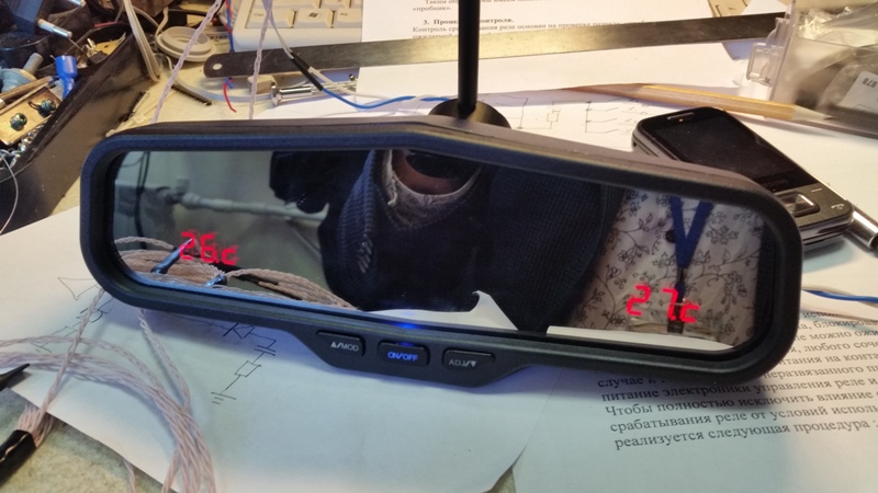
As promised, the assembly process in the mirror:

Tests for negative temperatures:

Mirror assembly!
