Chinese HID programmer USBISP (USBASP) on Linux. Preprogramming
Microcontroller programming and robotics are very promising areas of activity. This is already being said at the state level. It all starts with the fact that beginners collect their first programmer or order it in the online store. The most affordable are Chinese crafts. They are not always ready to immediately please their new owners. However, usually, they are quite functional after completion and / or flashing.
The situation is complicated by the fact that there are many similar models and different versions of Chinese-designed circuit boards. I got programmers with a printed circuit board that is incompatible with the firmware available on the network. Trite, the pin assignment of the microcontroller on the board and in the program does not match. Next, I will describe the treatment process for a small batch of these programmers and some tricks for beginners.
I hope this article will be useful to someone, since there is apparently no information on the Internet specifically for this version of programmers.
For those who want a quick fix, at the end of the article there is a link to the archive with my improved USBASP firmware from Thomas Fischl and a list of changes in git diff format.
I decided for classes in robotics at our Center for Children's Computer Creativity to purchase a set of programmers and microcontrollers. The choice fell on Aliexpress. Cheap and cheerful.
I ordered a pack of Attiny13A, a couple of pads for them, several Atmega32 on the training boards, breadboard models, and, of course, a dozen USBASP programmers. Earlier, I already ordered a couple of similar programmers - one of them even worked.
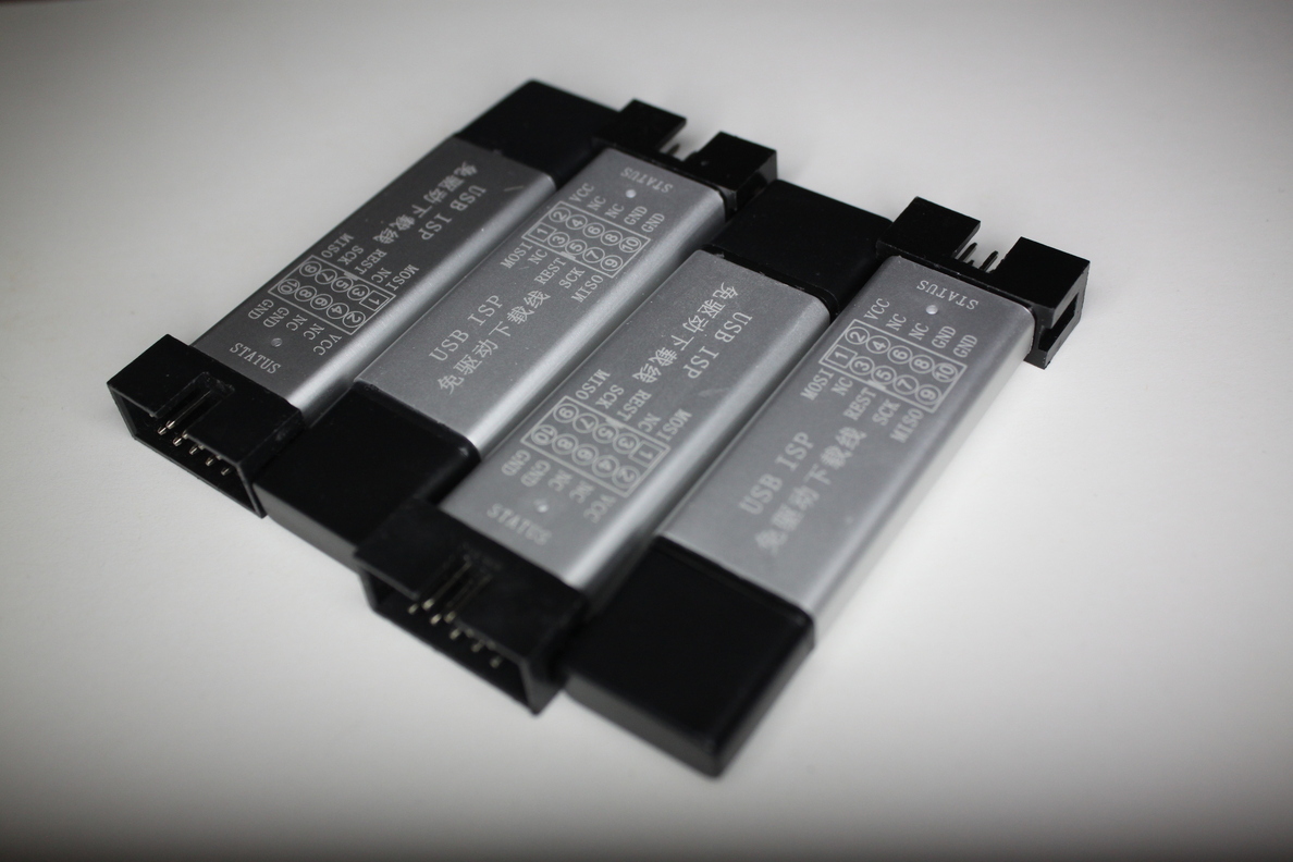
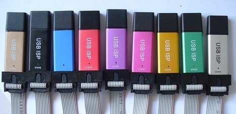
As it turned out, the delivered programmers turned out to be inoperative in Ubuntu Linux. One of them corresponded to the advertising picture, the remaining 9 were slightly longer and were not packed in antistatic bags. At the same time, all 10 were labeled USBISP on the case and proudly identified as a HID device.
Sly Chinese, wanting to simplify life for users of the default OS, wrote firmware that did not require drivers. One minus - with these programmers only one Chinese program can work with an interface in the Chinese language and only in one OS. This option categorically did not suit me.
A network search led me to the Hacking an AVR programmer page .
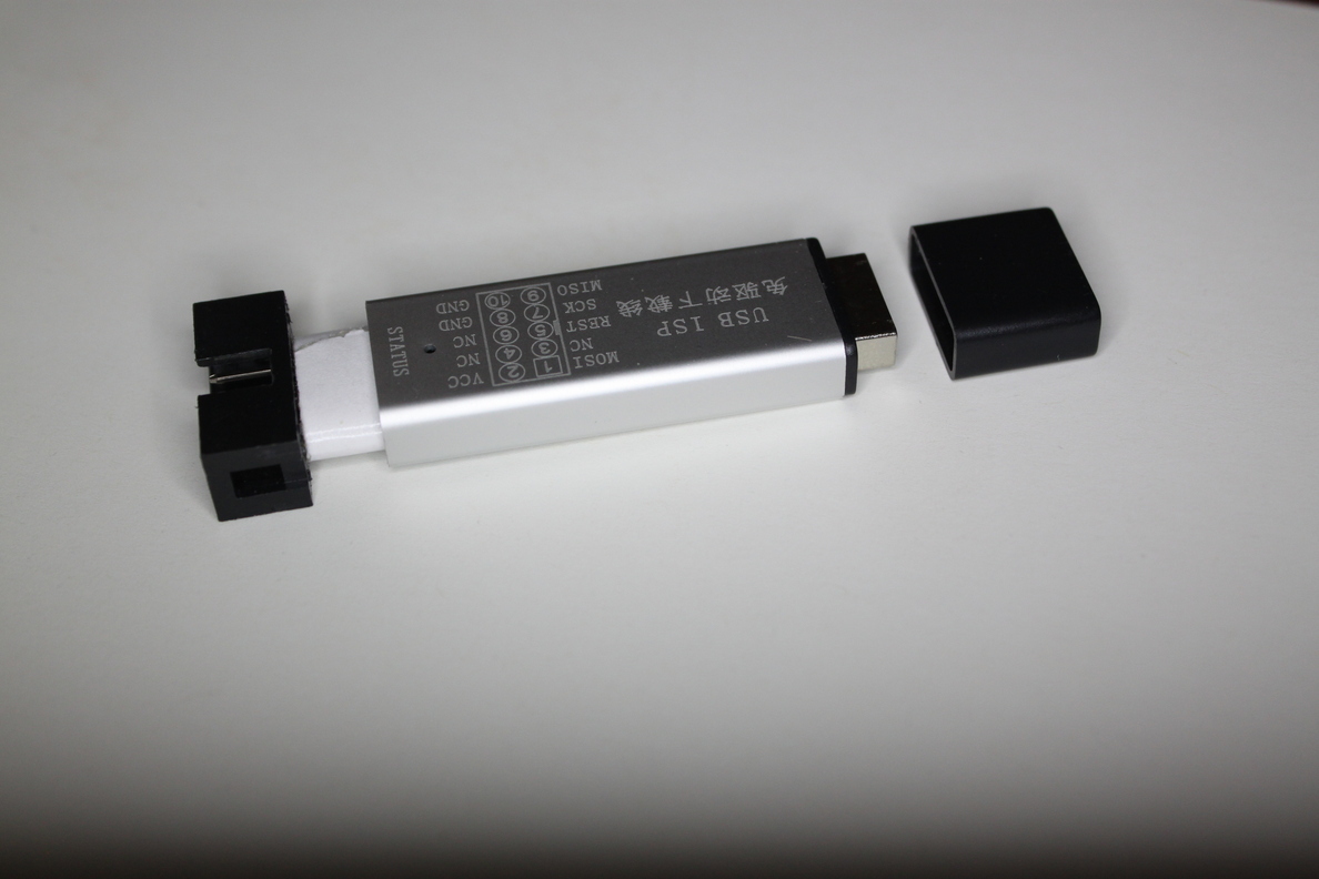
Everything is wonderful and described there. I was delighted and began to disassemble the programmers. It turned out to be easy. Struck by the original design solutions in the form of an insulator from double-sided tape.
I was happy early. On this page, the flashing process for another version of the programmer (v3.0) was described, which is divorced otherwise. I had in my hands an unidentified version of the programmer.
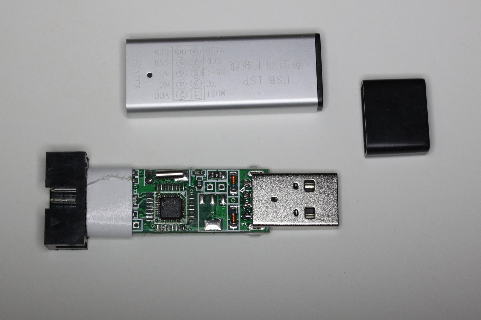
The result of studying the board is the picture below. Everything that was possible was divorced differently than in the already familiar third version with a blue board. This did not stop to finalize the firmware, in which I had to change the pin numbers, their initialization (see article Hacking an AVR programmer) and LED control algorithm.

In the original usbasp firmware, the legs 12.13 and 23.24 are responsible for USB and LEDs. The conclusions of 1.32 and 9.10 were divorced on the board. In this case, the LEDs were connected counter-parallel, which was subsequently taken into account in the program.
There were no jumpers for programming here. Therefore, I had to slightly redo the loop, releasing the “Reset” wiring to the will. I temporarily soldered this wire to the “Reset” input for programming the victim.
Visual picture that helped me in comparing the controller legs (ATmega8):

It’s good that a working programmer was already available. Just version v3.0, but with working firmware.
The first two programmers were flashed successfully. The third protested. It turned out that it was precisely the 29th “Reset” leg that was not soldered.
Having eliminated this jamb, I continued to work.
On the fifth programmer, I was tired of soldering the wiring to the reset, and I applied a less reliable, but faster method. Helped daughter's gum for hair.
The victim programmer is plugged into the USB hub (blue) only to be more stable - the hub is not connected anywhere.
Sometimes I received messages from avrdude that the controller is not responding. The voltage reduction was saved by a three-meter USB extension cable and a decrease in the programming speed (-B switch in the line "avrdude -c usbasp -p m8 -B 50").
Archive with original firmware: www.fischl.de/usbasp/usbasp.2011-05-28.tar.gz
We look in the section “BUILDING AND INSTALLING FROM SOURCE CODE” in Readme.txt
From the archive we extract the folder /usbasp.2011-05-28 / firmware /
Modify the firmware to taste.
In the console, go to the firmware folder and run make to get help on the available commands.
We compile the firmware and fill it into the programmer (through another working programmer).
Archive with modified firmware (source + compiled main.hex firmware): app.box.com/s/xz4neeubv663rvcem12pbctq91hutpp2
Original firmware (USBasp firmware from Thomas Fischl): www.fischl.de/usbasp
Hacking an AVR programmer: www.sciencetronics / greenphotons /? p = 938
An article on the hub on the same topic: "How to get a Chinese USB-programmer for $ 5 to work on Linux"
The situation is complicated by the fact that there are many similar models and different versions of Chinese-designed circuit boards. I got programmers with a printed circuit board that is incompatible with the firmware available on the network. Trite, the pin assignment of the microcontroller on the board and in the program does not match. Next, I will describe the treatment process for a small batch of these programmers and some tricks for beginners.
I hope this article will be useful to someone, since there is apparently no information on the Internet specifically for this version of programmers.
For those who want a quick fix, at the end of the article there is a link to the archive with my improved USBASP firmware from Thomas Fischl and a list of changes in git diff format.
Purchase
I decided for classes in robotics at our Center for Children's Computer Creativity to purchase a set of programmers and microcontrollers. The choice fell on Aliexpress. Cheap and cheerful.
I ordered a pack of Attiny13A, a couple of pads for them, several Atmega32 on the training boards, breadboard models, and, of course, a dozen USBASP programmers. Earlier, I already ordered a couple of similar programmers - one of them even worked.
As it turned out, the delivered programmers turned out to be inoperative in Ubuntu Linux. One of them corresponded to the advertising picture, the remaining 9 were slightly longer and were not packed in antistatic bags. At the same time, all 10 were labeled USBISP on the case and proudly identified as a HID device.
Description of the USBASP USBISP programmer with aliexpress (by the way, about Linux - not a word):
The USBASP USBISP AVR / 51 Series Programmer Download Aluminum Shell No 64K Limit Support WIN7 64
Description:
Perfectly support WIN7
1, support USB1.1 or USB2.0 communication.
2, support WIN98, WINME, WIN2K, WINXP operation system.
3. USB ports Power Supply, power supply output is 500 MA since the recovery, which can effectively prevent outside of USB influence short circuit, target board can supply with USB together.
4, download not finish influence the operation of the target board.
5, support S51 and AVR chips record, speed faster than parallel ISP, more stable; There is no parallel notebook computer and use the best choice.
6, the latest version of exceed stable firmware, download speed jump line without choice, download speed faster, more stable.
7, using standard IDC10 interface
Sly Chinese, wanting to simplify life for users of the default OS, wrote firmware that did not require drivers. One minus - with these programmers only one Chinese program can work with an interface in the Chinese language and only in one OS. This option categorically did not suit me.
Search for a solution
A network search led me to the Hacking an AVR programmer page .
Everything is wonderful and described there. I was delighted and began to disassemble the programmers. It turned out to be easy. Struck by the original design solutions in the form of an insulator from double-sided tape.
I was happy early. On this page, the flashing process for another version of the programmer (v3.0) was described, which is divorced otherwise. I had in my hands an unidentified version of the programmer.
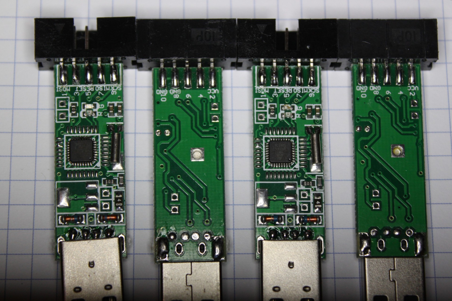
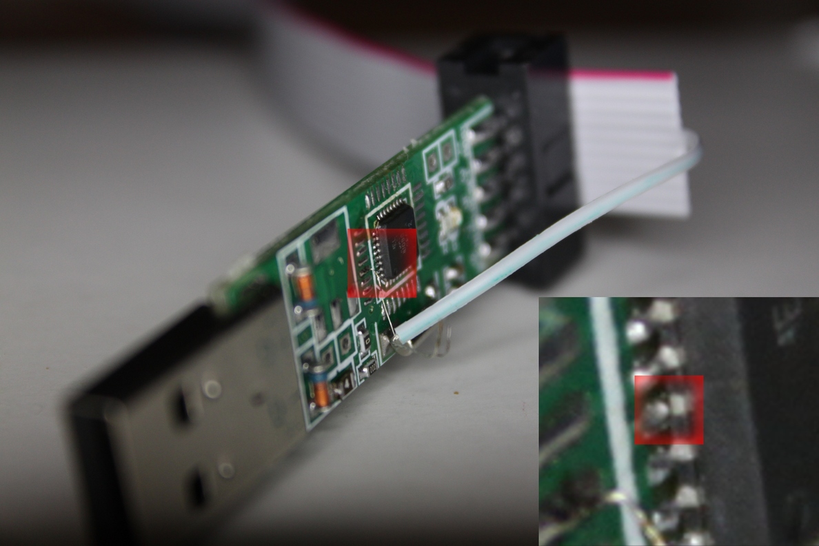
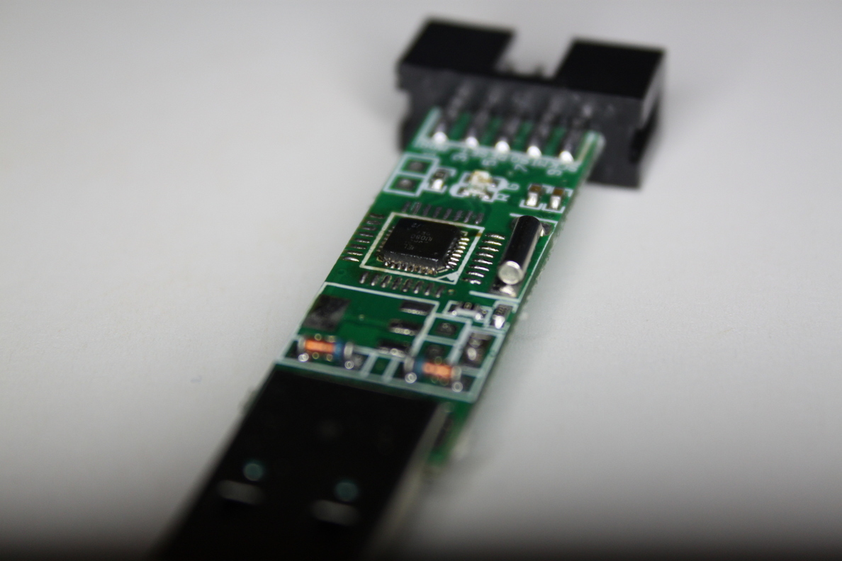
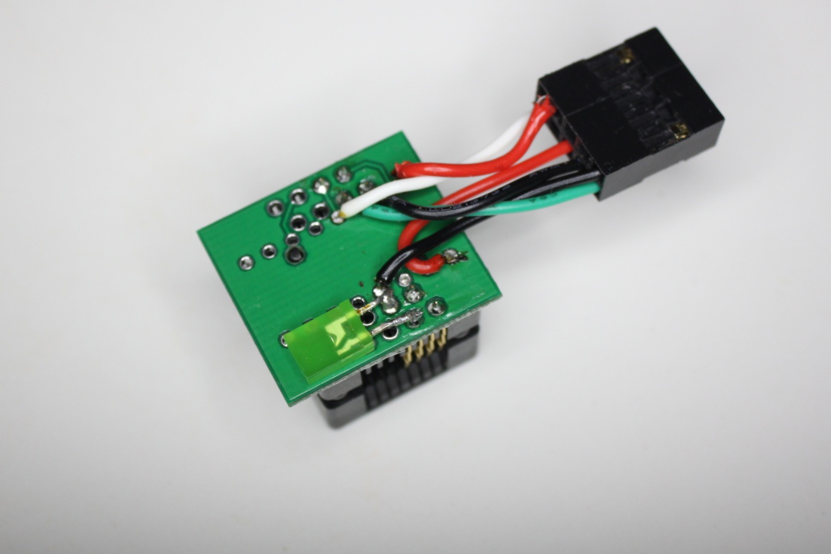
The result of studying the board is the picture below. Everything that was possible was divorced differently than in the already familiar third version with a blue board. This did not stop to finalize the firmware, in which I had to change the pin numbers, their initialization (see article Hacking an AVR programmer) and LED control algorithm.
In the original usbasp firmware, the legs 12.13 and 23.24 are responsible for USB and LEDs. The conclusions of 1.32 and 9.10 were divorced on the board. In this case, the LEDs were connected counter-parallel, which was subsequently taken into account in the program.
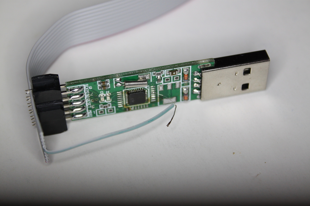
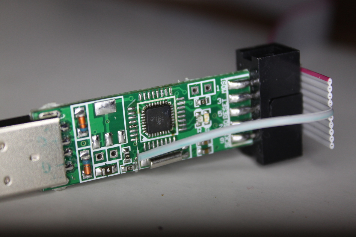
There were no jumpers for programming here. Therefore, I had to slightly redo the loop, releasing the “Reset” wiring to the will. I temporarily soldered this wire to the “Reset” input for programming the victim.
Visual picture that helped me in comparing the controller legs (ATmega8):
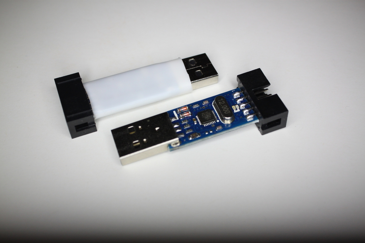
It’s good that a working programmer was already available. Just version v3.0, but with working firmware.
Flashing
The first two programmers were flashed successfully. The third protested. It turned out that it was precisely the 29th “Reset” leg that was not soldered.
Having eliminated this jamb, I continued to work.
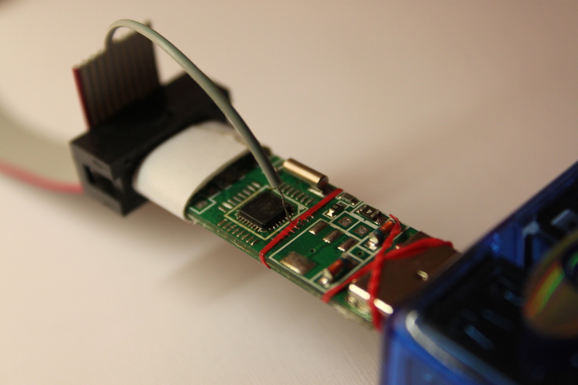
On the fifth programmer, I was tired of soldering the wiring to the reset, and I applied a less reliable, but faster method. Helped daughter's gum for hair.
The victim programmer is plugged into the USB hub (blue) only to be more stable - the hub is not connected anywhere.
Sometimes I received messages from avrdude that the controller is not responding. The voltage reduction was saved by a three-meter USB extension cable and a decrease in the programming speed (-B switch in the line "avrdude -c usbasp -p m8 -B 50").
The most important thing for a snack
Archive with original firmware: www.fischl.de/usbasp/usbasp.2011-05-28.tar.gz
We look in the section “BUILDING AND INSTALLING FROM SOURCE CODE” in Readme.txt
From the archive we extract the folder /usbasp.2011-05-28 / firmware /
Modify the firmware to taste.
In the console, go to the firmware folder and run make to get help on the available commands.
We compile the firmware and fill it into the programmer (through another working programmer).
Git diff for this project (my changes)
diff --git a/main.c b/main.c
index a225432..64755ca 100755
--- a/main.c+++ b/main.c
@@ -306,11 +306,16 @@ int main(void) {
 	/* no pullups on USB and ISP pins */
 	PORTD = 0;
 	PORTB = 0;
+	PORTC = 0;  /* PORTC not connected */
 	/* all outputs except PD2 = INT0 */
-	DDRD = ~(1 << 2); +	//DDRD = ~(1 << 2);
 	/* output SE0 for USB reset */
-	DDRB = ~0; +	// DDRB = ~0; +  //DDRD = ~0; +	DDRD = 0b01100000;  // 1 = output (PD6+PD5 LEDS, PD3+PD2 USB) +  ledRedOff(); +
 	j = 0;
 	/* USB Reset by device only required on Watchdog Reset */
 	while (--j) {
@@ -322,10 +327,9 @@ int main(void) {
 	/* all USB and ISP pins inputs */
 	DDRB = 0;
-	/* all inputs except PC0, PC1 */ -	DDRC = 0x03; -	PORTC = 0xfe; - +  /* PORTC not connected -> all inputs*/ +	DDRC = 0; +
 	/* init timer */
 	clockInit();
diff --git a/usbasp.h b/usbasp.h
index b60bd04..9c12652 100644
--- a/usbasp.h+++ b/usbasp.h@@ -62,9 +62,9 @@
 #define USBASP_ISP_SCK_1500   12  /* 1.5 MHz   */
 /* macros for gpio functions */
-#define ledRedOn()    PORTC &= ~(1 << PC1)-#define ledRedOff()   PORTC |= (1 << PC1)-#define ledGreenOn()  PORTC &= ~(1 << PC0)-#define ledGreenOff() PORTC |= (1 << PC0)+#define ledRedOn()    PORTD |= (1 << PD5); PORTD &= ~(1 << PD6)+#define ledRedOff()   PORTD &= ~(1 << PD5); PORTD |= (1 << PD6)+//#define ledGreenOn()  PORTD &= ~(1 << PD5)+//#define ledGreenOff() PORTD |= (1 << PD5)
 #endif /* USBASP_H_ */
diff --git a/usbconfig.h b/usbconfig.h
index 203239e..9fe7375 100755
--- a/usbconfig.h+++ b/usbconfig.h
@@ -22,15 +22,15 @@ the newest features and options.
 /* ---------------------------- Hardware Config ---------------------------- */
-#define USB_CFG_IOPORTNAME      B+#define USB_CFG_IOPORTNAME      D
 /* This is the port where the USB bus is connected. When you configure it to
  * "B", the registers PORTB, PINB and DDRB will be used.
  */
-#define USB_CFG_DMINUS_BIT      0+#define USB_CFG_DMINUS_BIT      3
 /* This is the bit number in USB_CFG_IOPORT where the USB D- line is connected.
  * This may be any bit in the port.
  */
-#define USB_CFG_DPLUS_BIT       1+#define USB_CFG_DPLUS_BIT       2
 /* This is the bit number in USB_CFG_IOPORT where the USB D+ line is connected.
  * This may be any bit in the port. Please note that D+ must also be connected
  * to interrupt pin INT0!
Bonus photos
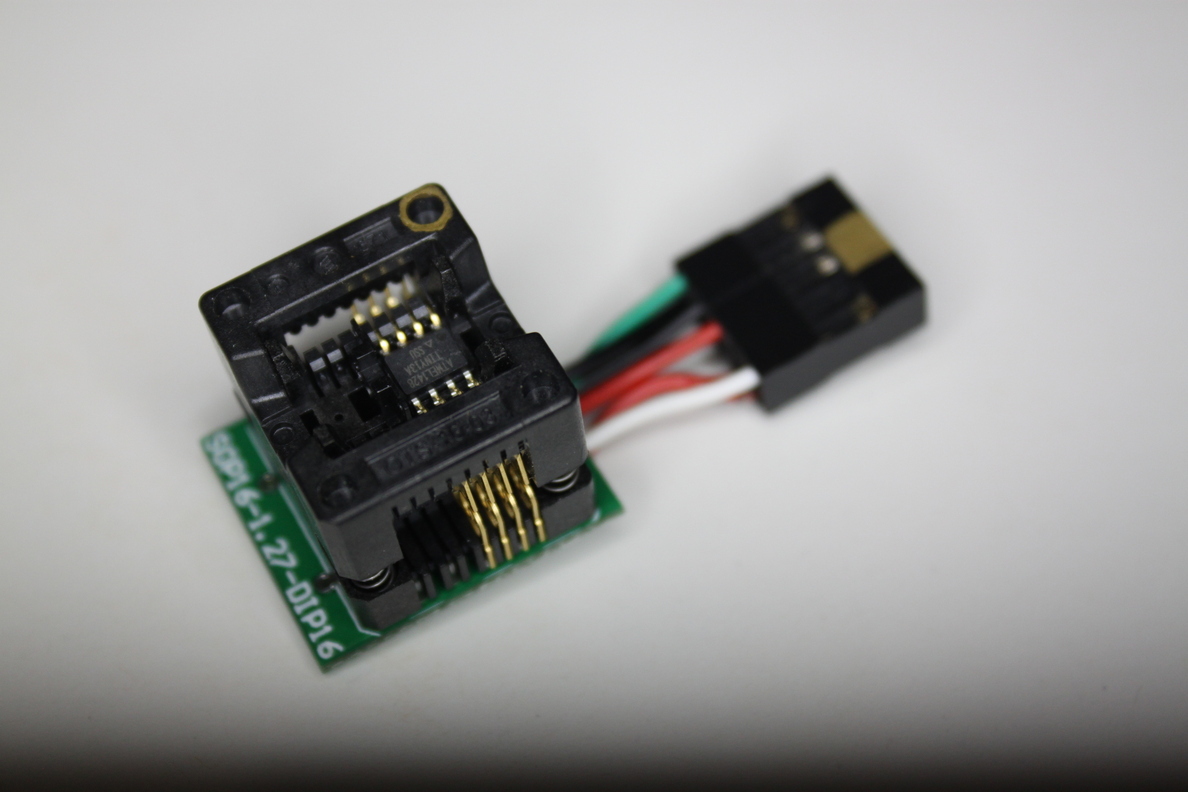
Что удалось сделать из колодок для тинек (оказалось — очень удобно).
Контрольный светодиод между выходами PB3-PB4.
Контрольный светодиод между выходами PB3-PB4.
References
Archive with modified firmware (source + compiled main.hex firmware): app.box.com/s/xz4neeubv663rvcem12pbctq91hutpp2
Original firmware (USBasp firmware from Thomas Fischl): www.fischl.de/usbasp
Hacking an AVR programmer: www.sciencetronics / greenphotons /? p = 938
An article on the hub on the same topic: "How to get a Chinese USB-programmer for $ 5 to work on Linux"