Overview of the Strela robotic platform or a simple do-it-yourself bluetooth bot
Recently, we received a gift for our workshop from one of the leading manufacturers of electronic training kits in Russia - from Amperka . The Strela board is a new development of the company and they suggested that we try to apply it in real conditions.
The main idea of the Strela platform is the rejection of the modular principle of building a robotic Arduino project. Instead of a set of shields, Amperka suggests using one universal board, which implements the functionality of many shields.

In the article, I offer you my opinion on what came out of it, and tell you how we built our robot, controlled by bluetooth from an Android smartphone. I tried to be as impartial as possible, but a certain amount of subjectivity, of course, is present.
I teach special disciplines at the College of Radio Engineering and in my free time I engage in project activities with students. This can not be called a circle in the usual sense of the word. I just have a group of young people who individually or in very small groups work on what they like. Someone is engaged in 3D printing, someone copters, someone programming, etc. That is, I have an idea about teaching people electronics in practice.
At the main place of work, I am professionally engaged in the development of electronics and have extensive experience working on real iron projects. I can express my impressions not only as a teacher, but also as an engineer.
When I was offered to try to use Strela in my work and share my experience, I, of course, immediately agreed. Everything that Amperka gave us, I fully handed over to one of my students, who became interested in the task, and here is what he did:
So, let's move on to the description of components.
The Strela platform is an Arduino-compatible board fully prepared for building robots. It was developed by Amperka and combines almost everything that might be needed to quickly build a robot. It is built on the basis of the Atmega32u4 controller and you need to work with it, as with the Arduino Leonardo. She came to us in such a box:
In general, Amperka is attentive to the packaging. All of their products are neatly packaged in specially designed boxes. They focus primarily on a rather young audience and, I think, the guys are pleased to receive their purchases in this form, rather than wrapped in a bubble wrap.

In the box, the board itself:
At first glance, I was surprised that there was nothing but a board in the box. Later, when I started working with the board, I returned to this idea more than once, but I could not come up with what else could be in it. Really a lot of things are already installed on the board, but getting bonus bonuses is always very nice.
The board itself from the front ...
... and on the reverse side:
Here are the main characteristics of the board:
Meals
Board Mounted Peripherals
Connectors for connecting external elements
I hope the reader will forgive me for a free retelling. All features can be found on the wiki .
Today, robotics most often use the modular principle. That is, they have to buy separately almost all of these functions, and then combine them together.
Our robot made on shields would look something like this:

Strela includes several devices that are usually bought separately - Arduino, a shield with a motor driver, a voltage converter and breadboard for prototyping. This is the main idea of the board and it has two sides.
On the one hand, if you try to buy all these functions in the form of separate shields, you will get much more expensive and larger in size. That is, if, for example, you plan to purchase equipment for the robotics class, then Strela becomes profitable even from an economic point of view.
On the other hand, if there is a specific project that was conceived on Arduino and all the components of the system are known in advance, then most likely it will be possible to get by with one or two shields and gain in both cost and size.
It seems to me that the use of the platform will be justified within the framework of the robotics circle. It will be possible to constantly rearrange it on different robots, quickly add functions, etc. In a video review from Amperka, they generally built a robot in which they realized almost all the functionality at the same time. Also, Strela may be of interest to people who are knowledgeable in programming, who needed relatively simple hardware in their project. Strela will fit perfectly as a telepresence robot team performer or help breathe new life into a broken RC model.
To summarize this part, I want to list the pros and cons of the board. So, here is what I consider the merits:
And here is what I personally did not like:
That's how much this board costs now. It's hard to say a lot or a little. It may well turn out that when building a robot from scratch it is cheaper than assembling it on shields. In my experience, the price is fair. That is how much electronics costs if you develop it in Russia, sell officially and organize large-scale technical support.
We were also presented with a convenient two-wheeled Turtle platform .

It is quite large and fits the Boom in terms of engine power and the number of batteries in the built-in battery holder. It already has mounts for popular sensors and sensors.
In addition to the controller and the wheel platform, we were presented with many more useful things:
To quickly test the capabilities of the system, we decided to build a robot controlled via bluetooth. As a basis, we took an example from the arrow wiki .
To do this, the Strela platform itself will be enough, as a controller, a communication module, a wheeled platform and a battery. We decided not to use the battery compartment. Instead, we connected an 11.1V, 3A / h LiPo battery. In addition, we also connected an indicator.
Here's what we got in the end:
As you can see, the whole assembly comes down to assembling the chassis , screwing and connecting the boards and connecting a dozen wires.
This completes the assembly and begins programming.
An attentive reader could notice that the number of “legs” that Strela controls is significantly larger than that of Arduino Leonardo. For one LCD only, eight are needed. All of this is implemented and works simultaneously through the use of port extenders controlled through I2C. It would be rather difficult for a beginner to use the capabilities of these expanders if it were not for the ready-made Strela library .
Electronics developers very often neglect packaging, documentation, and software. But this does not apply to Amperka. There are tons of ready-made examples for the Strela board and a great library. It has only a few functions for working with digital outputs, but without them it would be very difficult to make all possible peripherals work simultaneously. They are as simple as the standard Arduino features. Their use allows you not to go into the intricacies of using the I2C bus, otherwise it took much more time to start working with it. On Arrow, the designation of the conclusions is changed in relation to the Arduino, but there is no confusion in this.
If you plan to use the LCD display, then it is better to download a guaranteed working library from the arrow on the arrow. And there you will find examples of working with her.
To control from the phone, as in the example, we used the finished application Bluetooth RC car from the Play Market.
My student already had little experience programming microcontrollers in C and writing programs for operating systems. With the development of Strela he had no problems. Adding an indicator was his initiative, from which I concluded that he really liked it. He brought to the indicator the speed set in the application (or rather, the relative duty cycle of the PWM signal).
I will post its code in its original form, just to show that it is and that it was written by a person with little experience. You can look under the spoiler, but you will not find there the perfect code or anything new.
The code is almost entirely borrowed from ready-made examples.
Strela is a fairly convenient platform for use in various robotic projects. It seems to me that when training or in weekend projects, the routine work of rolling LUT boards or mounting them should be minimized. Otherwise, losing enthusiasm is very easy.
We had a lot of ideas for using Arrows. In the near future we want to print a new frame for him, install a line sensor and make a robot moving along the line, with the possibility of manual control via bluetooth. I am sure that at the competitions our team will look worthy. The guys have already started working on the robot:
Product page on Amperka
Wiki website
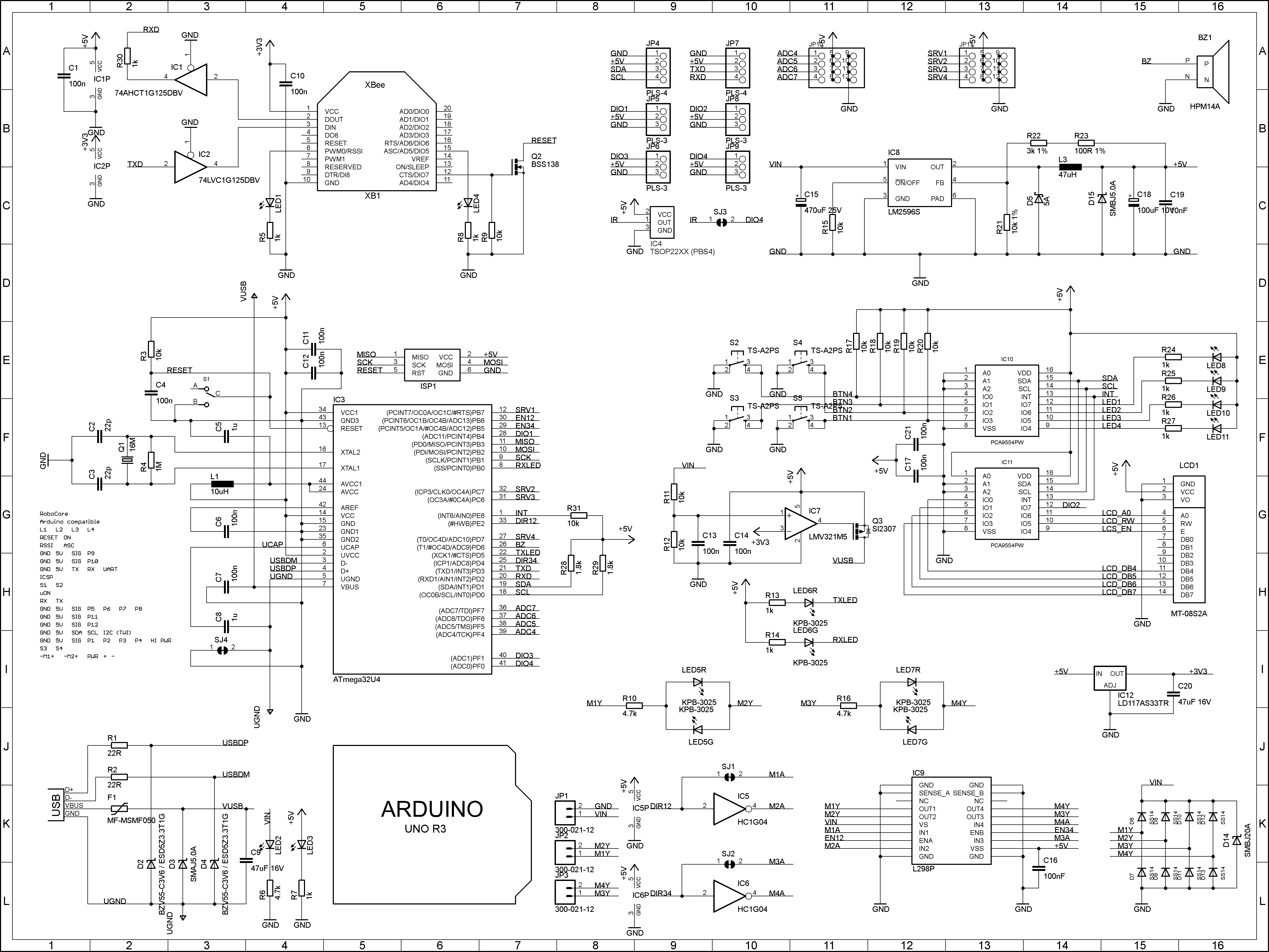
Schema
Library
Official review from Amperka
I myself like to program microcontrollers in C and I do my best to upgrade the Arduino-compatible hardware firmware with good software, so for advanced users I will add a description of the firmware for an arbitrary hex file to the Atmega32u4 memory using a bootloader. According to the engineer Amperka:
Option 1:
Option 2 - use ino .
The main idea of the Strela platform is the rejection of the modular principle of building a robotic Arduino project. Instead of a set of shields, Amperka suggests using one universal board, which implements the functionality of many shields.
In the article, I offer you my opinion on what came out of it, and tell you how we built our robot, controlled by bluetooth from an Android smartphone. I tried to be as impartial as possible, but a certain amount of subjectivity, of course, is present.
Background
I teach special disciplines at the College of Radio Engineering and in my free time I engage in project activities with students. This can not be called a circle in the usual sense of the word. I just have a group of young people who individually or in very small groups work on what they like. Someone is engaged in 3D printing, someone copters, someone programming, etc. That is, I have an idea about teaching people electronics in practice.
At the main place of work, I am professionally engaged in the development of electronics and have extensive experience working on real iron projects. I can express my impressions not only as a teacher, but also as an engineer.
When I was offered to try to use Strela in my work and share my experience, I, of course, immediately agreed. Everything that Amperka gave us, I fully handed over to one of my students, who became interested in the task, and here is what he did:
So, let's move on to the description of components.
Strela
The Strela platform is an Arduino-compatible board fully prepared for building robots. It was developed by Amperka and combines almost everything that might be needed to quickly build a robot. It is built on the basis of the Atmega32u4 controller and you need to work with it, as with the Arduino Leonardo. She came to us in such a box:
In general, Amperka is attentive to the packaging. All of their products are neatly packaged in specially designed boxes. They focus primarily on a rather young audience and, I think, the guys are pleased to receive their purchases in this form, rather than wrapped in a bubble wrap.
In the box, the board itself:
At first glance, I was surprised that there was nothing but a board in the box. Later, when I started working with the board, I returned to this idea more than once, but I could not come up with what else could be in it. Really a lot of things are already installed on the board, but getting bonus bonuses is always very nice.
The board itself from the front ...
... and on the reverse side:
Here are the main characteristics of the board:
Meals
- Input voltage: 7-24V. The motor driver is powered from the same voltage;
- Built-in switching stabilizer for 5V, 3A. The board itself consumes very little, that is, all of this can be used to power connected elements (sensors, servos, etc.);
- 3.3V linear stabilizer for powering communication modules;
- USB powered. On the Arrow, a comparator is installed, which, when the main power is turned off, automatically switches to USB power. The load capacity on the 5-volt channel will fall to 500 mA, and the power outputs to the motors will stop working.
Board Mounted Peripherals
- Engine Driver L298P;
- Piezo emitter without built-in generator. It can be used to play any melody.
- RESET switch. That is exactly the switch. It essentially serves as a circuit breaker. You can turn off the board if you put an external toggle switch on the power, or you can just "turn off" the microcontroller with the RESET switch;
- Four custom buttons without fixing;
- Four user LEDs;
- Ten indicator LEDs for engine status, power and transmission lines.
Connectors for connecting external elements
- Two terminal blocks for connecting two DC motors 2A each, or one powerful 4A, or one stepper motor;
- 12 standard three-pin PLS connectors (GND, 5V, SIG). A variety of sensors, servos, etc. can be connected to them. Eight of them can work as analog inputs and 4 as PWM outputs;
- Connector for installing communication modules. All the necessary bindings are already on the board - it remains only to install the necessary module of the XBee format;
- A socket for connecting an IR receiver for remote control via an optical channel;
- Connector for LCD displays;
- Interfaces TWI / I2C, SPI, UART.
I hope the reader will forgive me for a free retelling. All features can be found on the wiki .
Today, robotics most often use the modular principle. That is, they have to buy separately almost all of these functions, and then combine them together.
Our robot made on shields would look something like this:
Strela includes several devices that are usually bought separately - Arduino, a shield with a motor driver, a voltage converter and breadboard for prototyping. This is the main idea of the board and it has two sides.
On the one hand, if you try to buy all these functions in the form of separate shields, you will get much more expensive and larger in size. That is, if, for example, you plan to purchase equipment for the robotics class, then Strela becomes profitable even from an economic point of view.
On the other hand, if there is a specific project that was conceived on Arduino and all the components of the system are known in advance, then most likely it will be possible to get by with one or two shields and gain in both cost and size.
It seems to me that the use of the platform will be justified within the framework of the robotics circle. It will be possible to constantly rearrange it on different robots, quickly add functions, etc. In a video review from Amperka, they generally built a robot in which they realized almost all the functionality at the same time. Also, Strela may be of interest to people who are knowledgeable in programming, who needed relatively simple hardware in their project. Strela will fit perfectly as a telepresence robot team performer or help breathe new life into a broken RC model.
To summarize this part, I want to list the pros and cons of the board. So, here is what I consider the merits:
- Externally, one board looks better than a set of shields. At a minimum, it will stand out from other robots;
- Fewer connections will have to be done by surface mounting. Easier assembly, higher reliability;
- The mounting holes on the board repeat the location of the holes on the Arduino Uno and there are four additional holes;
- Detailed documentation with a huge number of examples (I will add the main links at the end of the article);
- Library for working with the board. We will talk about it later separately;
- Box.
And here is what I personally did not like:
- Very often, circuitry is made without a margin of safety. But is extreme reliability required in home robotics?
- I do not like the white mask. I understand that with it the boards look more interesting, but nothing is visible under it!
- The 5-volt part of the board is powered by one power source. I would make separate stabilizers for the digital and power parts;
- Still, the board is by my standards big - 100x80mm. Big and all;
- Strela is not compatible with shields for Arduino. There is no standard footprint for this;
- I already spoke about a complete set.
That's how much this board costs now. It's hard to say a lot or a little. It may well turn out that when building a robot from scratch it is cheaper than assembling it on shields. In my experience, the price is fair. That is how much electronics costs if you develop it in Russia, sell officially and organize large-scale technical support.
Chassis for the robot
We were also presented with a convenient two-wheeled Turtle platform .
It is quite large and fits the Boom in terms of engine power and the number of batteries in the built-in battery holder. It already has mounts for popular sensors and sensors.
Bluetooth module, sensors and indicator
In addition to the controller and the wheel platform, we were presented with many more useful things:
- The platform-compatible Bluetooth Bee module is very easy to use. It connects to the controller via UART, and operating systems see it as a COM port. Probably the easiest way to connect something to a PC / smartphone wirelessly;
- 8x2 text screen . It is very convenient if the robot can show some status messages, especially since this display also supports the Russian alphabet;
- Two analog line sensors for building a line-tracer. Included with them are the usual three-wire cables for connection;
- Infrared rangefinder 10-80cm with mount . It has a voltage at the output, the magnitude of which depends on the measured distance;
- Two infrared obstacle sensors . At its output, either zero or one, depending on the set threshold and the measured distance.
Bluetooth bot assembly
To quickly test the capabilities of the system, we decided to build a robot controlled via bluetooth. As a basis, we took an example from the arrow wiki .
To do this, the Strela platform itself will be enough, as a controller, a communication module, a wheeled platform and a battery. We decided not to use the battery compartment. Instead, we connected an 11.1V, 3A / h LiPo battery. In addition, we also connected an indicator.
Here's what we got in the end:
As you can see, the whole assembly comes down to assembling the chassis , screwing and connecting the boards and connecting a dozen wires.
This completes the assembly and begins programming.
Arrow Programming
An attentive reader could notice that the number of “legs” that Strela controls is significantly larger than that of Arduino Leonardo. For one LCD only, eight are needed. All of this is implemented and works simultaneously through the use of port extenders controlled through I2C. It would be rather difficult for a beginner to use the capabilities of these expanders if it were not for the ready-made Strela library .
Electronics developers very often neglect packaging, documentation, and software. But this does not apply to Amperka. There are tons of ready-made examples for the Strela board and a great library. It has only a few functions for working with digital outputs, but without them it would be very difficult to make all possible peripherals work simultaneously. They are as simple as the standard Arduino features. Their use allows you not to go into the intricacies of using the I2C bus, otherwise it took much more time to start working with it. On Arrow, the designation of the conclusions is changed in relation to the Arduino, but there is no confusion in this.
If you plan to use the LCD display, then it is better to download a guaranteed working library from the arrow on the arrow. And there you will find examples of working with her.
To control from the phone, as in the example, we used the finished application Bluetooth RC car from the Play Market.
My student already had little experience programming microcontrollers in C and writing programs for operating systems. With the development of Strela he had no problems. Adding an indicator was his initiative, from which I concluded that he really liked it. He brought to the indicator the speed set in the application (or rather, the relative duty cycle of the PWM signal).
I will post its code in its original form, just to show that it is and that it was written by a person with little experience. You can look under the spoiler, but you will not find there the perfect code or anything new.
Bluetooth bot program
#include  // Библиотека для работы с I2C
#include  // Библиотека для работы со Стрелой
#include
int velocity = 0;  //Здесь будет храниться значение скорости
int defaultSpeed = 100; // это число мы будем использовать в логике поворотов
int start = 1;
LiquidCrystal_I2C lcd(LC_ADDR, LCEN, LCRW, LCRS, LC4, LC5, LC6, LC7);
void setup()
{
  Serial1.begin(9600);     //Bluetooth Bee по умолчанию использует эту скорость
  //motorConnection(1, 0);   // Я неправильно прикрутил один мотор
  //поэтому, чтобы их не перекручивать
  //можно воспользоваться этой функцией.
  //Направление вращения мотора 1 будет изменено.
  uDigitalWrite(L2, HIGH);
  uDigitalWrite(L3, HIGH);
  drive(0, 0);
  lcd.begin(8, 2);
  lcd.home();
  lcd.print("Hello");
  delay(2000);
  lcd.setCursor(0, 1);
  lcd.print("Load");
  delay(1000);
  lcd.print(".");
  delay(1000);
  lcd.print(".");
  delay(1000);
  lcd.print(".");
  delay(1000);
  lcd.clear();
  lcd.home();
  lcd.print("Connect");
  lcd.home();
}
void loop()
{
  if (Serial1.available() > 0)    //Если появились новые команды
  {
    if (start==1)
    {
      lcd.print("Conected");
      delay(1000);
      lcd.clear();
      lcd.setCursor(0, 0);
      lcd.print("Speed");
      lcd.setCursor(0, 1);
      start = 0;
    }   //вызываем функцию управления
    control();
  }
  //Здесь можно написать ещё много своего кода
}
void control()  // функция управления
{
  char dataIn = Serial1.read();  //Считаем значение пришедшей команды
  if (dataIn == 'F')         //Если пришла команда "F"
    drive(velocity, velocity);   //едем вперёд
  else if (dataIn == 'B')    //или если пришла команда "B"
    drive(-velocity, -velocity); //едем назад
  else if (dataIn == 'R')    //или если пришла команда "L"
    drive(-velocity, velocity);  //поворачиваем налево на месте
  else if (dataIn == 'L')    //или если пришла команда "R"
    drive(velocity, -velocity);  //поворачиваем направо на месте
  else if (dataIn == 'G')    //или если пришла команда "I", едем вперёд и направо
    drive(defaultSpeed+velocity, defaultSpeed-velocity);
  else if (dataIn == 'H')    //или если пришла команда "J", едем назад и направо
    drive(-defaultSpeed-velocity, -defaultSpeed+velocity);
  else if (dataIn == 'I')   //или если пришла команда "I", едем вперёд и налево
    drive(defaultSpeed-velocity, defaultSpeed+velocity);
  else if (dataIn == 'J')   //или если пришла команда "H", едем назад и налево
    drive(-defaultSpeed+velocity, -defaultSpeed-velocity);
  else if (dataIn == 'S')   //или если пришла команда "S", стоим
    drive(0, 0);
  else if (dataIn == 'U')   //или если "U", зажигаем "передние фары"
  {
    uDigitalWrite(L2, HIGH);
    uDigitalWrite(L3, HIGH);
  }
  else if (dataIn == 'u')   //или если "u", гасим "передние фары"
  {
    uDigitalWrite(L2, LOW);
    uDigitalWrite(L3, LOW);
  }
  else if (dataIn == 'W')   //или если "W", зажигаем "задние фары"
  {
    uDigitalWrite(L1, HIGH);
    uDigitalWrite(L4, HIGH);
  }
  else if (dataIn == 'w')   ////или если "w", гасим "задние фары"
  {
    uDigitalWrite(L1, LOW);
    uDigitalWrite(L4, LOW);
  }
  // если к нам пришло значение от 0 до 9
  else if (((dataIn - '0') >= 0) && ((dataIn - '0') <= 9))
  {
    velocity = (dataIn - '0') * 25; //сохраняем новое значение скорости
    lcd.setCursor(0, 1);
    lcd.print("   ");
    lcd.setCursor(0, 1);
    lcd.print(velocity);
    lcd.setCursor(0, 1);
  }
  else if (dataIn == 'q') //если "q" - полный газ!
  {
    velocity = 255;
    lcd.print(velocity);
    lcd.setCursor(0, 1);
  }
}
The code is almost entirely borrowed from ready-made examples.
Summary
Strela is a fairly convenient platform for use in various robotic projects. It seems to me that when training or in weekend projects, the routine work of rolling LUT boards or mounting them should be minimized. Otherwise, losing enthusiasm is very easy.
We had a lot of ideas for using Arrows. In the near future we want to print a new frame for him, install a line sensor and make a robot moving along the line, with the possibility of manual control via bluetooth. I am sure that at the competitions our team will look worthy. The guys have already started working on the robot:
Sources of materials
Product page on Amperka
Wiki website
Schema
Library
Official review from Amperka
PS
I myself like to program microcontrollers in C and I do my best to upgrade the Arduino-compatible hardware firmware with good software, so for advanced users I will add a description of the firmware for an arbitrary hex file to the Atmega32u4 memory using a bootloader. According to the engineer Amperka:
Option 1:
- Open the terminal, write there: C: \ Program Files (x86) \ Arduino / hardware / tools / avr / bin / avrdude -CC: \ Program Files (x86) \ Arduino / hardware / tools / avr / etc / avrdude.conf - v -v -v -v -patmega32u4 -cavr109 -PCOM19 -b57600 -D -Uflash: w: C: \ Your_C_FIRMWA.hex: i, where C: \ Your_C_FIRMWA.hex is your firmware file, COM19 - instead of 19 - COM number Arrow ports in bootloader mode (different from normal);
- Reboot MK;
- Within 8 seconds, we have time to execute the command from point 1 on the computer (in other words, press Enter);
- We are waiting for it to load.
Option 2 - use ino .