Design and installation of antenna mast structures of the microwave range
Not so long ago, in the open spaces of Habr, one could often find posts dedicated to any design and installation work in a coherent topic. I have always been especially interested in working in the field for several reasons.
Firstly, many technical solutions in such conditions are born literally on the spot, providing food for the mind. Secondly, for me it is a close topic.
Recently, the number of such posts has been reduced, it seems to me. This was an impetus for me to write about the work of the office in which I work. One of our directions is the construction of antenna mast structures from composite materials. For a more detailed description of all, albeit small, but the know-how of our office, I will report on a business trip that took place at the end of December in the village of Golubitskaya, in the Temryuk radio center. Our task was to install a 30-meter biconical microwave antenna.
In the mast version, it looks like this. Conductors are shown in blue. In our case - 16 pieces.

The fundamental difference between this antenna for our company was that it was decided to use a new antenna assembly method. The mast itself, in the new version, consists of pipes made of fiberglass and sleeves connecting them.
About shells is worth telling separately. For them, it was decided to use the “prepreg” material . In short, these are carbon fibers (or glass) with layers of epoxy. As semi-finished products from the factory, they come in the form of a roll and bend and cut perfectly, like linoleum. Further, depending on the thickness of the fibers, setting the desired shape, you need to apply your own heat treatment cycle. After that, the material hardens "to break" is not inferior to steel.
To form the sleeves we need, we built a thermal “cabinet” where, with the thermal cycle we needed, the shaft with the desired prepreg thickness rotated. Building a cabinet and forming shells also took a lot of time, but that's another story.
This is what the cabinet itself looks like: The


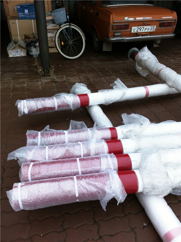
cartridges "reached" the object. The red shell is an acrylic film for UV protection.

Now I will proceed directly to the installation. Near the radio center there is an antenna field, where in advance for the antenna jacks for guy wires and warping itself have already been pre-tuned. The place of the future mast is marked in red.

Separately, it is worth noting the climatic features of the area. The radio center is located between the Black Sea and the estuary. From this, almost always the strongest ascending air flows, which affects the design of any high-rise structures there.
The first day we were engaged in the formation of the mast parts, glued sleeves to the nozzles. Separately, it is worth noting the top sleeve and the bottom, which were also "welded" on their own.
Top:
Bottom:

Since the work was carried out mostly in the field, the working day was limited to daylight hours, no powerful lighting was provided.
On the second day, parts of the antenna migrated to the field. And the antenna was assembled on the ground:
Next to the mast were attached braces from aramidrope, and conductors were attached to the conductive disks (see photo of the top and bottom).
Then the fun began - the rise of the antenna.
The lifting itself is carried out with the help of the lever, which we made of fiberglass pipe:

But the most difficult thing is to maintain the perpendicular plane of the antenna and the plane of the lever, otherwise, with strong tension, the mast shoulder can not stand and crack. This problem is solved by constant monitoring of guy rods tension during the whole ascent.
It was already pretty dark and it was impossible to work, I had to postpone the final rise the next day.
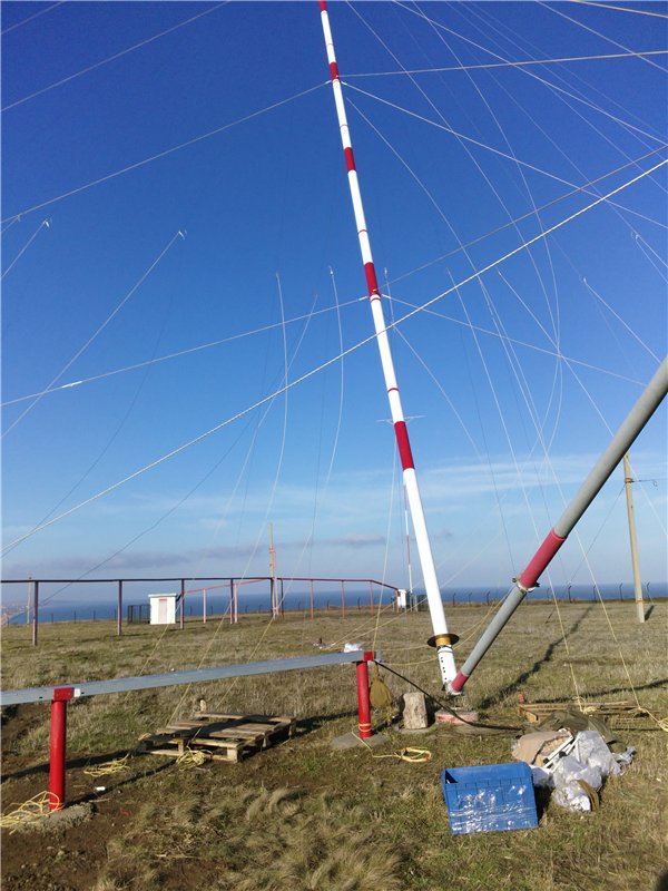
On such a sunny morning the next day we were met:

Immediately in the morning we began the gradual lifting of the mast. A few photos from this process:

After raising, it is important to set the vertical level and compensate for the rope tension. For this, theodalite helps us.
All the remaining time until dark we attach the conductors (we also need to monitor the tension) to the lower conductive disk, from which the cable will go to the radio center.
The fastening of the cable itself took place in complete darkness with small flashlights in hand, and there is no photograph either.
Further, small debugging work and ... the antenna worked. They measured the SWR, asked the operator of another center to give a test score.
Unfortunately, due to problems with the ground conductors on the field, the antenna showed not the best characteristics. The SWR at our frequency is about 3, and the acceptance score is 2 to 3 out of 5. But work will be done to correct this problem.
Thanks to everyone who read! I hope it was interesting.
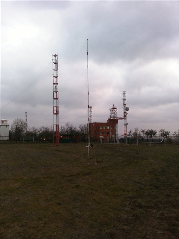
Ready, finished antenna:
Firstly, many technical solutions in such conditions are born literally on the spot, providing food for the mind. Secondly, for me it is a close topic.
Recently, the number of such posts has been reduced, it seems to me. This was an impetus for me to write about the work of the office in which I work. One of our directions is the construction of antenna mast structures from composite materials. For a more detailed description of all, albeit small, but the know-how of our office, I will report on a business trip that took place at the end of December in the village of Golubitskaya, in the Temryuk radio center. Our task was to install a 30-meter biconical microwave antenna.
In the mast version, it looks like this. Conductors are shown in blue. In our case - 16 pieces.
The fundamental difference between this antenna for our company was that it was decided to use a new antenna assembly method. The mast itself, in the new version, consists of pipes made of fiberglass and sleeves connecting them.
About shells is worth telling separately. For them, it was decided to use the “prepreg” material . In short, these are carbon fibers (or glass) with layers of epoxy. As semi-finished products from the factory, they come in the form of a roll and bend and cut perfectly, like linoleum. Further, depending on the thickness of the fibers, setting the desired shape, you need to apply your own heat treatment cycle. After that, the material hardens "to break" is not inferior to steel.
To form the sleeves we need, we built a thermal “cabinet” where, with the thermal cycle we needed, the shaft with the desired prepreg thickness rotated. Building a cabinet and forming shells also took a lot of time, but that's another story.
This is what the cabinet itself looks like: The
cartridges "reached" the object. The red shell is an acrylic film for UV protection.
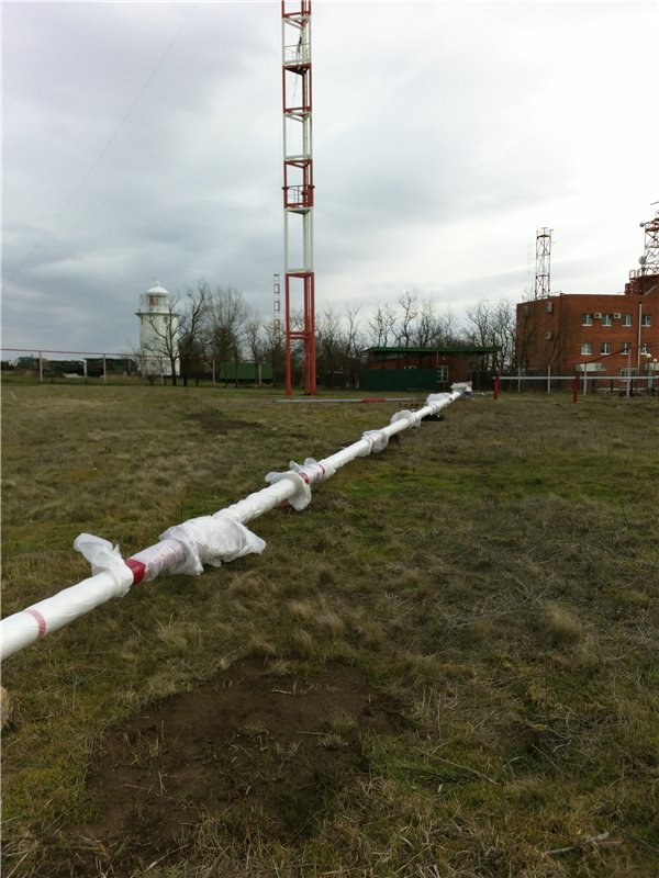
Now I will proceed directly to the installation. Near the radio center there is an antenna field, where in advance for the antenna jacks for guy wires and warping itself have already been pre-tuned. The place of the future mast is marked in red.
Separately, it is worth noting the climatic features of the area. The radio center is located between the Black Sea and the estuary. From this, almost always the strongest ascending air flows, which affects the design of any high-rise structures there.
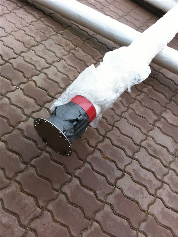
The first day we were engaged in the formation of the mast parts, glued sleeves to the nozzles. Separately, it is worth noting the top sleeve and the bottom, which were also "welded" on their own.
Top:
Bottom:
Since the work was carried out mostly in the field, the working day was limited to daylight hours, no powerful lighting was provided.
On the second day, parts of the antenna migrated to the field. And the antenna was assembled on the ground:
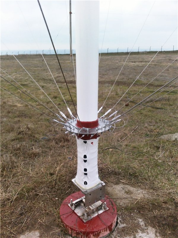
Next to the mast were attached braces from aramidrope, and conductors were attached to the conductive disks (see photo of the top and bottom).
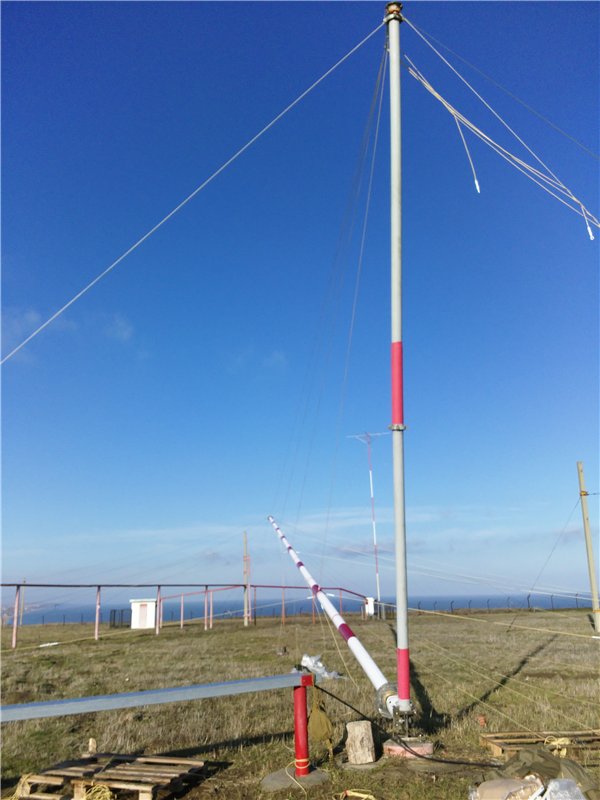
Then the fun began - the rise of the antenna.
The lifting itself is carried out with the help of the lever, which we made of fiberglass pipe:
But the most difficult thing is to maintain the perpendicular plane of the antenna and the plane of the lever, otherwise, with strong tension, the mast shoulder can not stand and crack. This problem is solved by constant monitoring of guy rods tension during the whole ascent.
It was already pretty dark and it was impossible to work, I had to postpone the final rise the next day.
On such a sunny morning the next day we were met:
Immediately in the morning we began the gradual lifting of the mast. A few photos from this process:
After raising, it is important to set the vertical level and compensate for the rope tension. For this, theodalite helps us.
All the remaining time until dark we attach the conductors (we also need to monitor the tension) to the lower conductive disk, from which the cable will go to the radio center.
The fastening of the cable itself took place in complete darkness with small flashlights in hand, and there is no photograph either.
Further, small debugging work and ... the antenna worked. They measured the SWR, asked the operator of another center to give a test score.
Unfortunately, due to problems with the ground conductors on the field, the antenna showed not the best characteristics. The SWR at our frequency is about 3, and the acceptance score is 2 to 3 out of 5. But work will be done to correct this problem.
Thanks to everyone who read! I hope it was interesting.
Ready, finished antenna: