Time-lapse camera on STM32L

According to Wikipedia, Time-lapse or slow motion filming is filming with a frequency lower than the standard shooting and projection frequency of 24 frames per second.
GIF time-lapse
Having started studying the STM32 microcontrollers and writing “HellowWorld” with a blinking LED, I realized that for a better understanding of the STM32, I need to implement something more complex using more microcontroller peripherals. So the idea of creating a Time-lapse camera.
The camera I developed will take photos about once every 5 seconds and save them to the SD card in jpeg format. Then they must be combined on a computer into a video file.
To create the camera, I used the following components:
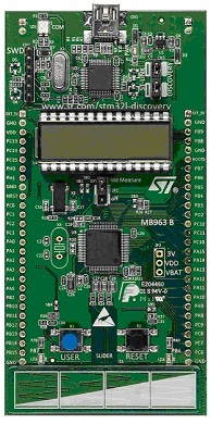
1) STM32L-DISCOVERY debug board . It has a microcontroller STM32L152RBT6 specially designed for the implementation of low-power devices, which would be useful for realizing the camera’s battery power.
2) ModuleLinkSprite JPEG Color Camera , operating on the UART interface. This module is a ready-made camera that outputs photos in JPEG format by UART. Configuration and management are also carried out on this interface.
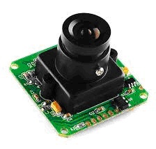
LinkSprite module specifications:
- Supported photo resolution: VGA / QVGA / 160 * 120;
- Speed from 9600 to 115200 (38400 by default);
- 5V power;
- Size 32mm X 32mm;
- Current consumption 80-100mA.
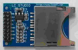
3) The module for connecting SD cards from LC STUDIO, the microcontroller will interact with it via the SPI interface.
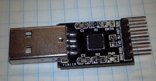
4) Any “usb to uart” adapter can also be useful for an initial study of the LinkSprite camera module (for this, the LS-Y201 program is required) and for outputting debugging information from the microcontroller to a computer. (I didn’t find beautiful photos of my adapter on the Internet, so I photographed it myself):
As they say, we will take the integral in parts:
First, we will understand how the LinkSprite camera works:
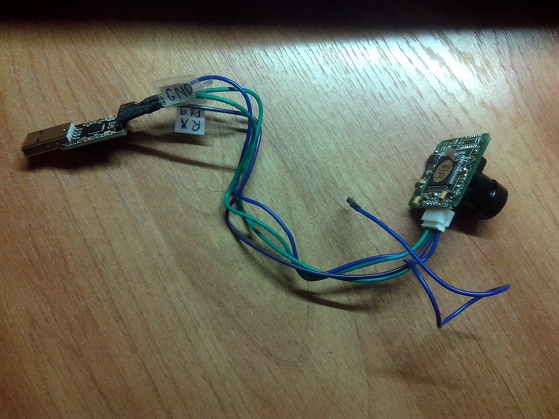
1) Assemble the circuit according to the figure (The camera module does not have a wire symbol , but there is a description in the LinkSprite manual , so if I couldn’t figure it out in my drawing, then refer to it).
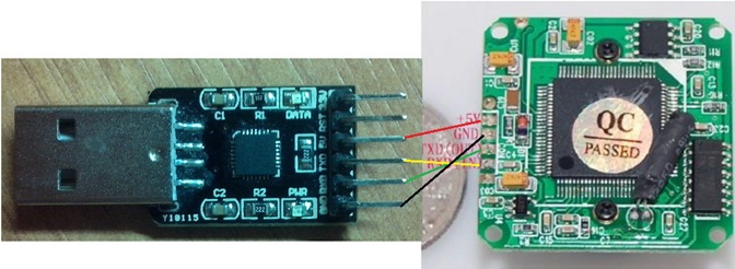
This design should work out (For myself, I marked all the wires coming from the camera module). One wire remains unconnected, if you believe the information on the site, then this is an analog video output.
2) Now we connect the adapter to the computer and run the LS-Y201 program . It is necessary to select the Com port of the adapter in it (The peculiarity is that you can only select from 1 to 4, so if the adapter will have a greater value, you will have to reconfigure it). Next, click the Open button . After that, the Com port will open and you can receive photos from the camera. To do this, use the Single Shot buttons (Take a single photo), Continues Shot (Take a photo until the Stop Shot button is pressed), Save Pictures (Saves the taken photo to the computer disk), Reset (Reset the camera to the initial settings), Exit (Exit the program).
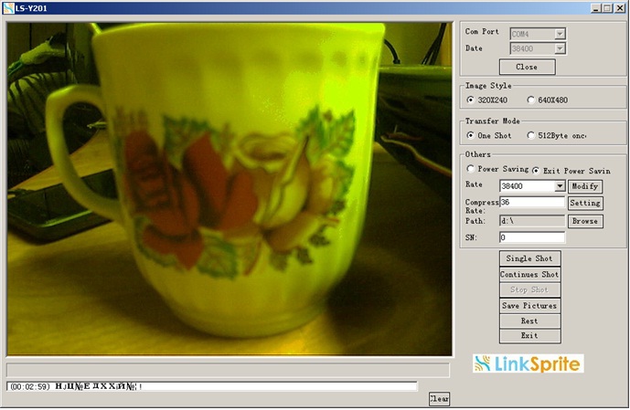
In the program settings, you can choose the resolution of the image 320x240 or 640x480 ( Image Style ), transfer mode of 512 bytes or the entire frame ( Transfer Mode ), transfer rate ( Rate , set from 9600 to 115200, and it will be necessary to change the speed of the Com port), photo compression ratio ( Compress Rate ), folder for saving photos ( Path ).
The exchange between the computer and the camera is carried out according to the protocol described in “LinkSprite JPEG Color Camera
Serial UART Interface ”.
The following commands exist:
- Reset - resets the camera to its initial settings;
- Take picture - instructs the camera to form a photo;
- Read JPEG file size - requests the size of the generated photo;
- Read JPEG file content - reads a photo from the camera;
- Stop takink pictures - sent to the camera after reading the photo:
- Compression Ratio - sets the compression ratio of the photo;
- Image size - sets the size of the photo;
- Power Saving - puts the camera in energy-saving mode (or displays from it);
- Changing Baud Rate - sets the exchange rate with the camera via UART.
The camera module is more or less understood, now we will assemble the STM32 camera.
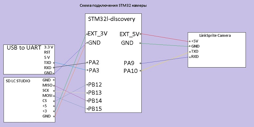
Such a design should be made from a pile of wires.
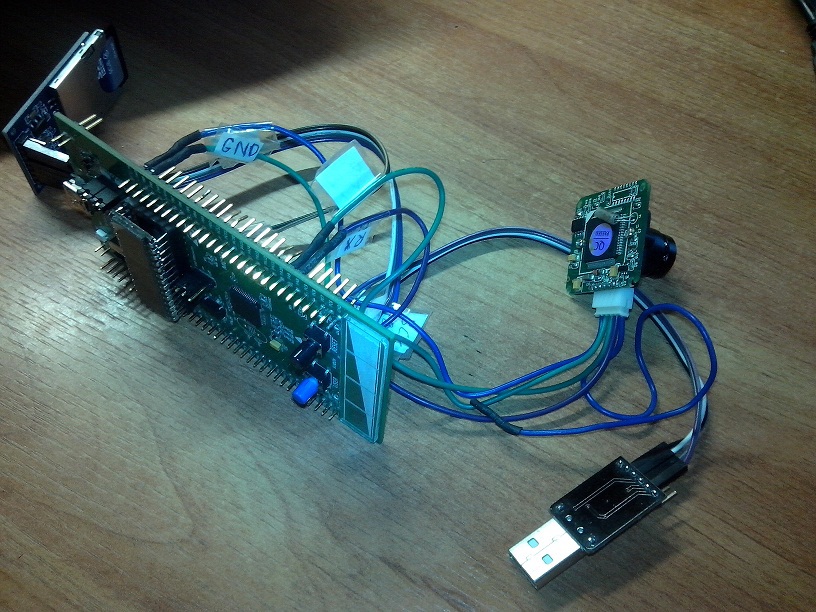
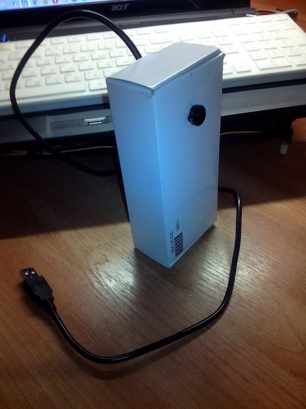
It’s enough for work, but you can cram everything into a building. I used a cardboard box from the battery.
Consider now the microcontroller program.
The microcontroller is tuned to a maximum frequency of 32 MHz from the integrated 16 MHz generator using PLL. To work with the camera module, UART1 is used. UART2 is used for output to the debug port (Interrupts and ring buffers are used to work on UART, for details on how to configure all this, see UART (USART) on STM32L (STM32) in this article ). SD card connected via SPI2. I also use an RTC timer to save photos based on time and date.
To work with peripherals, I used the STM32L1xx_StdPeriph library. Its description is in the StLib folder.
All the interaction functions of the microcontroller with the camera module, SD card and USB to UART adapter are described in MyLib.
To work with Fat, the FatFs library is used, its files are located in the fatfs folder.
The main.h file contains all the basic settings of the project, such as a description of the legs of the microcontroller used, a description of the parameters of the peripherals used.
I would like to focus on these lines:
#define DEBUG // Выводит отладочную информацию в UART2
#define ENABLE_POWER_SAVING // Переводит камеру в энергосберегающий режим
//#define JPEG_TO_UART    // Выводит кадр jpg в UART2
They can help with debugging and verifying camera health.
Consider the interaction algorithm of the microcontroller with the camera module.
The following functions are used to configure the camera module:
1. ResetCameraAtDifferentSpeeds () - initially, you must restart the camera module. To do this, a reset command is sent to him, since it is not known at what speed the camera was set before, we try to reset it to all available ones (from 19200 to 115200). In the case of a successful reset, the camera at bootup gives a sequence ending in “init end”. After that, it is necessary to maintain an interval of 2-3 seconds and you can continue to configure the camera.
2. Camera_ChBaudRate (4)- for faster frame transmission, you can increase the UART exchange rate or vice versa reduce it to eliminate transmission errors. By default, the camera is set to 38400. (4 is the speed of 115200)
3. Camera_ChPictureSize (2) - then the resolution of the photos generated by the camera is set. It can be 160x120, 320x240 or 640x480. (2- resolution 640x480)
4. Camera_ChCompression (0x36) - sets the compression ratio of photos (from 0x00 to 0xFF), the larger it is, the smaller the size they will have.
5. Camera_PowerSaving (1) - well, at the end, you can put the camera in energy-saving mode to reduce power consumption. (1- transfer to energy-saving mode)
All these actions are described in the init_JPEGCamera.h and init_JPEGCamera.c files located in the MyLib project folder.
After setting up the camera, you can get photos from it, for this you need to perform the following sequence:
1. Camera_PowerSaving (0) - if the camera was in energy-saving mode, remove it from this mode .. (0- exit from energy-saving mode)
2. Camera_TakePicture () - send a team to form a photo.
3. Camera_ReadData () - read the generated photo from the camera.
4. Camera_StopPictures () - send a command to complete the formation of the photo.
5. Camera_PowerSaving (1)- if necessary, put the camera in energy-saving mode.
The description of these functions is located in the functions_JPEGCamera.h and functions_JPEGCamera.c files located in the MyLib project folder.
Now consider the interaction algorithm with the SD card.
I use the FatFS library, according to this article Connecting an SD card via SPI to STM32F4xx and FatFS
Connecting a card is carried out using two functions:
1. Using the disk_initialize function , the card is initialized.
2. Next, you need to mount it f_mount .
After successfully completing these steps, you can perform various operations with the card, such as:
1. f_open - open a file,
2. f_close - closing the file;
3. f_mkdir - create a directory;
4. f_chdir - select a directory;
5. f_write - write to a file;
6. f_read - reading from a file.
I described the work with the camera and SD card, now we will consider the work of the program as a whole:
1. Initialize the SD card;
2. We initialize the camera module;
3. Open the file time.txt (the file must have one line in the format 01.01.2014_12: 00 ), which stores the time for counting the RTC timer;
4. Read the time and date from the file and configure RTC;
5. Close the file time.txt;
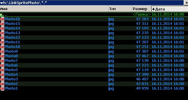
6. Create a directory for storing photos “LinkSpritePhoto”;
7. When you press the PA0 button on the board, we take a photo and save it to the card (As the photo is taken, the blue LED is on);
8. In case of failure to perform any of the functions, we fall into an endless loop and blink a green LED.
To start the camera in continuous mode, you need to uncomment the following lines in main.c:
//EnabledButtonStart = 101; // Для запуска в цикле раскомментировать эту строку
//Delay(300); // Задержка для запуска в цикле
And comment out this line:
EnabledButtonStart = 0; // Для запуска в цикле закомментировать эту строку
Then when you turn it on, the camera will start writing photos continuously.
In general, I made a description of how this camera works, now you can show the result of work.
GIF for those who do not play video
For some reason, all frames go yellow, possibly a lens without IR correction.
The camera sends UART information to the computer.

Saves frames to an SD card.
Well, the conclusion from everything that I have done:
- The STM32L1xx_StdPeriph library lowers the entry threshold for studying STM32l, but you still can’t do without studying the datasheet.
- In the future, I think to deal with the stm32l power modes so that the camera can be powered by battery.
List of links needed to repeat everything I did:
- Manual modulo LinkSprite JPEG Camera.
- LinkSprite JPEG Camera Module Description
- Connect SD card via SPI to STM32F4xx and FatFS
- UART (USART) on STM32L (STM32)
And also a link to download the STM32Camera.rar project