UDB. What is it? Part 5. Datapath. Useful stuff
- Transfer
We continue to consider UDB on the basis of Cypress’s proprietary documentation, namely useful trivia related to Datapath.
Previous articles in the cycle:
UDB. What is it? Part 1. Introduction. Pld.
UDB. What is it? Part 2. Datapath
UDB. What is it? Part 3. Datapath FIFO. .
UDB. What is it? Part 4. Datapath ALU
21.3.2.6 CRC / PRS Support
Datapath supports the generation of Control Cyclic Code (English Cyclic Redundancy Checking, CRC) and pseudo-random sequences (English Pseudo Random Sequence, PRS). Chained signals are traced between Datapath blocks to support CRC / PRS longer than 8 bits.
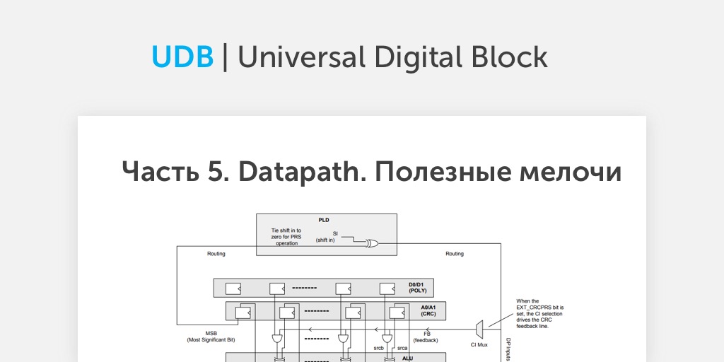
The most significant bit (MSB) of the older CRC / PRS block is selected and traced (and chained together with other blocks) to the lower blocks. After that, an XOR operation with input data (SI data) is applied to the MSB, providing a feedback signal (feedback, FB). After that, the feedback signal is traced (and chained together with other blocks) to the lower blocks. This feedback value is used on all blocks to perform an XOR operation.polynomial (with register Data0 or Data1) with the current value of the battery.
Figure 21-18 shows the structural configuration of a CRC operation. The PRS configuration is identical, but the input shift data (SI) is drawn to 0. In PRS mode, D0 or D1 contains the value of a polynomial, and A0 or A1 contains the initial value (seed) and the CRC value, which is obtained after the calculation.
Translator's note.
In all likelihood, this offer has a typo in the company documentation, since a random number should be obtained in the PRS mode. And information about the CRC is available just below.

Figure 21-18. The functional structure of the CRC.
To activate CRC support, you need to assign the value CFB_EN in the dynamic configuration RAM to value 1. This activates the AND operationin relation to the SRCB ALU input and the CRC feedback signal. If this bit is set to zero, the feedback signal is assigned to one, which allows normal arithmetic operations to be performed. Dynamic control of this bit on each cycle allows CRC / PRS operations to be interleaved with other arithmetic operations.
Linking CRC / PRS to chains
Figure 21-19 shows an example of CRC / PRS binding in chains between three UDBs. This script supports operation in modes with a bit width from 17 to 24 bits. Chaining control bits in chains are set according to the position of the Datapath in the chain (see figure).

Figure 21-19. CRC / PRS chaining configuration.
How to chain a CRC / PRS feedback signal (cfbo, cfbi):
- If the selected block is the youngest, the feedback signal on this block is generated from the built-in logic, which takes the right-shift input (sir) and performs an XOR operation with the most significant bit on them . (In the case of PRS, the “sir” signal is set to “0”).
- If the selected block is not a low block, the CHAIN FB configuration bit must be set, and feedback is transmitted along the chain from the previous block.
How to chain a CRC / PRS MSB signal (cmsbo, cmsbi):
- If the selected block is the highest, the MSB configuration bit (according to the selected polynomial) is configured using the MSB_SEL configuration bits .
- If the selected block is not the highest, the CHAIN MSB configuration bit must be set, and the MSB signal is transmitted along the chain from the next block.
CRC / PRS Polynomial Specification
As an example of a polynomial configuration for writing to the corresponding D0 / D1 register, consider the CCITT CRC-16 polynomial , which looks like x 16 + x 12 + x 5 + 1. The method of extracting the data format from the polynomial is shown in Figure 21-20. The term X0 is by definition always equal to 1, therefore, it does not need to be written down. For all other members of the polynomial, the unit is set to the required positions, as shown in the figure.

Figure 21-20. The format of the CCITT CRC16 polynomial.
Please note that the format of a polynomial is slightly different from the format specified in the classic hexadecimal format. For example, the CCITT CRC16 polynomial is usually denoted as 1021H. To convert it to the required format for Datapath, you need to shift right by one position and add 1 to the MSB bit. In this case, the correct value of the polynomial that needs to be written in D0 or in D1 is 8810H .
CRC / PRS Configuration Example
The following is a brief description of the CRC / PRS configuration requirements, provided that D0 is a polynomial and CRC / PRS is calculated in A0:
- Choose a suitable polynomial (example above), and write it in D0.
- Choose a suitable seed value (for example, all zeros for CRC or all units for PRS) and write it to A0.
- If necessary, set up chaining as described above.
- Select the MSB position as described above.
- Configure dynamic configuration RAM fields:
a. Select D0 as ALU “SRCB” (ALU B data source)
b. Select A0 as ALU “SRCA” (ALU A data source)
c. Select XOR for ALU operation
d. Select SHIFT LEFT for SHIFT operation
e. Select CFB_EN to enable CRC / PRS support
f. Select ALU as the recording source A0.
When you select CRC, you need to set the shift in right field for the input data and supply data for this input at each cycle. If you select PRS, you must assign shift in right to 0.
Such a UDB configuration generates the necessary CRC or generates the most significant bit that can be thrown out, removing the pseudo-random sequence from it.
External mode CRC / PRS
To enable support for external CRC or PRS calculations, you can set a static configuration bit ( EXT CRCPRS ). As shown in Figure 21-21, the CRC feedback calculation is performed in the PLD block. When the bit is cocked, the CRC feedback signal is transmitted directly from the input CI multiplexer (Carry In), bypassing the internal calculations. The figure shows a simple configuration that supports CRC or PRS up to 8-bit. Embedded electronic circuits are commonly used, but this parameter allows for more complex configurations, such as 16-bit CRC / PRS functions in a single UDB, using time division multiplexing.
Figure 21-21. External mode CRC / PRS.
In this mode, the CFB_EN bitDynamic configuration RAM also controls whether the AND operation to the CRC feedback signal at the CRCB ALU input is used or not. Thus, as in the case of the internal CRC / PRS mode, this function can alternate with other functions if necessary.
21.3.2.7 Datapath Outputs and Multiplexing
Conditions are generated from battery trigger values, ALU outputs, and FIFO status. These conditions can be transmitted via digital trace channels to other UDBs, to generate interrupt requests or to DMA, or to the “microchip legs”. The 16 possible conditions are shown in the table below.
Table 21-16. Datapath condition generation.
| Title | Condition | Chain? | Description |
|---|---|---|---|
| ce0 | Compare Equal | Yes | A0 == D0 |
| cl0 | Compare Less Than / Compare Less Than | Yes | A0 <D0 |
| z0 | Zero detected | Yes | A0 == 00h |
| ff0 | Units detected | Yes | A0 = FFh |
| ce1 | Compare Equal | Yes | A1 or A0 == D1 or A0 (dynamic selection) |
| cl1 | Compare Less Than / Compare Less Than | Yes | A1 or A0 <D1, or A0 (dynamic selection) |
| z1 | Zero detected | Yes | A1 == 00h |
| ff1 | Units detected | Yes | A1 == FFh |
| ov_msb | Overflow | Not | Carry (msb) ^ Carry (msb-1) |
| co_msb | Carry / Carry Out | Yes | Migration of a specific MSB bit |
| cmsb | CRC MSB | Yes | MSB CRC / PRS Functions |
| so | Shift Out | Yes | The data output of the selected shift operation |
| f0_blk_stat | FIFO0 block status | Not | Description depends on FIFO configuration. |
| f1_blk_stat | FIFO1 block status | Not | Description depends on FIFO configuration. |
| f0_bus_stat | FIFO0 bus status | Not | Description depends on FIFO configuration. |
| f1_bus_stat | FIFO1 bus status | Not | Description depends on FIFO configuration. |

Figure 21-22. Connections to the output multiplexer.
Comparisons
There are two comparisons, one of which has fixed sources ( Compare 0 ) and the other dynamically selectable ( Compare 1 ). Each comparison has an 8-bit static mask overlay register that allows the comparison to be performed in the specified bit field. By default, masking is disabled (all bits are compared) and must be activated manually.
Compare 1 inputs are configured dynamically. As shown in the table below, there are four Compare 1 parameters that apply to the “less” and “equal” conditions. The SELA CMP configuration bits and SELB CMP define possible comparison configurations. The dynamic configuration RAM bits define one of the configurations (A or B) on each cycle.
Table 21-17. Configuration comparisons.
| CMP SEL A CMP SEL B | Режим сравнения для Сompare 1 |
|---|---|
| 00 | А1 сравнивается с D1 |
| 01 | A1 сравнивается с A0 |
| 10 | A0 сравнивается с D1 |
| 11 | A0 сравнивается с А0 |

Figure 21-23. Linking in the chain of comparison "equal to".
Figure 21-24 shows the linking in the “less” comparison chain. In this case, the output (cl0) for this block is formed by the “less than” comparison circuit and is unconditional. This signal is combined by ORwith the incoming result from the chain, if the condition for the current block is "equal" and the linking mode is enabled in the chains.

Figure 21-24. Chaining comparison "less than"
Detection of all zeros and all ones
Each battery has a detector of all zeros and a detector of all units. These conditions can be statically chained as specified in the UDB configuration registers. The binding mode is specified in the UDB configuration registers. Linking to the zero-detection chain follows the same concept as the "equal" comparison. If chaining is activated, an AND operation is applied to the successfully linked data .
Overflow
Overflow is defined as XOR transfer operation to MSB and transfer from MSB. Calculations are performed on the current MSB, as specified in the MSB_SEL bits . This condition cannot be chained, however, the calculation will be correct if it is performed on the older Datapath function of the total bit length as long as the transfer between the blocks is connected.
21.3.2.8 Parallel Inputs and Outputs Datapath
As shown in Figure 21-25, Parallel In (PI) and Parallel Out (PO) signals provide limited opportunity for delivering data and tracing resources to Datapath and outputting data from it. PO signals are always available for tracing as a choice of the ALU asrc value between A0 and A1.
Translator's note.
This is an extremely important mechanism that allows UDB to work not only with serial, but also with parallel data. For some reason this is not underlined in this document, but this can be casually read in one of the Application Notes.

Figure 21-25. Parallel In / Out Datapath signals.
To enter data in the ALU, you must select Parallel In. There are two modes: static and dynamic. In static mode, the PI SEL bit causes the asrc ALU value to PI. The PI DYN bit is used to provide dynamic PI mode. When it is cocked and, provided that PI SEL is 0, the PI multiplexer can control the CFB_EN dynamic control bit . The main function of the CFB_EN bit is to provide PRS / CRC functionality.
21.3.2.9 Chaining Datapath
Each Datapath block has an 8-bit ALU, which is designed to chain-chain, translate, capture triggers and conditional signals to the nearest neighboring Datapath to create arithmetic functions and shift registers of greater bitness. These signals, connected in chains, are distinguished and allow you to effectively implement 16- 24-bit and 32-bit functions in one cycle without racing and other problems arising from delays in the trace channels. In addition, the chaining of the grippers supports atomic reading of the batteries in the associated blocks. As shown in Figure 21-21, all generated conditional signals and capture signals are connected in a chain that moves from the youngest to the oldest unit. A left shift is also performed from the youngest to the oldest. Shift to the right is performed from senior to junior.

Figure 21-26. Stream Datapath chains.
21.3.2.10 Dynamic Configuration RAM
Each Datapath contains a dynamic configuration 8-word RAM with 16 bits (see Figure 21-27). The purpose of such RAM is to control the bits of the Datapath configuration on each cycle, based on the selected clocking for this Datapath. RAM has synchronous read and write ports for loading configuration via the system bus.
To quickly output these 16-bit words to Datapath, an additional asynchronous port for reading is provided as control bits. Asynchronous address inputs are selected by multiplexers from the Datapath inputs, which can be taken from any possible signals, including chip legs, PLD outputs, control unit outputs, or any Datapath outputs.
The main task of the asynchronous read port is to ensure fast decoding of the Datapath control bits in one cycle.

Figure 21-27. RAM I / O configuration.
The fields of the dynamic configuration RAM word are shown in the following tables along with a description of the use of each field.
| Register | Address | 15 | 14 | 13 | 12 | eleven | ten | 9 | eight |
|---|---|---|---|---|---|---|---|---|---|
| CFGRAM | 61h-6Fh (odd) | FUNC [2: 0] | FUNC [2: 0] | FUNC [2: 0] | SRCA | SRCB [1: 0] | SRCB [1: 0] | SHIFT [1: 0] | SHIFT [1: 0] |
| Register | Address | 7 | 6 | five | four | 3 | 2 | one | 0 |
|---|---|---|---|---|---|---|---|---|---|
| CFGRAM | 60h-6Eh (even) | A0 WRSRC [1: 0] | A0 WRSRC [1: 0] | A1 WRSRC [1: 0] | A1 WRSRC [1: 0] | CFB EN | CI SEL | SI SEL | CMPSEL |
| Field | Bits | Parameter | Meanings |
|---|---|---|---|
| FUNC [2: 0] | 3 | ALU function | 000 PASS 001 INC SRCA 010 DEC SRCA 011 ADD 100 SUB 101 XOR 110 AND 111 OR |
| SRCA | one | ALU A Input Source | 0 A0 1 A1 |
| Srcb | 2 | ALU B Input Source | 00 D0 01 D1 10 A0 11 A1 |
| SHIFT [1: 0] | 2 | Shift function | 00 PASS 01 Left Shift 10 Right Shift 11 Nibble Swap |
| A0 WR SRC [1: 0] | 2 | Record source for A0 | 00 None 01 ALU 10 D0 11 F0 |
| A1 WR SRC [1: 0] | 2 | Record source for A1 | 00 None 01 ALU 10 D1 11 F1 |
| CFB EN | one | CRC Feedback Activator | 0 Enable 1 Disable |
| CI SEL | one | Choosing a configuration for transfer | 0 ConfigA 1 ConfigB a |
| SI SEL | one | The choice of configuration for the shift | 0 ConfigA 1 ConfigB a |
| CMP SEL | one | Choosing a configuration for comparison | 0 ConfigA 1 ConfigB a |
To be continued…