Everything you wanted to know about Ethernet frames, but were afraid to ask, and for good reason
The article turned out to be quite voluminous, the topics discussed were the Ethenet frame formats, L3 Payload size boundaries, the evolution of Ethernet header sizes, Jumbo Frame, Baby-Giant, and a lot of things that were touched in passing. Something you have already seen in the review literature on data transmission networks, but you definitely haven’t come across many, if you haven’t done much research.
Let's start by looking at the formats of Ethernet frame headers in the queue for their birth.
Formats Ehternet frames.
1) Ethernet II

Fig. one
Preamble - a sequence of bits, which, in fact, is not part of the ETH header defines the beginning of the Ethernet frame.
DA (Destination Address) - destination MAC address; it can be unicast, multicast, broadcast.
SA (Source Address) - MAC address of the sender. Always unicast.
E-TYPE (EtherType) - Identifies the L3 protocol (for example, 0x0800 - Ipv4, 0x86DD - IPv6, 0x8100- indicates that the frame is tagged with 802.1q, etc. A list of all EtherType is standards.ieee.org/develop/regauth/ ethertype / eth.txt )
Payload - L3 packet size from 46 to 1500 bytes
FCS (Frame Check Sequences)- 4 byte CRC value used to detect transmission errors. It is calculated by the sender and placed in the FCS field. The receiving side calculates this value on its own and compares it with the received one.
This format was created in collaboration with 3 companies - DEC, Intel and Xerox. In this regard, the standard is also called the DIX Ethernet standard . This version of the standard was published in 1982 (the first version, Ehernet I - in 1980. The differences in versions are small, the format as a whole has remained unchanged). In 1997 This year the IEEE standard was added to the 802.3 standard, and at the moment, the vast majority of packets in Ethernet networks are encapsulated according to this standard.
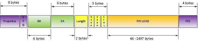
Fig. 2
As you understand, the IEEE committee could not watch calmly as power, money and women literally slip out of their hands. Therefore, busy with more pressing problems, it took some time to standardize Ethernet technology (in 1980 they got down to business, in 1983 they gave the world a draft, and in 1985 the standard itself), but with great enthusiasm. Having proclaimed innovation and optimization as its main principles, the committee issued the following frame format, which you can see in Figure 2.
First of all, we draw attention to the fact that the “unnecessary” E-TYPE field is converted to the Length field, which indicates the number of bytes next to it by and to the FCS field. Now, one could understand who was longer at the second level of the OSI system. Life has become better. Life has become more fun.
But, a pointer to the type of protocol of the 3rd level was needed, and IEEE gave the world the following innovation - two fields of 1 byte each - Source Service Access Point ( SSAP ) and Destination Service Access Point ( DSAP ). The goal, the same one, is to identify the superior protocol, but what an implementation! Now, due to the presence of two fields within the same session, a packet could be transmitted between different protocols, or the same protocol could be called differently at the two ends of the same session. BUT? What? Where is your Skolkovo?
Note: In life, this is of little use and SSAP / DSAP values usually coincide. For example, SAP for IP - 6, for STP - 42 (a full list of values is standards.ieee.org/develop/regauth/llc/public.html )
Without giving themselves a break, IEEE reserved 1 bit in SSAP and DSAP. In SSAP under the command or response packet, in DSAP under the group or individual address (see. Fig. 6). In Ethernet networks, these things did not receive distribution, but the number of bits in the SAP fields was reduced to 7, which left only 128 possible numbers for indicating the higher protocol. We remember this fact, we will come back to it.
It was already difficult to stop in our quest to make the best frame format on earth, and in the IEEE frame format 1 byte Control field appears . Responsible, not a lot, not a little, for Connection-less or Connection-oriented connection!
After exhaling and examining your brainchild, IEEE decided to take a break.
Comment: The 3 fields in question are DSAP, SNAP, and Control, and are the LLC header.
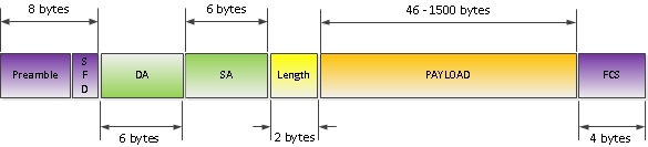
Fig. 3
This “substandard” was revealed in the world of Novell. It was the dashing 80s, everyone survived as best they could, and Novell was no exception. Having acquired the specification of the standard 802.3 / 802.2 in the process of development and having thrown the LLC header with a flick of the wrist, Novell got a pretty good frame format (with the ability to measure length at the second level!), But one significant drawback is the lack of the ability to specify a higher protocol. But, as you might already have guessed, the guys there were not stupid, and by common sense they worked out a solution - “let us turn our shortcomings to our own merits”, and limited this frame format exclusively to the IPX protocol, which we ourselves supported. And the idea is good, and the plan was strategically correct, but, as history has shown, not fortanulo.
As time went. The IEEE committee was aware that protocol numbers and money were running out. Grateful users filled the editorial office with letters, where the 3-byte LLC header was placed on a par with such great innovations of mankind as equipping a dog with the 5th foot, or with a sleeve that can be used to optimize female anatomy. It was impossible to wait further, it was time to reaffirm the world.

Fig. four
And to help those who are suffering from a lack of protocol numbers (there could be a total of 128 — we mentioned), IEEE introduces a new Ethernet SNAP frame standard (Figure 4). The main innovation is the addition of a 5-byte Subnetwork Access Protocol (SNAP) field, which in turn consists of two parts - a 3-byte Organizationally Unique Identifier (OUI) field and a 2-byte Protocol ID (PID) - Fig. 5.

Fig. 5
OUI or vendor code - allows you to identify proprietary protocols by indicating the vendor. For example, if you catch PVST + packet with WireShark, then in the OUI field you will see the code 0x00000c, which is the identifier of Cisco Systems (Fig. 6).
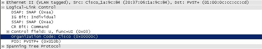
Fig. 6
Note:It is quite easy to meet the encapsulated packet in the format of the 802.3 SNAP frame now - these are all the protocols of the STP family, the protocols CDP, VTP, DTP.
The PID field is essentially the same EtherType field from DIX Ethernet II - 2 bytes for the indication of a higher level protocol. Since previously, for this, the DSAP and SSAP fields of the LLC header were used, to indicate that the type of the higher protocol should be looked at in the SNAP field, the DSAP and SSAP fields take a fixed value of 0xAA (also seen in Fig. 6)
Note: When used for Transfer of IP packets of LLC / SNAP frame format, IP MTU is reduced from 1500 to 1497 and 1492 bytes, respectively.
According to the headings in the frame format, in principle, everything. I would like to draw attention to another point in the frame format - the payload size. Where did this range come from - from 46 to 1500 bytes?
Probably everyone who at least read the first CCNA curriculum knows where the lower limit came from. This restriction is a consequence of the frame size limit of 64 bytes (64 bytes - 14 bytes L2 header - 4 bytes FCS = 46 bytes) superimposed by the CSMA / CD method - the time required to transmit 64 bytes by the network interface is necessary and sufficient to determine the collision in the environment Ethernet
Note: In modern networks where collisions are excluded, this restriction is no longer relevant, but the requirement remains. This is not the only “appendix” left over from that time, but we will talk about them in another article.
But where did these notorious 1500 bytes come from, the question is more complicated. I found the following explanation - there were several prerequisites for introducing an upper frame size limit:
In total, in the 802.3 standard, the frame size was limited to 1518 bytes from above, and payload by 1500 bytes (hence the default MTU size for the Ethernet interface).
Note: Frames of less than 64 bytes are called Runts, frames of more than 1518 bytes are called Giants. You can view the number of such frames received on the interface with the command
With the development of technology and specifications, the IEEE 802 line has undergone changes and frame size. The main further frame resizing (not MTU!):
All these oversized frames are grouped under the same name - Baby-Giant frames. The tacit upper size limit for Baby-Giant is 1600 bytes. Modern network interfaces will forward these frames, often even without changing the value of the HW MTU.
Separately, we pay attention to the 802.3AS specification - it increases the maximum frame size to 2000 (but keeps the MTU size at 1500 bytes!). The increase falls on the title and trailer. Initially, the increase was planned at 128 bytes - for native support by the 802.3 standard of the above extensions, but eventually converged on 2 thousand, apparently so as not to be collected twice (or as IEEE says - this frame size will support encapsulation requirements of the foreseeable future). The standard was approved in 2006, but apart from IEEE presentations, I have not met it. If anyone has something to add here (and not only here) - welcome to comment. In general, the tendency to increase the frame size while maintaining the PAYLOAD size gives rise to vague doubts in my head about the correctness of the chosen direction of movement.
Note: The FCoE frame settled a little aside from the above - the frame size is up to 2500 bytes, often these frames are called mini-jumbo. For their support, you must enable jumbo-frame support.
And the last Ethernet bastard is the Jumbo Frame (although if you translate Jumbo, it’s more likely that Hodor is looming - a reference to Game of Thrones). All frames exceeding the standard size of 1518 bytes fall under this description, with the exception of those discussed above. Jumbo packages are not reflected in the specifications of 802.3 and therefore the implementation remains on the conscience of each particular vendor. However, Jumbo frames exist as long as Ethernet exists. It is defined as follows:
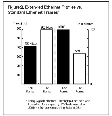
Fig. 7
This coin has a downside:

Fig. 8
In sum, the pros and cons of using Jumbo frames give us an unequivocal indication of where we can use this frame size. And so, in which applications in the data center can we use the Jumbo Frame for the benefit of all? There is a list like this (add-ons are welcome):
Note: Jumbo MTU also has an upper size limit. It is determined by the size of the FCS field (4 bytes) and the Cyclic Redundancy Check algorithm and is 11 455 bytes. In practice, the Jumbo MTU is usually limited to 9216 bytes, on some platforms 9000 bytes, on older hardware 8092 bytes (talk about Cisco).
Fuh, basically everything. What I wanted to consider in theory, considered. According to the configuration of MTU sizes and the theory with feints behind these three letters, I ask in my last article - “Maximum Transmission Unit (MTU). Myths and reefs. "
In conclusion, the promised link to the Alteon Networks report “Extended Frame Sizes for Next Generation Ethernets” - staff.psc.edu/mathis/MTU/AlteonExtendedFrames_W0601.pdf, and a small announcement for the next article - in it we will fall even lower - to the physical level, and we will deal with the heavy legacy of CSMA / CD, encoding, and, walking around, we’ll catch something else from the topical.
Let's start by looking at the formats of Ethernet frame headers in the queue for their birth.
Formats Ehternet frames.
1) Ethernet II
Fig. one
Preamble - a sequence of bits, which, in fact, is not part of the ETH header defines the beginning of the Ethernet frame.
DA (Destination Address) - destination MAC address; it can be unicast, multicast, broadcast.
SA (Source Address) - MAC address of the sender. Always unicast.
E-TYPE (EtherType) - Identifies the L3 protocol (for example, 0x0800 - Ipv4, 0x86DD - IPv6, 0x8100- indicates that the frame is tagged with 802.1q, etc. A list of all EtherType is standards.ieee.org/develop/regauth/ ethertype / eth.txt )
Payload - L3 packet size from 46 to 1500 bytes
FCS (Frame Check Sequences)- 4 byte CRC value used to detect transmission errors. It is calculated by the sender and placed in the FCS field. The receiving side calculates this value on its own and compares it with the received one.
This format was created in collaboration with 3 companies - DEC, Intel and Xerox. In this regard, the standard is also called the DIX Ethernet standard . This version of the standard was published in 1982 (the first version, Ehernet I - in 1980. The differences in versions are small, the format as a whole has remained unchanged). In 1997 This year the IEEE standard was added to the 802.3 standard, and at the moment, the vast majority of packets in Ethernet networks are encapsulated according to this standard.
2) Ethernet_802.3 / 802.2 (802.3 with LLC header)
Fig. 2
As you understand, the IEEE committee could not watch calmly as power, money and women literally slip out of their hands. Therefore, busy with more pressing problems, it took some time to standardize Ethernet technology (in 1980 they got down to business, in 1983 they gave the world a draft, and in 1985 the standard itself), but with great enthusiasm. Having proclaimed innovation and optimization as its main principles, the committee issued the following frame format, which you can see in Figure 2.
First of all, we draw attention to the fact that the “unnecessary” E-TYPE field is converted to the Length field, which indicates the number of bytes next to it by and to the FCS field. Now, one could understand who was longer at the second level of the OSI system. Life has become better. Life has become more fun.
But, a pointer to the type of protocol of the 3rd level was needed, and IEEE gave the world the following innovation - two fields of 1 byte each - Source Service Access Point ( SSAP ) and Destination Service Access Point ( DSAP ). The goal, the same one, is to identify the superior protocol, but what an implementation! Now, due to the presence of two fields within the same session, a packet could be transmitted between different protocols, or the same protocol could be called differently at the two ends of the same session. BUT? What? Where is your Skolkovo?
Note: In life, this is of little use and SSAP / DSAP values usually coincide. For example, SAP for IP - 6, for STP - 42 (a full list of values is standards.ieee.org/develop/regauth/llc/public.html )
Without giving themselves a break, IEEE reserved 1 bit in SSAP and DSAP. In SSAP under the command or response packet, in DSAP under the group or individual address (see. Fig. 6). In Ethernet networks, these things did not receive distribution, but the number of bits in the SAP fields was reduced to 7, which left only 128 possible numbers for indicating the higher protocol. We remember this fact, we will come back to it.
It was already difficult to stop in our quest to make the best frame format on earth, and in the IEEE frame format 1 byte Control field appears . Responsible, not a lot, not a little, for Connection-less or Connection-oriented connection!
After exhaling and examining your brainchild, IEEE decided to take a break.
Comment: The 3 fields in question are DSAP, SNAP, and Control, and are the LLC header.
3) "Raw" 802.3
Fig. 3
This “substandard” was revealed in the world of Novell. It was the dashing 80s, everyone survived as best they could, and Novell was no exception. Having acquired the specification of the standard 802.3 / 802.2 in the process of development and having thrown the LLC header with a flick of the wrist, Novell got a pretty good frame format (with the ability to measure length at the second level!), But one significant drawback is the lack of the ability to specify a higher protocol. But, as you might already have guessed, the guys there were not stupid, and by common sense they worked out a solution - “let us turn our shortcomings to our own merits”, and limited this frame format exclusively to the IPX protocol, which we ourselves supported. And the idea is good, and the plan was strategically correct, but, as history has shown, not fortanulo.
4) 802.3 with SNAP Header.
As time went. The IEEE committee was aware that protocol numbers and money were running out. Grateful users filled the editorial office with letters, where the 3-byte LLC header was placed on a par with such great innovations of mankind as equipping a dog with the 5th foot, or with a sleeve that can be used to optimize female anatomy. It was impossible to wait further, it was time to reaffirm the world.
Fig. four
And to help those who are suffering from a lack of protocol numbers (there could be a total of 128 — we mentioned), IEEE introduces a new Ethernet SNAP frame standard (Figure 4). The main innovation is the addition of a 5-byte Subnetwork Access Protocol (SNAP) field, which in turn consists of two parts - a 3-byte Organizationally Unique Identifier (OUI) field and a 2-byte Protocol ID (PID) - Fig. 5.
Fig. 5
OUI or vendor code - allows you to identify proprietary protocols by indicating the vendor. For example, if you catch PVST + packet with WireShark, then in the OUI field you will see the code 0x00000c, which is the identifier of Cisco Systems (Fig. 6).
Fig. 6
Note:It is quite easy to meet the encapsulated packet in the format of the 802.3 SNAP frame now - these are all the protocols of the STP family, the protocols CDP, VTP, DTP.
The PID field is essentially the same EtherType field from DIX Ethernet II - 2 bytes for the indication of a higher level protocol. Since previously, for this, the DSAP and SSAP fields of the LLC header were used, to indicate that the type of the higher protocol should be looked at in the SNAP field, the DSAP and SSAP fields take a fixed value of 0xAA (also seen in Fig. 6)
Note: When used for Transfer of IP packets of LLC / SNAP frame format, IP MTU is reduced from 1500 to 1497 and 1492 bytes, respectively.
According to the headings in the frame format, in principle, everything. I would like to draw attention to another point in the frame format - the payload size. Where did this range come from - from 46 to 1500 bytes?
Size L3 Payload.
Probably everyone who at least read the first CCNA curriculum knows where the lower limit came from. This restriction is a consequence of the frame size limit of 64 bytes (64 bytes - 14 bytes L2 header - 4 bytes FCS = 46 bytes) superimposed by the CSMA / CD method - the time required to transmit 64 bytes by the network interface is necessary and sufficient to determine the collision in the environment Ethernet
Note: In modern networks where collisions are excluded, this restriction is no longer relevant, but the requirement remains. This is not the only “appendix” left over from that time, but we will talk about them in another article.
But where did these notorious 1500 bytes come from, the question is more complicated. I found the following explanation - there were several prerequisites for introducing an upper frame size limit:
- Transmission Delay - The larger the frame, the longer the transmission. For early networks, where the Collision domain was not limited to a port, and all stations had to wait for the transfer to complete, this was a serious problem.
- The larger the frame, the greater the likelihood that the frame will be damaged during transmission, which will lead to the need for retransmission, and all devices in the collision domain will be forced to wait again.
- Limitations imposed by the memory of buffers used for the interface - at that time (1979), the increase in buffers significantly increased the cost of the interface.
- The restriction introduced by the Length / Type field is stipulated in the standard that all values above 1536 (from 05-DD to 05-FF.) Indicate EtherType, respectively, the length should be less than 05-DC. (I really have a suspicion that this is more a consequence than a premise, but it seems like info from the developers of the standard 802.3)
In total, in the 802.3 standard, the frame size was limited to 1518 bytes from above, and payload by 1500 bytes (hence the default MTU size for the Ethernet interface).
Note: Frames of less than 64 bytes are called Runts, frames of more than 1518 bytes are called Giants. You can view the number of such frames received on the interface with the command
show interface gigabitEthernet module/number andshow interface gigabitEthernet module/number counters errors.Moreover, before IOS 12.1 (19), both frames with the wrong and the correct CRS went to the counters (although the latter did not always drop - it depends on the platform and conditions). But starting from 12.1. (19) only those runt and giant frames are displayed in these counters that have the wrong CRS, frames less than 64 bytes, but with the correct CRS (the reason for the occurrence is usually related to 802.1Q detection or the frame source, and not problems physical level) from this version fall into the Undersize counter, they drop, or forward forward, depends on the platform.The evolution of Ethernet header sizes.
With the development of technology and specifications, the IEEE 802 line has undergone changes and frame size. The main further frame resizing (not MTU!):
- 802.3AC - increases the maximum frame size to 1522 - adds a Q-tag - carrying information about 802.1Q (VLAN tag) and 802.1p (bits for COS)
- 802.1AD - increases the maximum frame size to 1526, QinQ support
- 802.1AH (MIM) - Provider Bridge Backbone Mac in Mac + 30 bytes to frame size
- MPLS - increase the frame size on the label stack 1518 + n * 4, where n is the number of labels on the stack.
- 802.1AE - Mac Security, the Security Tag and Message Authentication Code fields + 68 bytes to the frame size are added to the standard fields.
All these oversized frames are grouped under the same name - Baby-Giant frames. The tacit upper size limit for Baby-Giant is 1600 bytes. Modern network interfaces will forward these frames, often even without changing the value of the HW MTU.
Separately, we pay attention to the 802.3AS specification - it increases the maximum frame size to 2000 (but keeps the MTU size at 1500 bytes!). The increase falls on the title and trailer. Initially, the increase was planned at 128 bytes - for native support by the 802.3 standard of the above extensions, but eventually converged on 2 thousand, apparently so as not to be collected twice (or as IEEE says - this frame size will support encapsulation requirements of the foreseeable future). The standard was approved in 2006, but apart from IEEE presentations, I have not met it. If anyone has something to add here (and not only here) - welcome to comment. In general, the tendency to increase the frame size while maintaining the PAYLOAD size gives rise to vague doubts in my head about the correctness of the chosen direction of movement.
Note: The FCoE frame settled a little aside from the above - the frame size is up to 2500 bytes, often these frames are called mini-jumbo. For their support, you must enable jumbo-frame support.
And the last Ethernet bastard is the Jumbo Frame (although if you translate Jumbo, it’s more likely that Hodor is looming - a reference to Game of Thrones). All frames exceeding the standard size of 1518 bytes fall under this description, with the exception of those discussed above. Jumbo packages are not reflected in the specifications of 802.3 and therefore the implementation remains on the conscience of each particular vendor. However, Jumbo frames exist as long as Ethernet exists. It is defined as follows:
- Benefit of payload to heading ratio. The greater this ratio, the more efficient we can use communication lines. Of course, the gap here will not be the same as in comparison with the use of packets of 64 bytes and 1518 bytes for TCP sessions. But you can win your own 3-8 percent, depending on the type of traffic.
- A significantly smaller number of headers generates less load on the Forwading Engine, as well as on the service Engine. For example, the frame rate for a 10G link loaded with 1500 byte frames is 812 744 frames per second, and the same link loaded with Jumbo frames of 9000 bytes generates a frame rate of only 138 587 frames per second. Figure 7 shows a graph from the Alteon Networks report (link will be at the bottom of the article) CPU utilization and gigabit link, depending on the type of frame size used.
- Increase TCP Throughput when resizing MTUs - staff.psc.edu/rreddy/networking/mtu.html
Fig. 7
This coin has a downside:
- The larger the frame, the longer it will be transmitted (Fig. 8):
- Buffers in the memory of network devices fill up faster, which can cause unwanted consequences. In fact, it can be solved at the stage of equipment design, but it increases the cost.
- A proprietary implementation for each manufacturer - all devices must support either the same Jumbo frame sizes, or sets of sizes.
- The use of large network areas under different administrative control, in fact, is impossible, due to the lack of a Jumbo Frame Discovery mechanism - the intermediate node may not support Jumbo Frame at all or a certain size.
Fig. 8
In sum, the pros and cons of using Jumbo frames give us an unequivocal indication of where we can use this frame size. And so, in which applications in the data center can we use the Jumbo Frame for the benefit of all? There is a list like this (add-ons are welcome):
- In server clusters
- When backing up
- Network File System (NFS) Protocol
- iSCSI SANs
- FCoE SANs
Note: Jumbo MTU also has an upper size limit. It is determined by the size of the FCS field (4 bytes) and the Cyclic Redundancy Check algorithm and is 11 455 bytes. In practice, the Jumbo MTU is usually limited to 9216 bytes, on some platforms 9000 bytes, on older hardware 8092 bytes (talk about Cisco).
Fuh, basically everything. What I wanted to consider in theory, considered. According to the configuration of MTU sizes and the theory with feints behind these three letters, I ask in my last article - “Maximum Transmission Unit (MTU). Myths and reefs. "
In conclusion, the promised link to the Alteon Networks report “Extended Frame Sizes for Next Generation Ethernets” - staff.psc.edu/mathis/MTU/AlteonExtendedFrames_W0601.pdf, and a small announcement for the next article - in it we will fall even lower - to the physical level, and we will deal with the heavy legacy of CSMA / CD, encoding, and, walking around, we’ll catch something else from the topical.