Japanese fairies show the work of a master-slave trigger in a new manga for digital electronics
Now in the publishing house DMK-Press, there is a Russian translation of the 2013 Japanese manga about digital circuits created by Amano Hideharu and Meguro Koji. Despite the frivolous form of presentation, the essence of this book is very sensible. For example, it starts from the ancient microcircuits of a small degree of integration and quickly links them to the modern Verilog hardware description language and programmable logic integrated circuits (FPGAs). Also, the manga clearly defines why we need combinational and sequential schemes, and gives an idea of optimization methods.
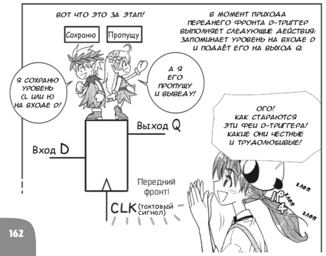
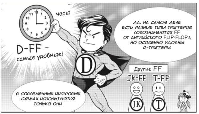
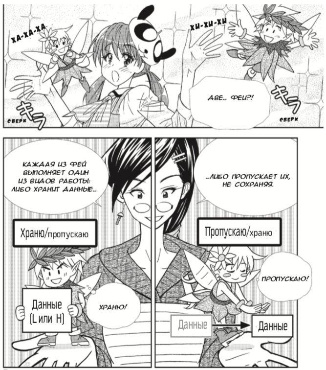
Manga avoids the mistakes of many of its predecessors. One of such mistakes was made by Charles Petzold in the book “Code”, which introduced sequential logic not on D-flip-flops controlled by a clock edge (edge-triggered D-flip-flop), but on D-flip-flops with level operation (snaps, level-sensitive D-latch), although then switched to the correct triggers. Probably, the error was due to the fact that Charles Petzold, who became famous as the author of the GUI programming books in Microsoft Windows, was not a practicing electronics developer, and for him the latches were “simpler” than the front-side triggers. The problem is that the latches are poorly compatible with static analysis of delays in logical synthesis, the main technology of designing digital circuits for the past 30 years. On-chip systems inside iPhone-type gadgets in 99% of cases, D-flip-flops are switched along the front, and latches are used only in very special cases. Giving newbies to build schemes with snaps means to mislead them.
In this sense, manga is better than Petzold. This is how elegantly manga explains the work of the two-stage D-flip-flop master slave, controlled by the clock edge. This is done with the help of the fairies "Hee-hee-hee" and the fairies "Ha-ha-ha":
Next, I highlight my comments in blue so that they do not merge with manga quotes:
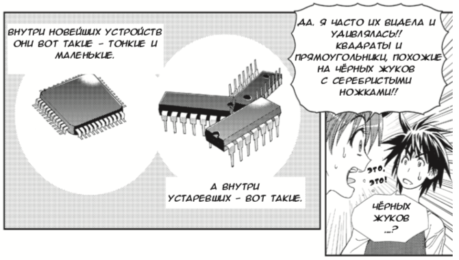
But let's start in order. Manga about digital circuits starts with microchips, and she immediately mentions both old microcircuits of a small degree of integration, with several logic elements, and modern ones, with millions and billions of transistors:
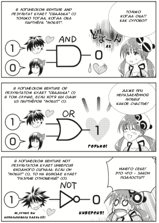
Manga explains the operation of logic elements with simple and pleasant for teenagers analogies:
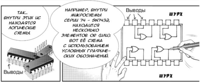
Why bother to mention low-level integrated circuits that were outdated 50 years ago? The fact is that despite the venerable age, exercises on a breadboard with such microchips are the most intuitive way to show students how the logic element works. To do this, you do not need to install software for modeling or synthesis for the FPGA. All you need is a breadboard, a 9 volt battery, a microcircuit, wires, LEDs and buttons:
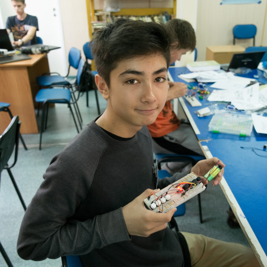
Some teachers of school circles believe that all such exercises should be replaced by Arduino. This opinion arose back in the 1970-1980s, when microcontrollers and embedded processors came into education. The typical schoolchild of 1988 could not spend hundreds of thousands of dollars for the production of his microcircuit at the factory, and old microcircuits of a small degree of integration in real industrial products were used less and less. Therefore, at the time, digital logic for schoolchildren was given up with a wave of arms and threw all their energy into programming training. Here is a Facebook comment describing this opinion these days:
However, 30 years later, everything changed again:
1. First, in the same 1988, the technology of designing microcircuits using logic synthesis appeared, from the code in hardware description languages - Verilog and VHDL.
2. At the same time, in the 1980s, programmable logic integrated circuits (FPGAs) arose — matrices of reconfigurable logic elements that can be used to build digital circuits simply by changing the contents of the configuration memory inside the FPGA.
3. In the 1990s, the teaching of HDL, logical synthesis and FPGA was included in the programs of all the electronics departments of Western universities, although in Russia and Ukraine, due to post-perestroika chaos, this process was slower.
4. In the 2000s, the speed of traditional processors ceased to grow, and marketers began to predict the fragmentation of the market for embedded processors (which happened - cloud, IoT), as well as the emergence of combinations of processors and specialized computers for various tasks (which happened - first fast mobile graphics, then specialized chips for mining cryptocurrency, computer vision and neural network accelerators).
5. Now, in 2010, FPGA board prices have dropped to the level when they became available to schoolchildren. At the same time, the industry requires a large number of new engineers to create huge chips with neural networks. Even if you are going to work all your life in programming, to understand new systems you need to know the principles of operation of the equipment: combinational and sequential schemes, finite automata, timing, pipelining, etc. Then you can figure out whether to process data with a conventional program or a hardware block.
So microcircuits of a small degree of integration allow “touching” hardware primitives directly. And immediately after explaining about the schemes of low degree of integration, the manga introduces both the hardware description languages and the FPGA:
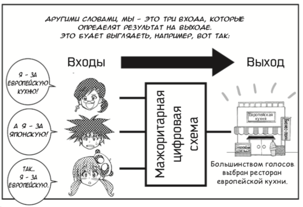
After describing the logical elements of the manga shows how to build a useful combinatorial voting scheme:
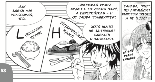
Then this scheme is optimized. In my opinion, manga spends too much time combinatorial optimization. But it is worth remembering that the Japanese wrote the manga, and they have a principle in culture 切磋琢磨 (takum) - polishing something (for example a sword) until it becomes perfect. Therefore, in manga there is both common sense optimization and Carnot diagram optimization. Logical synthesis of hardware description languages makes such optimizations automatically:
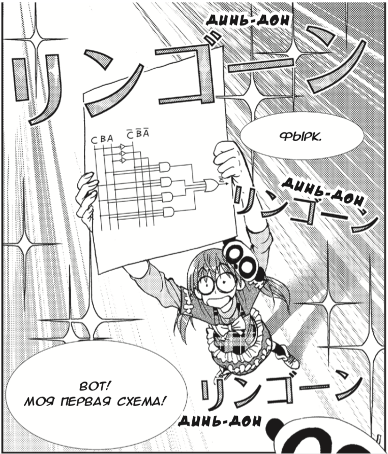
There is a romantic scheme in the manga, I mean the scene:

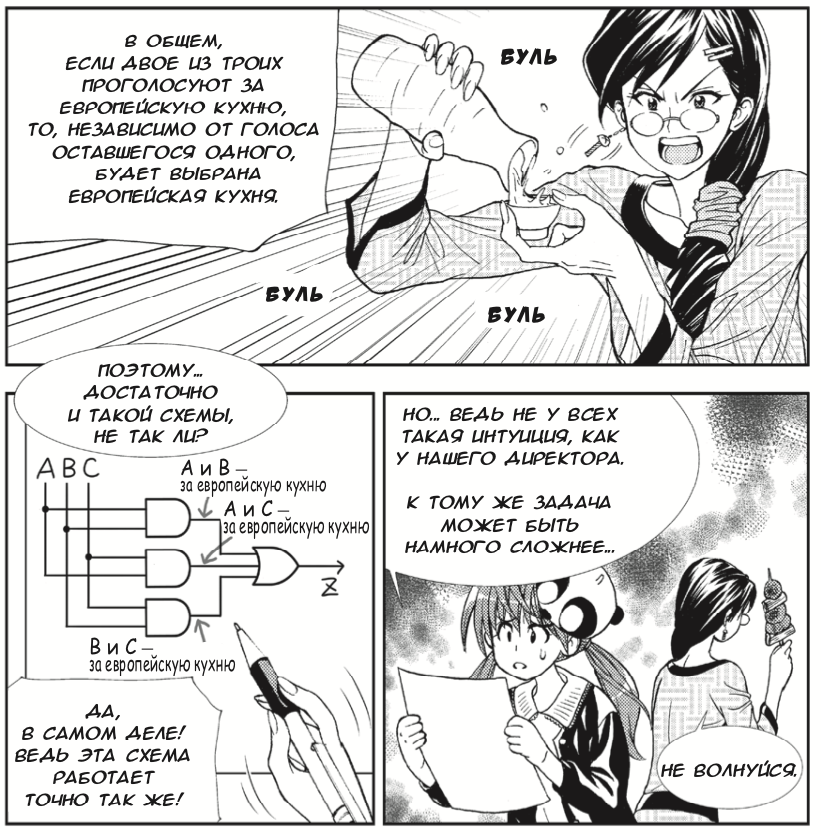
The majority voting scheme can be easily assembled on small-scale integrated circuits. At the same time, it is possible to argue that it is not very interesting to observe the combinatorial AND-OR-NOT-AND-OR-NOT elements on the breadboard, since the Boolean algebra is also explained in the usual programming lesson. It may be objected that although 7-year-old children can understand AND-OR-NOT, when trying to understand D-triggers, some students run across the mental barrier. In this case, a visual demonstration becomes more valuable.
Unfortunately, the student cannot D-triggers inside the FPGA with his hands directly. There are tens of thousands of them in FPGA. At Arduino, such an object does not arise at all. And on a motherboard with a microcircuit of a small degree of integration, the D-trigger can be felt like this:
But how to explain the sequential schemes and D-trigger manga. Note that the Japanese translator used the word “sequential” to translate “sequential”, although the term “sequential” is well established in Russian literature on digital circuitry:
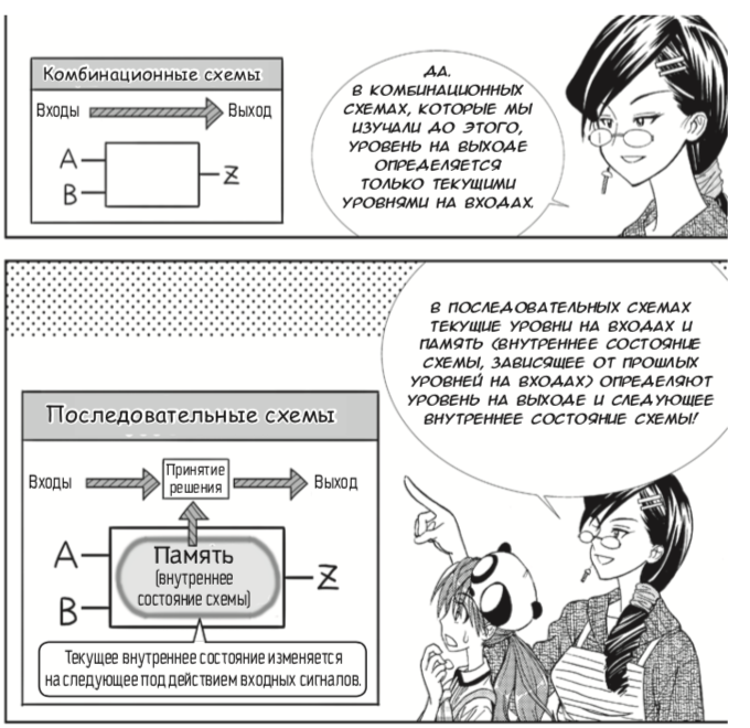
Here one could write more specifically that sequential circuits, as opposed to combinational ones, allow repeating actions and expect an event. In other words, they make the computer "smart." Without them, using a computer, one could only calculate the values of simple arithmetic expressions:
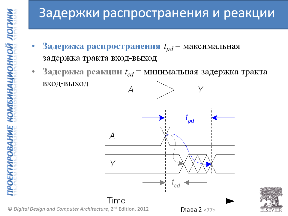
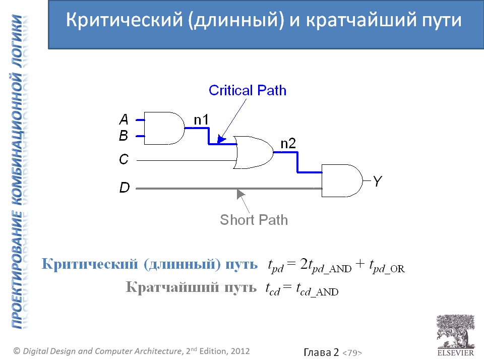
It’s a pity that the manga doesn’t tell anything about time delays in combination circuits and calculating the maximum clock frequency. It could be inserted here in this place:

I hope that this manga in Russia will have successors who will make some cartoon with Ivan Tsarevich and Vasilisa the Beautiful, who would introduce propagation delays and a critical path, for example, based on information from the Harris & Harris textbook. Here are the appropriate slides from the additional materials for the textbook:
Here is a slide in a straightforward form that now D-flip-flop is used for almost all elements of the state [except for cases that beginners do not encounter at all, for example, a latch to get a gated clock signal without impulse noise in the circuits for energy saving - level-sensitive D-latch for glitch-free gated clock used in low-power designs].
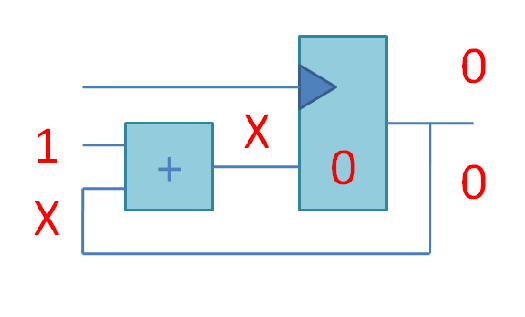
Recall that Petzold used D-latches for his introduction, which is wrong. But in this place not only Petzold makes mistakes. I once made a post in LiveJournal with such a picture of the counter below from the adder and D-flip-flop, where after that one Russian programmer from the state of Colorado argued for two days that it was easier to build counters on T-flip-flops. I told him that he correctly remembered T-flip-flops from his 1970s childhood, but now in the 21st century, iPhone developers are building D-flip-flop counters, because the situation of a T-flip-flop counter, in which the data signal is used as a clock signal , badly fits with the analysis of timing in chips of billions of transistors (if you disagree with me, please split my opinion with links to the ASIC libraries from TSMC, Synopsys Design Compiler, etc.):
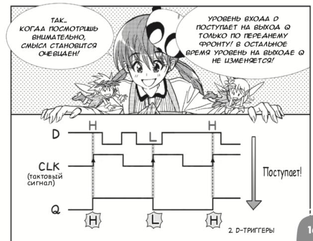
Now here is a series of pictures familiar to us about the work of the two-step (master-slave) D-flip-flop with fairies:
With an easy-to-understand time diagram, the data is recorded only at the moment of the positive D-flip-flop, the rest of the time they are ignored:
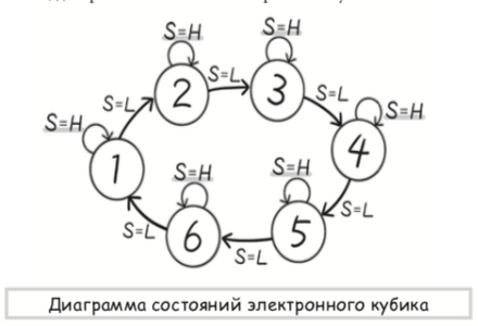
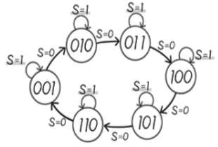
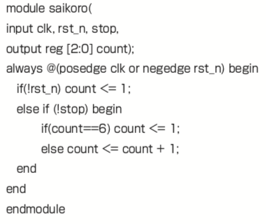
Now the manga turns to the example of using the D-trigger to build the simplest finite state machine - a device for throwing an electronic bone. Honestly, I’m not really excited about this part of the book. Let's say this, a degenerate finite-state machine, in which states go in a circle, stopped by one bit - the “stop” button. If there were several automata in the sample book, everything would be OK, but putting it as the only example is wrong. It does not show the entire class of problems that can be solved with the help of finite automata. Below I will show how I would add it.
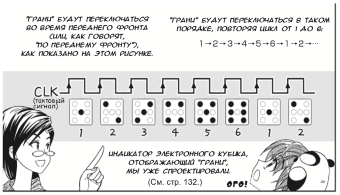
State diagram 0-1-2-3-4-5:
States in the binary representation, which are written in three D-flip-flops:
Combinatorial scheme, which receives the new state from the old:
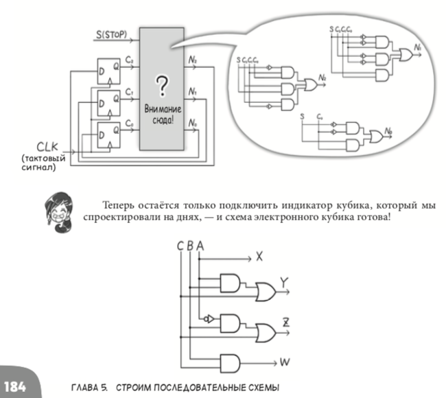
Finally, the manga shows how to design the same scheme not by drawing with the mouse on the screen, but by using synthesis from the Verilog hardware description language. Although this code looks similar to a code of a programming language like Pascal or Java, but this code has a completely different nature. The purpose of the code on the chain is to turn into a circuit with wires and transistors. A code in a programming language is compiled into a chain of instructions, zeros and ones that are stored in memory [it is clear that both Verilog and Java can be interpreted + the code on Verilog can turn into zeros and units for the configuration of FPGA + Java can be interpreted as Verilog and also become a scheme, but these are details that do not contribute to the initial understanding]:
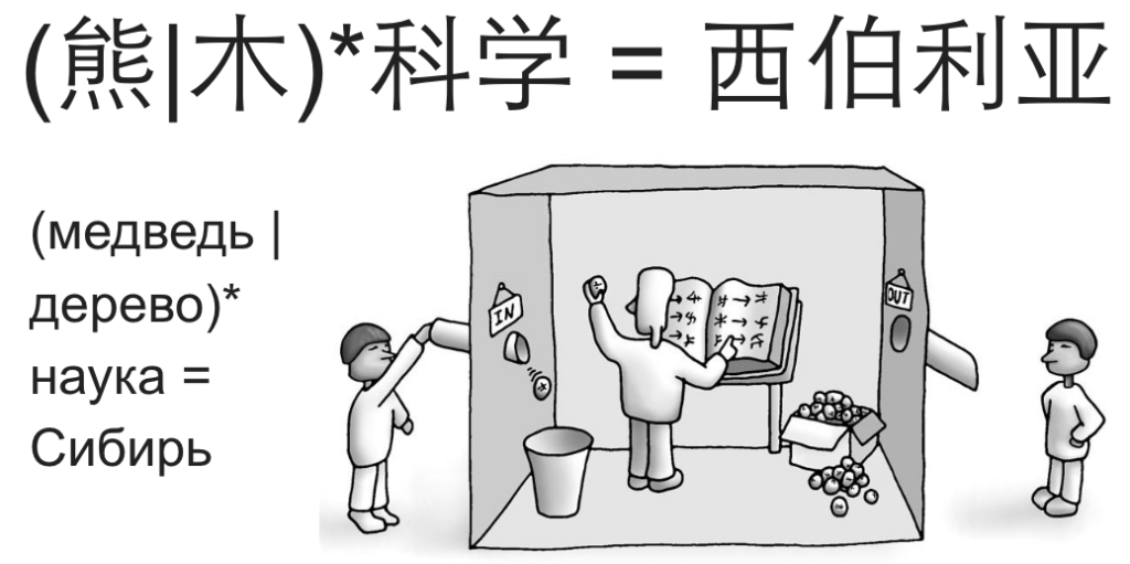
Now I kind of added an example about the finite automaton I. I would make a more interactive example of a finite state machine, for example using the analogy with the so-called “Chinese room”. Here is my description of the Chinese room, removed by the editor from my ten-year-old article in The New Times magazine (this magazine is not only about politics, it also has popular technology):
Here is its state diagram:
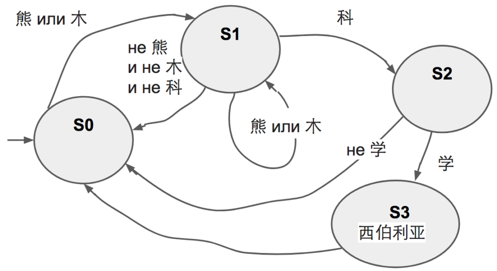
From this diagram it is possible to construct a circuit and implement it on the FPGA board.
The other day, I used excerpts from this manga by Amano Hideharu and Meguro Koji, when I lectured on Skype from California to 150 students from Kazan Innopolis. Students begin to study computer architecture, and they need to break through the barrier of initial misunderstanding of digital logic. For this, the manga is very good, especially if used in combination with textbooks such as Harris & Harris “Digital Circuit Design and Computer Architecture”.
Here is a video from this lecture:
Slides for this and the next lecture can be downloaded here:
http://bit.ly/2018-01-25-verilog-1-innopolis-yuri-panchul
http://bit.ly/2018-02-01-verilog-2 -innopolis-yuri-panchul
Now many readers of posts about FPGAs often have a question: “Why is this necessary, because Java has more jobs?”
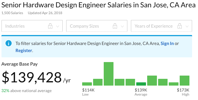
You can answer this: according to glassdoor, in San Jose, California, developers of digital circuits are appreciated more expensive than Java developers:

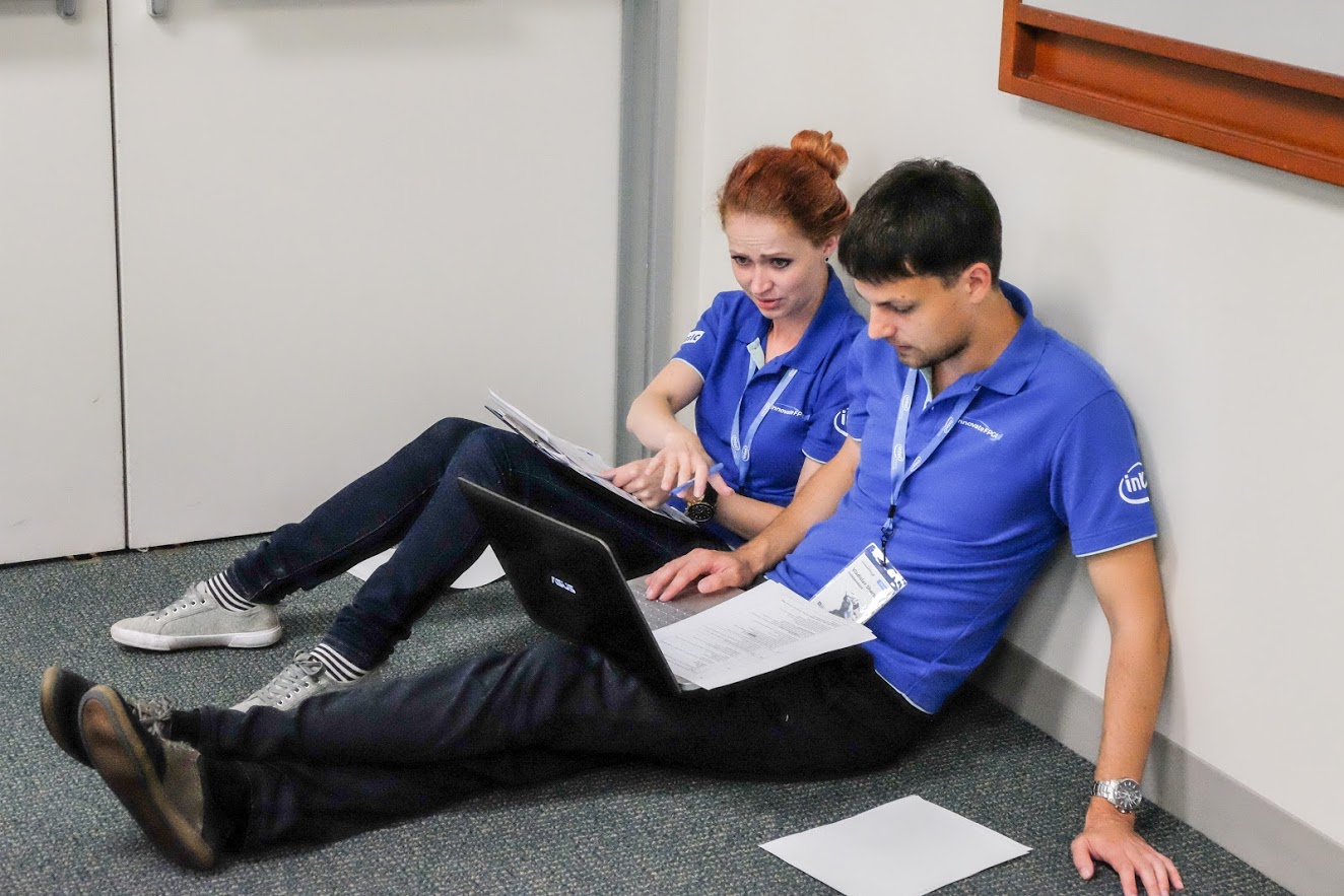
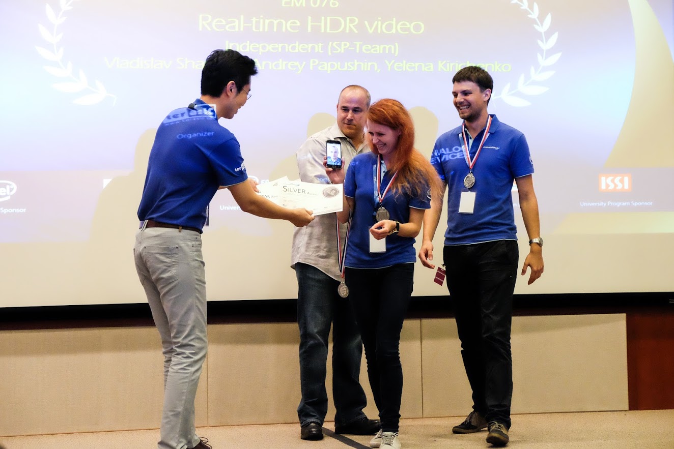
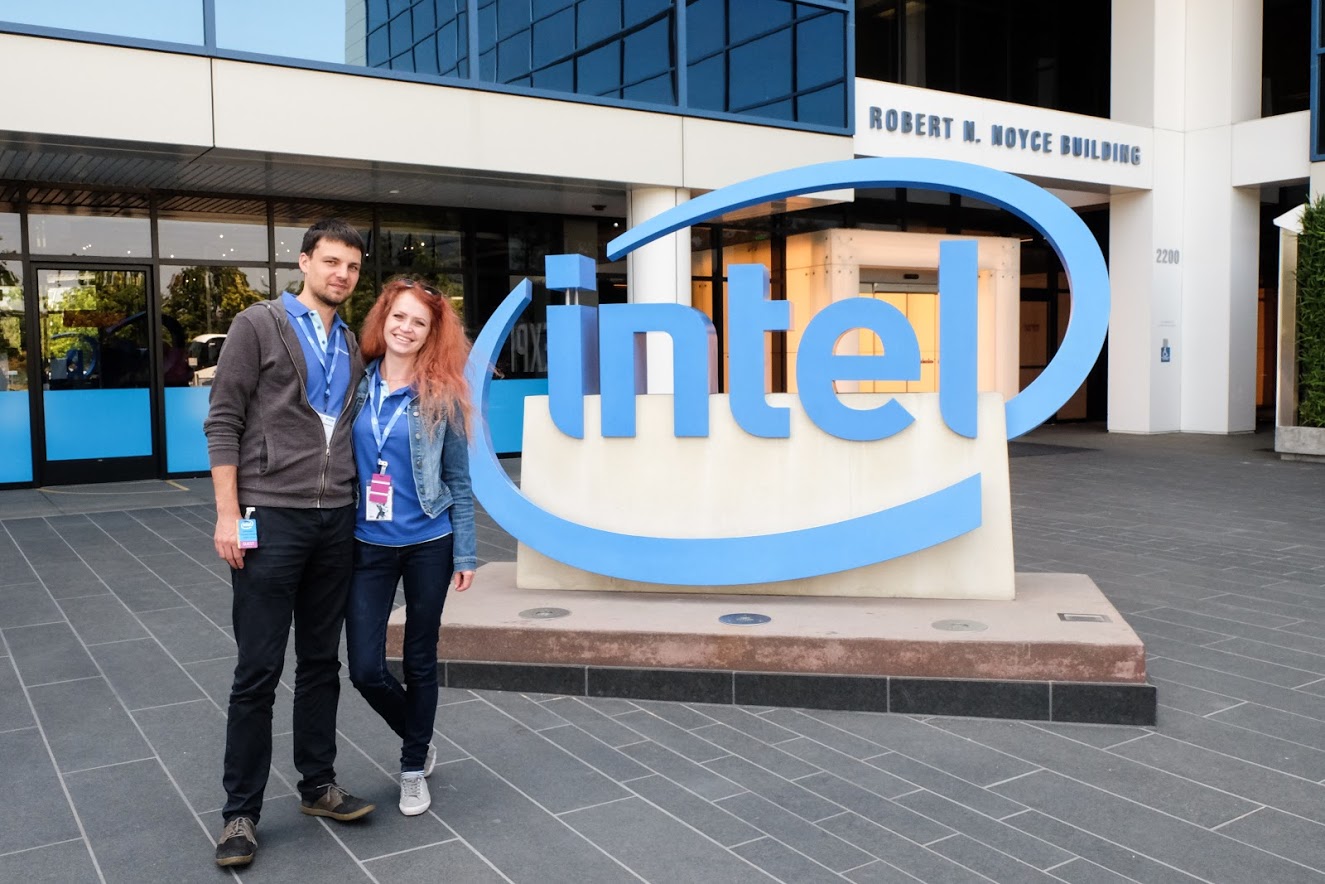
And if the reader says “What do I mean to San Jose? I’m in Russia and I’m not threatened to go to San Jose ”, then you can bring a fresh example that the newlyweds from St. Petersburg took first place in the Intel InnovateFPGA competition in Europe, after which they took second place in the world finals in San Jose. Here they sit in the Intel office in San Jose a few days ago. For having made a project on FPGA. Maybe for the project on Java Intel brought someone to San Jose with the award, but I personally do not know such examples.
Vladislav Sharshin, Andrey Papushin, Yelena Kirichenko - www.innovatefpga.com/cgi-bin/innovate/teams.pl?Id=EM076
Manga avoids the mistakes of many of its predecessors. One of such mistakes was made by Charles Petzold in the book “Code”, which introduced sequential logic not on D-flip-flops controlled by a clock edge (edge-triggered D-flip-flop), but on D-flip-flops with level operation (snaps, level-sensitive D-latch), although then switched to the correct triggers. Probably, the error was due to the fact that Charles Petzold, who became famous as the author of the GUI programming books in Microsoft Windows, was not a practicing electronics developer, and for him the latches were “simpler” than the front-side triggers. The problem is that the latches are poorly compatible with static analysis of delays in logical synthesis, the main technology of designing digital circuits for the past 30 years. On-chip systems inside iPhone-type gadgets in 99% of cases, D-flip-flops are switched along the front, and latches are used only in very special cases. Giving newbies to build schemes with snaps means to mislead them.
In this sense, manga is better than Petzold. This is how elegantly manga explains the work of the two-stage D-flip-flop master slave, controlled by the clock edge. This is done with the help of the fairies "Hee-hee-hee" and the fairies "Ha-ha-ha":
Next, I highlight my comments in blue so that they do not merge with manga quotes:
But let's start in order. Manga about digital circuits starts with microchips, and she immediately mentions both old microcircuits of a small degree of integration, with several logic elements, and modern ones, with millions and billions of transistors:
Manga explains the operation of logic elements with simple and pleasant for teenagers analogies:
Why bother to mention low-level integrated circuits that were outdated 50 years ago? The fact is that despite the venerable age, exercises on a breadboard with such microchips are the most intuitive way to show students how the logic element works. To do this, you do not need to install software for modeling or synthesis for the FPGA. All you need is a breadboard, a 9 volt battery, a microcircuit, wires, LEDs and buttons:
Some teachers of school circles believe that all such exercises should be replaced by Arduino. This opinion arose back in the 1970-1980s, when microcontrollers and embedded processors came into education. The typical schoolchild of 1988 could not spend hundreds of thousands of dollars for the production of his microcircuit at the factory, and old microcircuits of a small degree of integration in real industrial products were used less and less. Therefore, at the time, digital logic for schoolchildren was given up with a wave of arms and threw all their energy into programming training. Here is a Facebook comment describing this opinion these days:
However, 30 years later, everything changed again:
1. First, in the same 1988, the technology of designing microcircuits using logic synthesis appeared, from the code in hardware description languages - Verilog and VHDL.
2. At the same time, in the 1980s, programmable logic integrated circuits (FPGAs) arose — matrices of reconfigurable logic elements that can be used to build digital circuits simply by changing the contents of the configuration memory inside the FPGA.
3. In the 1990s, the teaching of HDL, logical synthesis and FPGA was included in the programs of all the electronics departments of Western universities, although in Russia and Ukraine, due to post-perestroika chaos, this process was slower.
4. In the 2000s, the speed of traditional processors ceased to grow, and marketers began to predict the fragmentation of the market for embedded processors (which happened - cloud, IoT), as well as the emergence of combinations of processors and specialized computers for various tasks (which happened - first fast mobile graphics, then specialized chips for mining cryptocurrency, computer vision and neural network accelerators).
5. Now, in 2010, FPGA board prices have dropped to the level when they became available to schoolchildren. At the same time, the industry requires a large number of new engineers to create huge chips with neural networks. Even if you are going to work all your life in programming, to understand new systems you need to know the principles of operation of the equipment: combinational and sequential schemes, finite automata, timing, pipelining, etc. Then you can figure out whether to process data with a conventional program or a hardware block.
So microcircuits of a small degree of integration allow “touching” hardware primitives directly. And immediately after explaining about the schemes of low degree of integration, the manga introduces both the hardware description languages and the FPGA:
After describing the logical elements of the manga shows how to build a useful combinatorial voting scheme:
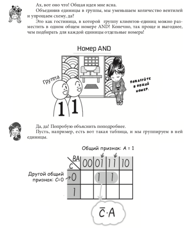
Then this scheme is optimized. In my opinion, manga spends too much time combinatorial optimization. But it is worth remembering that the Japanese wrote the manga, and they have a principle in culture 切磋琢磨 (takum) - polishing something (for example a sword) until it becomes perfect. Therefore, in manga there is both common sense optimization and Carnot diagram optimization. Logical synthesis of hardware description languages makes such optimizations automatically:
There is a romantic scheme in the manga, I mean the scene:
The majority voting scheme can be easily assembled on small-scale integrated circuits. At the same time, it is possible to argue that it is not very interesting to observe the combinatorial AND-OR-NOT-AND-OR-NOT elements on the breadboard, since the Boolean algebra is also explained in the usual programming lesson. It may be objected that although 7-year-old children can understand AND-OR-NOT, when trying to understand D-triggers, some students run across the mental barrier. In this case, a visual demonstration becomes more valuable.
Unfortunately, the student cannot D-triggers inside the FPGA with his hands directly. There are tens of thousands of them in FPGA. At Arduino, such an object does not arise at all. And on a motherboard with a microcircuit of a small degree of integration, the D-trigger can be felt like this:
But how to explain the sequential schemes and D-trigger manga. Note that the Japanese translator used the word “sequential” to translate “sequential”, although the term “sequential” is well established in Russian literature on digital circuitry:
Here one could write more specifically that sequential circuits, as opposed to combinational ones, allow repeating actions and expect an event. In other words, they make the computer "smart." Without them, using a computer, one could only calculate the values of simple arithmetic expressions:
It’s a pity that the manga doesn’t tell anything about time delays in combination circuits and calculating the maximum clock frequency. It could be inserted here in this place:
I hope that this manga in Russia will have successors who will make some cartoon with Ivan Tsarevich and Vasilisa the Beautiful, who would introduce propagation delays and a critical path, for example, based on information from the Harris & Harris textbook. Here are the appropriate slides from the additional materials for the textbook:
Here is a slide in a straightforward form that now D-flip-flop is used for almost all elements of the state [except for cases that beginners do not encounter at all, for example, a latch to get a gated clock signal without impulse noise in the circuits for energy saving - level-sensitive D-latch for glitch-free gated clock used in low-power designs].
Recall that Petzold used D-latches for his introduction, which is wrong. But in this place not only Petzold makes mistakes. I once made a post in LiveJournal with such a picture of the counter below from the adder and D-flip-flop, where after that one Russian programmer from the state of Colorado argued for two days that it was easier to build counters on T-flip-flops. I told him that he correctly remembered T-flip-flops from his 1970s childhood, but now in the 21st century, iPhone developers are building D-flip-flop counters, because the situation of a T-flip-flop counter, in which the data signal is used as a clock signal , badly fits with the analysis of timing in chips of billions of transistors (if you disagree with me, please split my opinion with links to the ASIC libraries from TSMC, Synopsys Design Compiler, etc.):
Now here is a series of pictures familiar to us about the work of the two-step (master-slave) D-flip-flop with fairies:
With an easy-to-understand time diagram, the data is recorded only at the moment of the positive D-flip-flop, the rest of the time they are ignored:
Now the manga turns to the example of using the D-trigger to build the simplest finite state machine - a device for throwing an electronic bone. Honestly, I’m not really excited about this part of the book. Let's say this, a degenerate finite-state machine, in which states go in a circle, stopped by one bit - the “stop” button. If there were several automata in the sample book, everything would be OK, but putting it as the only example is wrong. It does not show the entire class of problems that can be solved with the help of finite automata. Below I will show how I would add it.
State diagram 0-1-2-3-4-5:
States in the binary representation, which are written in three D-flip-flops:
Combinatorial scheme, which receives the new state from the old:
Finally, the manga shows how to design the same scheme not by drawing with the mouse on the screen, but by using synthesis from the Verilog hardware description language. Although this code looks similar to a code of a programming language like Pascal or Java, but this code has a completely different nature. The purpose of the code on the chain is to turn into a circuit with wires and transistors. A code in a programming language is compiled into a chain of instructions, zeros and ones that are stored in memory [it is clear that both Verilog and Java can be interpreted + the code on Verilog can turn into zeros and units for the configuration of FPGA + Java can be interpreted as Verilog and also become a scheme, but these are details that do not contribute to the initial understanding]:
Now I kind of added an example about the finite automaton I. I would make a more interactive example of a finite state machine, for example using the analogy with the so-called “Chinese room”. Here is my description of the Chinese room, removed by the editor from my ten-year-old article in The New Times magazine (this magazine is not only about politics, it also has popular technology):
In 1980, one of the critics of artificial intelligence, John Searle (John Searle) put forward an elegant argument, called the "Chinese room". Suppose that in the future there is a version of the program "Eliza", speaking Chinese so well that the Chinese could not distinguish a computer from a person. Now suppose that someone would rewrite this program into a thick book with mechanical instructions for a person - if you see hieroglyph A and saw hieroglyph B before, then pull out h character C from the drawer. Now we will put a certain person who does not know Chinese in a closed room with This book and will push him under the door signs with hieroglyphs containing questions in Chinese. Following the mechanical instructions from the book, the person will find in the box and push back the other signs with hieroglyphs. From the point of view of the external observer, the room will “understand” and “speak” in Chinese. But who is the carrier of this mind? After all, the performer does not understand Chinese?So here. For my own lectures and materials, I came up with an example in which the finite state machine (FSM) in response to a sequence of any number of hieroglyphs "bear" and "tree", with the final hieroglyph "science" - gives a sequence of hieroglyphs "Siberia". This is the simplest “Chinese room”:
John McCarthy and other veterans of artificial intelligence immediately declared that the mind and even consciousness would manifest itself in a “virtual personality” or in a “process” carried out in this room. One of the elegant arguments against John Searle was put forward by the philosophers Paul and Patricia Churchland. As we know from physics, Chirchlendy argued, light is an electromagnetic wave. Suppose that a skeptic begins to move the magnet with his hand, does not see the light, and begins to assert that light is impossible. In fact, in order to receive light, it is necessary to wave a magnet at a speed of 450 billion strokes per second. So the rational consciousness, asserted Cherchlendy, will arise in the "Chinese room" if the performer is sufficiently agile.
Interestingly, Ukrainian science fiction writer Anatoly Dneprov described an analogue of the “Chinese Room” back in the 1950s in the story “The Game”.
Here is its state diagram:
From this diagram it is possible to construct a circuit and implement it on the FPGA board.
The other day, I used excerpts from this manga by Amano Hideharu and Meguro Koji, when I lectured on Skype from California to 150 students from Kazan Innopolis. Students begin to study computer architecture, and they need to break through the barrier of initial misunderstanding of digital logic. For this, the manga is very good, especially if used in combination with textbooks such as Harris & Harris “Digital Circuit Design and Computer Architecture”.
Here is a video from this lecture:
Slides for this and the next lecture can be downloaded here:
http://bit.ly/2018-01-25-verilog-1-innopolis-yuri-panchul
http://bit.ly/2018-02-01-verilog-2 -innopolis-yuri-panchul
Now many readers of posts about FPGAs often have a question: “Why is this necessary, because Java has more jobs?”
You can answer this: according to glassdoor, in San Jose, California, developers of digital circuits are appreciated more expensive than Java developers:
And if the reader says “What do I mean to San Jose? I’m in Russia and I’m not threatened to go to San Jose ”, then you can bring a fresh example that the newlyweds from St. Petersburg took first place in the Intel InnovateFPGA competition in Europe, after which they took second place in the world finals in San Jose. Here they sit in the Intel office in San Jose a few days ago. For having made a project on FPGA. Maybe for the project on Java Intel brought someone to San Jose with the award, but I personally do not know such examples.
Vladislav Sharshin, Andrey Papushin, Yelena Kirichenko - www.innovatefpga.com/cgi-bin/innovate/teams.pl?Id=EM076
Only registered users can participate in the survey. Sign in , please.