We program nRF24LE1 through Raspberry PI and USBasp
Some time ago, inexpensive (from $ 6) nRF24LE1 radio modules with an integrated microcontroller were mentioned on the hub. On these radio modules, the guys from COOLRF planned to carry out their project, but in the end they moved to the more expensive Atmega128RFA1 chip, and as I understand it, they relegated to the background.
In this article, we will consider the possibility of flashing the radio module through Raspberry PI and USBasp as well as a couple of C code examples.
Description of nRF24LE1
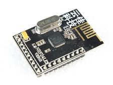
There are 3 options for the chip body: QFN24 (4 × 4 mm), QFN32 (5 × 5 mm), QFN48 (7 × 7 mm). And the peripherals of I2C, UART, SPI for each option are on different conclusions (see from 131 pages of the datasheet). Here I will consider the QFN32 variant and the technical specifications will apply to it.
The radio transmitting part is completely analogous to the “brainless” version of nRF24L01 +:
2.4 GHz, 125 channels. Supported speeds are 250kbps, 1Mbps and 2Mbps, etc.
The built-in 8051-compatible microcontroller has the following parameters:
- The clock frequency is 16 MHz. Frequency can be controlled (reduced to 125 kHz) in real time.
- Available flash memory for the 16kb program.
- RAM (RAM) memory 1 kb.
- 1 kb NVRAM (EEPROM memory)
- 7 pins support 6..12 bit ADC.
- Two eight-bit PWM (PWM) outputs.
- And there are also interfaces: I2C, UART, SPI.
- Supply voltage 1.9V ... 3.6V.
- Programming through slave SPI.
NRF24LE1 programming via Raspberry PI
It is possible to flash nRF24LE1 through the "native" programmer, which is relatively expensive - about $ 30 on Ebay. Of course, I did not like the price, and on the Internet, a variant of the programmer based on Raspberry PI github.com/derekstavis/nrf24le1-libbcm2835 was found . The source code of the programmer was slightly modified and Russified - I had to translate from Portuguese. The modified version can be downloaded from the link at the end of the article.
To program the radio module, you must connect the SPI pins according to the table:
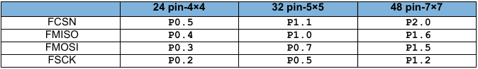
The PROG nRF24LE1 pin must be connected to the 24 GPIO pin on the Raspberry PI. We connect FCSN similarly to CE0 (pin 8). We tighten Reset to plus. Do not forget to connect GND to minus and VDD to + 3.3v.
The numbering card for the outputs of the radio module may be different (due to the different case of the microcircuit and the wiring of the printed circuit board) and usually this information can be found in the same place where the nRF24LE1 itself is sold, for example, when buying on Ebay, the numbering card is indicated on the product page.
To upload the firmware, we will use the compiled program nrf24le1 using the following commands:
- ./nrf24le1 test - displays test information nRF24LE1 (InfoPage).
- ./nrf24le1 write - will flash the main.bin file, which is in the same folder in nRF24LE1.
- ./nrf24le1 read - will create a firmware dump from nRF24LE1 under the name main-dump.bin.
NRF24LE1 programming via USBasp
After studying the firmware option via Raspberry PI, a simpler version was developed that can be implemented by any user programming AVR microcontrollers and armed with a USBasp programmer. I mentioned this programmer earlier , having implemented on it several different devices including nRF24L01-USB.
The programmer’s source code for Raspberry PI was used for this idea. And USBasp is reprogrammed into a USB-SPI adapter using the V-USB library.
USBasp-based programmer is relatively slow - all firmware is 16kb. "Poured" in 12 seconds, but this is offset by the price - still the price of this programmer is $ 3, not $ 30.
Connect nRF24LE1 to USBasp in the following order, according to the numbering of the ten pin connector:
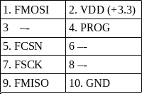
By the way, it is unclear whether the nRF24LE1 pins are tolerant to 5 Volts and whether resistor dividers are needed to match the levels between nRF24LE1 and USBasp. As a result, I did not use dividers and did not get any negative consequences - you can also not set dividers, but at your own peril and risk. For example, the nRF24L01 + terminals are tolerant and can be connected to 5 Volt microcontrollers.
All programming steps are similar to programming through Raspberry PI.
We write the first programs on nRF24LE1
To write the program, I used the free cross-platform SDCC compiler sdcc.sourceforge.net .
nRF24LE1 has an SDK where the basic functions for working with the microcontroller are described. This SDK is checked and corrected by me. It is compiled from several sources.
Here is an example of a blinking LED
#include <stdint.h>#include <stdio.h>//подключение необходимых функций SDK:#include "src/gpio/src/gpio_pin_configure.c"#include "src/gpio/src/gpio_pin_val_clear.c"#include "src/gpio/src/gpio_pin_val_set.c"#include "delay.h"#include "src/delay/src/delay_us.c"#include "src/delay/src/delay_s.c"#include "src/delay/src/delay_ms.c"voidmain()
{
 // мигаем портом P0_0
	gpio_pin_configure(GPIO_PIN_ID_P0_0, // укажем необходимые параметры
			GPIO_PIN_CONFIG_OPTION_DIR_OUTPUT |
			GPIO_PIN_CONFIG_OPTION_OUTPUT_VAL_CLEAR |
			GPIO_PIN_CONFIG_OPTION_PIN_MODE_OUTPUT_BUFFER_NORMAL_DRIVE_STRENGTH);
		while(1)
	{
gpio_pin_val_set(GPIO_PIN_ID_P0_0); // установка в 1
	 delay_ms(500);
gpio_pin_val_clear(GPIO_PIN_ID_P0_0); //установка в 0
	 delay_ms(500);
	}
}
An example of smooth ignition of an LED using a PWM pin
#include <stdio.h>//подключение необходимых функций SDK:#include "delay.h"#include "src/delay/src/delay_us.c"#include "src/delay/src/delay_s.c"#include "src/delay/src/delay_ms.c"#include "src/pwm/src/pwm_configure.c"#include "src/pwm/src/pwm_start.c"voidmain()
{
int i=0;
  // делитель на 10 , битность 8
  pwm_configure(PWM_CONFIG_OPTION_PRESCALER_VAL_10 || PWM_CONFIG_OPTION_WIDTH_8_BITS);
	//main program loopwhile(1)
	{
pwm_start(PWM_CHANNEL_0,i);
	  i++;
	 delay_ms(200);
	 if (i>255) i=0;
	}
}
At the moment I am completing an example for working with nRF24L01-USB. Already implemented reading the DHT22 sensor and load management over the air. In the future I plan to make an approximate analogue of the Arduino RF24 library - it remains to complete a couple of functions.
In general, after programming on AVR microcontrollers, programming nRF24LE1 seemed to me almost a little complicated.
UPD: I forgot to mention that the compiler creates a hex file, and programmers need a binary. To convert the file, you can use the hex2bin utility . You can write the hex2bin -p 00 main.ihx command to the make file.
What improvised pieces of iron can still be redone for nRF24LE1 programming?
Any similar Raspberry PI mini computer, such as Cubieboard, will do.
You can implement the programmer on Arduino. Perhaps I’ll deal with this option.
Any microcontroller with hardware USB support, for example, STM-ki.
Source codes and example:
Programmer on Raspberry PI
Programmer on USBasp (updated 5.02.14)
SDK
led_delay
Datashit
Maybe I missed something and there were questions - write in the comments.