First steps with the Stellaris LM4F120 launchpad evaluation board
The Stellaris LM4F120 board was lying around in my desk, which I decided to finally deal with. We will write a program that turns on / off the LEDs installed on the board in response to pressing the buttons on the board.
I must say right away that I’m a little tough with electronics, so the article will express my opinion on how it works, which may not coincide with reality. I’m very bad with terminology, so if you know the correct term, please correct.
With compilers and IDEs, Texas Instruments provides a choice : their own Eclipse-based Code Composer Studio (can be installed either separately or as a plug-in for the already installed Eclipse, if any), IAR Embedded Workbench, Keil and Mentor Graphics Sourcery CodeBench:
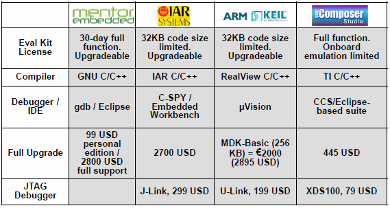
The free version of CCS is fully functional and I will use it. Using the link above, you can download the “CD”, which is hiding behind the EK-LM4F120XL-CCS part number, on which there will be everything that is needed for development, but the contents of the archive are somewhat outdated and, it seems, are not being updated. But you can download everything individually:
Code Composer Studio , StellarisWare is hiding behind part number SW-EK-LM4F120XL here , Stellaris ICDI drivers , LMFlash programmer , Evaluation board User's Manual , Datasheet. After installing StellarisWare in the directory where you installed it, you can find the docs subdirectory with the documentation. There, the main interest is the file SW-DRL-UG-9453.pdf (the numbers may differ depending on the SW version) - documentation on the functions provided by the SDK (also, if you look at SW-EK-LM4F120XL-UG-9453.pdf, you can to find high-level functions for working with LEDs and buttons right away, but this is not the way of a real Jedi: do we want to understand what is going on inside?) I
must say that TI underwent some renaming , and the LM4F120H5QR microcontroller used in the board became TM4C1233H6PM, respectively, at the moment, to search for information, one should use Use the second name.
Texas Instruments Video Lecturesabout the board and printed materials to them;
Connect the board to the computer:
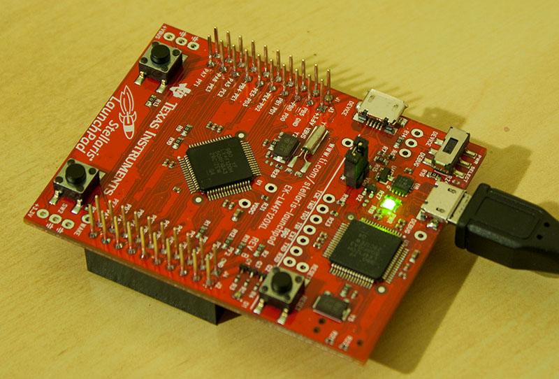
We connect the USB cable to the debugger port, make sure that the power switch (next to the USB port) is in the “debug” position. If everything was done correctly, except for the green power LED, the LED next to the “reset” button should light up, and after 5 seconds, start to overflow with different colors (unless, of course, you had time to flash something different from the factory firmware).
A note about Windows 8.1. This operating system by default does not allow downloading unsigned drivers, which makes it impossible to install ICDI drivers. It is treated as follows: press Win + I → Power, hold Shift and click Restart, wait, a menu with repair options will appear, select Troubleshoot → Advanced options → Startup settings → Restart. After rebooting, a menu will appear in which to select "Disable driver signature enforcement".
So, we have installed everything you need. It's time to write. Create a project in CCS: File → New → CCS Project. We configure it similarly to the picture:

We will receive the project in which there will be at once two files with source codes: empty
Immediately configure the paths for searching header files and libraries, go to the menu Project → Properties, then:
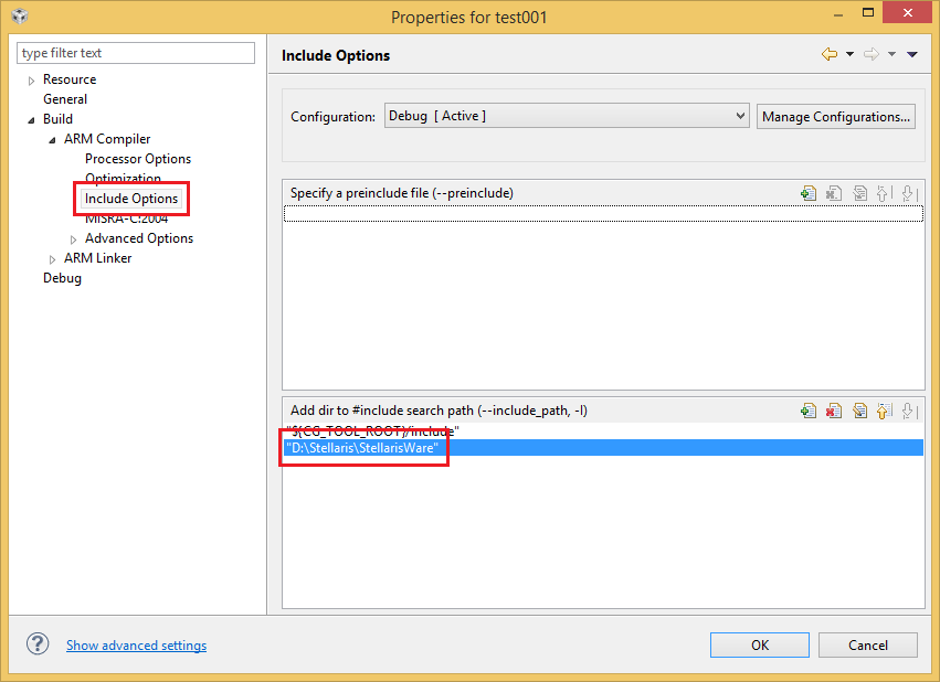
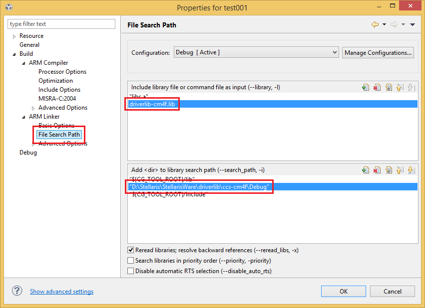
Replace the paths with yours, of course.
Add
If it doesn’t work, we repair it, if it works, you can start doing something useful.
First of all, you need to configure the frequency at which our microcontroller will work. The maximum frequency with which it can work is 80 MHz, but less is possible. Section 5.2.5 of the data sheet tells us how to adjust the frequency and is scary in Figure 5-5:
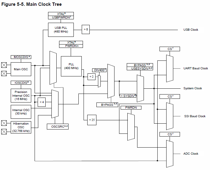
At the moment, we are interested in the “System clock” output. According to the data sheet, the following can be used as a clock source:
Of these sources, two are external, in relation to the microcontroller (Main OSC and Hibernation OSC), the rest are inside it.
The divider designated as SYSDIV in the diagram can be tuned to a 1x – 64x frequency reduction. If PLL is used as the source, an additional 2-bit frequency divider controlled by the DIV400 bit can be used (by default enabled). A PLL requires a master pulse generator. Its frequency can vary widely, but it must be specified during initialization. Using PLL is the only way to start the microcontroller at the maximum frequency, so we will use it (although for our purposes such a crazy frequency is not needed). For PLL clocking, both an external crystal and an internal one can be used.
StellarisWare offers a feature
To begin with, we decide whether we use PLL (
If we use PLL, you need to choose who will be the master oscillator: Main OSC (
If we do not use PLL, you must specify the source:
And finally, you need to configure the divider. There are macros from
Total, the call
or so:
Or whatever you like.
It's time to make a program, the result of which can be seen. The documentation for the board has a circuit for turning on the LEDs:


Those. LEDs are connected to the legs of the 1-3 GPIO port F (if anyone knows why the resistor between the base and the emitter of the transistor - please enlighten, and why is it not indicated?). The GPIO port has eight legs, each of which can be individually configured as an input or as an output. Writing and reading is done from all legs at once by writing or reading the register
So, to light the LED, you need to set a high level of voltage on the corresponding leg. Those. write 1 to the corresponding bit. Usually, to change the state of a bit, you need to read the status of the register, set the values of the desired bits and write the received value back. Memory operations are slow, therefore, the microcontroller developers provide the opportunity to do with one record (without preliminary reading): the register is accessed not at one address, but over a range of 1024 bytes starting with the base address. Bits 2–9 of the address contain a mask of bits whose values need to be updated. Those. if we want to write 1 to bit No. 1, we need to take the appropriate mask: 0x02, shift it to the left by 2 bits and add the resulting value to the base address - we get the address,
The function to set the desired bits could look like this:
StellarisWare provides a function
Only one thing is missing: you need to turn on the port and configure the legs to which the LEDs are connected as outputs. For those who want to do without an SDK, the process is described in section 10.3 of the microcontroller's data sheet. With StellarisWare, this is done by calls
Function
Two buttons are connected to legs 0 and 4 of the GPIO port F according to this scheme:

It can be seen from the diagram that pressing the button connects the foot to the ground, and in the non-pressed state the foot is not connected anywhere. This is bad; when you try to read from an unconnected leg, anything can be read. We need to ensure that the supply voltage is connected when the button is not pressed. This will help us pull-up (pull-up), which, in fact, connects the foot to the power supply through the resistor, so that when the button is not pressed on it will receive power through the pull-up, and when pressed, the current from it will go to the ground, those. the released button will be read as a unit in the port, pressed - as zero.
So, set legs 0 and 4 to the input, enable pull-up:
The function
Putting it all together:
This wonderful program and a fee for 12 bucks, finally, allows you to do the same as a simple schematic of less than a dozen parts, worth 10 rubles, congratulations!
I must say right away that I’m a little tough with electronics, so the article will express my opinion on how it works, which may not coincide with reality. I’m very bad with terminology, so if you know the correct term, please correct.
Training
First, you need to install the necessary software for development:- Compiler and development environment
- SDK (StellarisWare)
- Debug Module Drivers
- Firmware program
- Documentation
With compilers and IDEs, Texas Instruments provides a choice : their own Eclipse-based Code Composer Studio (can be installed either separately or as a plug-in for the already installed Eclipse, if any), IAR Embedded Workbench, Keil and Mentor Graphics Sourcery CodeBench:
The free version of CCS is fully functional and I will use it. Using the link above, you can download the “CD”, which is hiding behind the EK-LM4F120XL-CCS part number, on which there will be everything that is needed for development, but the contents of the archive are somewhat outdated and, it seems, are not being updated. But you can download everything individually:
Code Composer Studio , StellarisWare is hiding behind part number SW-EK-LM4F120XL here , Stellaris ICDI drivers , LMFlash programmer , Evaluation board User's Manual , Datasheet. After installing StellarisWare in the directory where you installed it, you can find the docs subdirectory with the documentation. There, the main interest is the file SW-DRL-UG-9453.pdf (the numbers may differ depending on the SW version) - documentation on the functions provided by the SDK (also, if you look at SW-EK-LM4F120XL-UG-9453.pdf, you can to find high-level functions for working with LEDs and buttons right away, but this is not the way of a real Jedi: do we want to understand what is going on inside?) I
must say that TI underwent some renaming , and the LM4F120H5QR microcontroller used in the board became TM4C1233H6PM, respectively, at the moment, to search for information, one should use Use the second name.
Texas Instruments Video Lecturesabout the board and printed materials to them;
Connect the board to the computer:
We connect the USB cable to the debugger port, make sure that the power switch (next to the USB port) is in the “debug” position. If everything was done correctly, except for the green power LED, the LED next to the “reset” button should light up, and after 5 seconds, start to overflow with different colors (unless, of course, you had time to flash something different from the factory firmware).
A note about Windows 8.1. This operating system by default does not allow downloading unsigned drivers, which makes it impossible to install ICDI drivers. It is treated as follows: press Win + I → Power, hold Shift and click Restart, wait, a menu with repair options will appear, select Troubleshoot → Advanced options → Startup settings → Restart. After rebooting, a menu will appear in which to select "Disable driver signature enforcement".
Very first program
So, we have installed everything you need. It's time to write. Create a project in CCS: File → New → CCS Project. We configure it similarly to the picture:
We will receive the project in which there will be at once two files with source codes: empty
main.cand lm4f120h5qr_startup_ccs.c. The second file contains boilerplate code for initializing the interrupt table and stub functions for handling interrupts. Immediately configure the paths for searching header files and libraries, go to the menu Project → Properties, then:
Replace the paths with yours, of course.
Add
#includeto main.cand check that everything compiles:#include
#include
#include
#include
#include
int main(void)
{
return 0;
}
If it doesn’t work, we repair it, if it works, you can start doing something useful.
Working frequency
First of all, you need to configure the frequency at which our microcontroller will work. The maximum frequency with which it can work is 80 MHz, but less is possible. Section 5.2.5 of the data sheet tells us how to adjust the frequency and is scary in Figure 5-5:
At the moment, we are interested in the “System clock” output. According to the data sheet, the following can be used as a clock source:
- Precision Internal OSC 16 MHz
- Main OSC (on this board is designated as Y1, and has a frequency of 16 MHz)
- Internal OSC 30 kHz
- Hibernation OSC (32.768 kHz) - Y2 on the board
- Pll
- Precision Internal OSC through 4 divider
Of these sources, two are external, in relation to the microcontroller (Main OSC and Hibernation OSC), the rest are inside it.
The divider designated as SYSDIV in the diagram can be tuned to a 1x – 64x frequency reduction. If PLL is used as the source, an additional 2-bit frequency divider controlled by the DIV400 bit can be used (by default enabled). A PLL requires a master pulse generator. Its frequency can vary widely, but it must be specified during initialization. Using PLL is the only way to start the microcontroller at the maximum frequency, so we will use it (although for our purposes such a crazy frequency is not needed). For PLL clocking, both an external crystal and an internal one can be used.
StellarisWare offers a feature
SysCtlClockSetto configure everything related to the System clock in one fell swoop. To do this, a bunch of flags are fed to her input: To begin with, we decide whether we use PLL (
SYSCTL_USE_PLL) or something else ( SYSCTL_USE_OSC) - the BYPASS flag on the diagram. If we use PLL, you need to choose who will be the master oscillator: Main OSC (
SYSCTL_OSC_MAIN) or Precision Internal OSC ( SYSCTL_OSC_INT). If we use Main OSC, we must specify its frequency (in our case SYSCTL_XTAL_16MHZ). If we do not use PLL, you must specify the source:
- Precision Internal OSC -
SYSCTL_OSC_INT - Precision Internal OSC through 4 - Divider
SYSCTL_OSC_INT4 - Main OSC -
SYSCTL_OSC_MAIN - Internal OSC -
SYSCTL_OSC_INT30 - Hibernation OSC -
SYSCTL_OSC_EXT32
And finally, you need to configure the divider. There are macros from
SYSCTL_SYSDIV_1to for this SYSCTL_SYSDIV_64. If you use PLL, you can optionally use macros SYSCTL_SYSDIV_2_5(/2.5) - SYSCTL_SYSDIV_63_5(/63.5). For reasons unknown to me, for a call, the SysCtlClockSetPLL frequency is considered equal to 200 MHz, i.e. in order to operate at a frequency of 80 MHz, a divider of 2.5 must be specified. Total, the call
SysCtlClockSetmay look like this: // используем PLL, задающий генератор - Main OSC с частотой 16 МГц, используем делитель 2.5, итоговая частота 80 МГц
SysCtlClockSet(SYSCTL_USE_PLL | SYSCTL_SYSDIV_2_5 | SYSCTL_XTAL_16MHZ | SYSCTL_OSC_MAIN);
or so:
	// используем PLL, задающий генератор - Precision Internal OSC, используем делитель 2.5, итоговая частота 80 МГц, отключаем Main OSC
	SysCtlClockSet(SYSCTL_USE_PLL | SYSCTL_SYSDIV_2_5 | SYSCTL_OSC_INT | SYSCTL_MAIN_OSC_DIS);
Or whatever you like.
Blinking LEDs
It's time to make a program, the result of which can be seen. The documentation for the board has a circuit for turning on the LEDs:
Those. LEDs are connected to the legs of the 1-3 GPIO port F (if anyone knows why the resistor between the base and the emitter of the transistor - please enlighten, and why is it not indicated?). The GPIO port has eight legs, each of which can be individually configured as an input or as an output. Writing and reading is done from all legs at once by writing or reading the register
GPIODATAmapped to memory (respectively, we read / write one byte - the state of all legs). There are two ways to access the port: through the Advanced Peripheral Bus (APB) or through the Advanced High-performance Bus (AHB). The first method is “old” and slow, the second is modern and fast. Honestly, what difference between them in terms of programming I do not know (at least the base addresses for the ports differ), I used APB, the base address for port F is 0x40025000.So, to light the LED, you need to set a high level of voltage on the corresponding leg. Those. write 1 to the corresponding bit. Usually, to change the state of a bit, you need to read the status of the register, set the values of the desired bits and write the received value back. Memory operations are slow, therefore, the microcontroller developers provide the opportunity to do with one record (without preliminary reading): the register is accessed not at one address, but over a range of 1024 bytes starting with the base address. Bits 2–9 of the address contain a mask of bits whose values need to be updated. Those. if we want to write 1 to bit No. 1, we need to take the appropriate mask: 0x02, shift it to the left by 2 bits and add the resulting value to the base address - we get the address,
The function to set the desired bits could look like this:
void pinWrite(unsigned int base, unsigned char pins, unsigned char value)
{
	*((unsigned char *)base + ((unsigned int)pins << 2)) = value;
}
StellarisWare provides a function
GPIOPinWritewith the same signature that does the same. Only one thing is missing: you need to turn on the port and configure the legs to which the LEDs are connected as outputs. For those who want to do without an SDK, the process is described in section 10.3 of the microcontroller's data sheet. With StellarisWare, this is done by calls
SysCtlPeripheralEnableand GPIOPinTypeGPIOInput/ GPIOPinTypeGPIOOutput.#include
#include
#include
#include
#include
const unsigned int LED_RED = 0x02;
const unsigned int LED_GREEN = 0x08;
const unsigned int LED_BLUE = 0x04;
const unsigned int LEDS_ALL = 0x02 | 0x08 | 0x04;
int main(void)
{
SysCtlClockSet(SYSCTL_USE_PLL | SYSCTL_SYSDIV_2_5 | SYSCTL_XTAL_16MHZ | SYSCTL_OSC_MAIN);
SysCtlPeripheralEnable(SYSCTL_PERIPH2_GPIOF);
SysCtlDelay(2);
GPIOPinTypeGPIOOutput(GPIO_PORTF_BASE, LEDS_ALL);
const unsigned long int delay = 80000000 / 3 / 2; // 80 МГц, 3 такта на единицу задержки, 1/2 секунды нужная задержка
while (1)
{
GPIOPinWrite(GPIO_PORTF_BASE, LEDS_ALL, LEDS_ALL);
SysCtlDelay(delay);
GPIOPinWrite(GPIO_PORTF_BASE, LEDS_ALL, 0);
SysCtlDelay(delay);
}
return 0;
}
Function
SysCtlDelaydoes niterations empty loop, allowing you to make the delay desired length. Each iteration lasts 3 clock cycles of the processor. We compile, run (F11 in CCS, then you will need to press F8, because by default at the beginning of the program there is an implicit breakpoint). The LED on the board should start blinking white with a period of one second. If instead of the LEDS_ALLthird argument of the first call GPIOPinWritepass, for example, LED_GREENblinks green.Buttons!
Two buttons are connected to legs 0 and 4 of the GPIO port F according to this scheme:
It can be seen from the diagram that pressing the button connects the foot to the ground, and in the non-pressed state the foot is not connected anywhere. This is bad; when you try to read from an unconnected leg, anything can be read. We need to ensure that the supply voltage is connected when the button is not pressed. This will help us pull-up (pull-up), which, in fact, connects the foot to the power supply through the resistor, so that when the button is not pressed on it will receive power through the pull-up, and when pressed, the current from it will go to the ground, those. the released button will be read as a unit in the port, pressed - as zero.
So, set legs 0 and 4 to the input, enable pull-up:
	GPIOPinTypeGPIOInput(GPIO_PORTF_BASE, GPIO_PIN_0 | GPIO_PIN_4);
	GPIOPadConfigSet(GPIO_PORTF_BASE, GPIO_PIN_0 | GPIO_PIN_4, GPIO_STRENGTH_2MA, GPIO_PIN_TYPE_STD_WPU);
The function
GPIOPadConfigSetallows you to set the current that the foot (2, 4 or 8 mA) and its mode can give out. It is worth noting that the microcontroller has protection against changing the settings of some legs of some GPIO ports (those that can be used for the JTAG / SWD port (bits 0-3 of port C) or for the input of an unmasked interrupt - NMI (7 bits of port D and 0 bits port F)): you can change the pull-up / pull-down settings for these legs only if GPIOCR1. is written in the register . You GPIOCRcan write to the register only if a GPIOLOCKspecial “magic number” is written in the register . Putting it all together:
#include
#include
#include
#include
#include
const unsigned int LEDS_ALL = GPIO_PIN_1 | GPIO_PIN_2 | GPIO_PIN_3;
const unsigned int SW1 = GPIO_PIN_0;
const unsigned int SW2 = GPIO_PIN_4;
void crSet(unsigned int base, unsigned char value);
int main(void)
{
	int led = 2;
	SysCtlClockSet(SYSCTL_USE_PLL | SYSCTL_SYSDIV_2_5 | SYSCTL_XTAL_16MHZ | SYSCTL_OSC_MAIN);
	SysCtlPeripheralEnable(SYSCTL_PERIPH2_GPIOF);
	SysCtlDelay(2);
	GPIOPinTypeGPIOOutput(GPIO_PORTF_BASE, LEDS_ALL);
	GPIOPinTypeGPIOInput(GPIO_PORTF_BASE, SW1 | SW2);
	HWREG(GPIO_PORTF_BASE + GPIO_O_LOCK) = GPIO_LOCK_KEY_DD;
	crSet(GPIO_PORTF_BASE, 1);
	GPIOPadConfigSet(GPIO_PORTF_BASE, SW1 | SW2, GPIO_STRENGTH_2MA, GPIO_PIN_TYPE_STD_WPU);
	crSet(GPIO_PORTF_BASE, 0);
	HWREG(GPIO_PORTF_BASE + GPIO_O_LOCK) = 0;
	while (1)
	{
		unsigned int state = ~GPIOPinRead(GPIO_PORTF_BASE, SW1 | SW2);
		led = ((state & SW1) << 1) | ((state & SW2) >> 1);
		GPIOPinWrite(GPIO_PORTF_BASE, LEDS_ALL, led);
	}
	return 0;
}
void crSet(unsigned int base, unsigned char value)
{
	unsigned long v = (HWREG(GPIO_PORTF_BASE + GPIO_O_CR) & 0xFFFFFF00) | value;
	HWREG(base + GPIO_O_CR) = v;
}
This wonderful program and a fee for 12 bucks, finally, allows you to do the same as a simple schematic of less than a dozen parts, worth 10 rubles, congratulations!