3G internet in the distance from the base station with a plate and a coffee can
Hello to all residents of Habr!
The essence of this article is to show another option to catch the E / M wave in the relative outback for the needs of Internet access.
If somewhere exactly such a design has already flickered, you are welcome to link, it will be interesting to compare and communicate.
I will present the material in a narrative form, I hope I don’t bother anyone with this, all sorts of terms, if anyone does not know, and other details can be safely skipped, the essence of the post will not change much.
Formulation of the problem
The Internet is a useful and necessary thing, and I think it's hard to argue with that. And if there are no problems in the city with the Internet, then in the village where I often have to go for family reasons, there are certain problems. There is a private wooden house a la “hut” (location: RB), from the Internet in my neighborhood 3 operators provide access, but the maximum is only EDGE technology. The nearest two base stations (BS) are about 3.5 and 7 km. Between the house and the BS forest, but not close. EDGE would have been enough, but judging by the speed, loading these stations from other neighboring villages is such that you can "hide in potatoes."
The option to buy a ready-made solution fell away immediately for reasons of sports interest.
Inspired at one of the forums by the guys ’successful experience, they used a satellite dish (aka“ offset mirror antenna ”) and the 3G modem itself in focus, decided to simulate something like that and twist it.
I must say right away that I wanted to throw the antenna with the modem into the attic, so as not to spoil the appearance of the house (more on this below).
Shopping, modeling, measurements
The first thing I was looking for a bigger mirror. I agreed with the toad on the Ukrainian Kharkov mirror with a diameter of about 85 cm, because the price tag is already taking off non-linearly for those that I saw more than 1 m.
On a map of the coverage area of the operators, I found that to the nearest point with 3G about 21 km. The relief to the BS is not a mountain, but again, there is enough forest.
The first experience was in the winter. There was no bracket, so I tried to set the antenna as it should. Tentatively set to the proposed BS with 3G, but no matter how I turned the mirror itself and did not orient the modem in the focus zone, nifig, sorry, it did not work out. Although the beam width (BF) (if simpler, the "beam width") at 2.1 GHz is quite wide, this is not a digital satellite TV on the Ku band, where you can try to get into this satellite.
The reasons are as follows. As far as possible, the daylight in the modem is calculated isotropic, therefore, part of the power goes not to the mirror, but to the opposite side, and the antenna itself on the modem board in its ability to catch something weak leaves much to be desired, this is logical. The BS and the antenna are separated by a wooden roof shield, which also gives a certain attenuation. I even came across interesting literature on this topic, mainly on the subject of wood drying. Quite entertaining, but with a bunch of formulas from electrodynamics that characterize the dielectric properties of "wood." Of the useful things, first of all, it is that the attenuation coefficient depends on the orientation of the fibers in the board with respect to the polarization of the wave. I didn’t think about it before, although it’s also logical.
But here, no luck: the boards in the board are all vertically arranged - the maximum attenuation.
In general, there was a desire to mess around, but there was no opportunity (in the attic with a laptop on the battery for a long time to sit) and health (temperature -> to the street => hands freeze).
A little in frustrated feelings, I decided to act according to the classical scheme: a homemade irradiator is in the focus of the mirror, from a modem to an irradiator - a coaxial cable.
As for the irradiator, there were thoughts about what to take: a kind of rectangular waveguide, or round one. He stopped at a regular tin can. In the west it is called "Cantenna". Nothing original, the Internet lacks experience in this miracle. I tried, like some, simply to shove the modem into the old jar at the point where the probe is usually placed in the waveguide and thus irradiate the mirror, also failed.
As a result, having determined the diameter of the can with the condition for the propagation of one mode at its frequency (~ 2.1 GHz) in a round waveguide, I went to the store with a ruler (!) Behind the can. Prior to this, I had to dig a bit in the internet at what frequencies we have deployed UMTS. Taki found the necessary 10 cm in diameter. I bought two, for which I received verbal lyuli from my relatives, although I bought, sort of, for my own. Coffee was not cheap.
In addition, I had to buy a SMA connector for a nut so that the bank could be disconnected from the modem.
He modeled the antenna system and the irradiator on a computer separately, and went to shred the jar. Here you need to be quite careful with the size: the characteristics are sensitive to misses.
The figure below shows a model of a can in which a copper tube (a plump cylinder tapering to the bottom), sealed at the output of the SMA connector, is located at random.

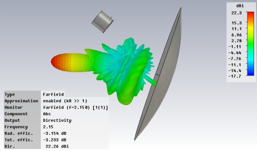
Here's what happened with the simulation (CST).
Gain based on simulation results: 22 dBi.
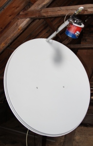
The following is a general view of the entire offset antenna, which is familiar to many, + 3D NAM.


The characteristics of the antenna itself were not measured, only the SWR on the SMA connector directly on the bank. On the graph, curves S11 (reflection coefficient in dB). The green curve is an experiment (in theory, it can still be used at frequencies 3.4, 4.5, 5.5 GHz ;-)).
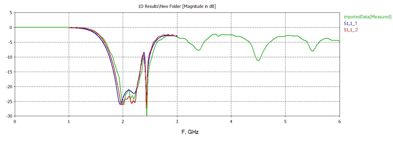
Pleasantly surprised that coincided quite accurately. For me, the SWR is good: all the power from the aperture of the antenna goes into the cable (and vice versa).
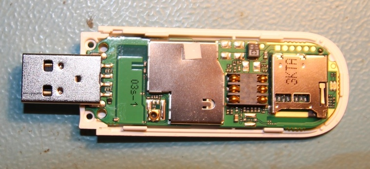
But then the saddest thing began. At first, I wanted to use the Huawei E303 I bought once in a store, soldering to it directly with a cable, because modem without external connector.
Finding a rather small connector on the board (U.FL, most likely), I tried to solder the end of the RG174 cable in its place, because I didn’t even try to plug the cable connector in our retailers. The idea was, frankly, idiotic - little experience, although he used a soldering station. The RF path of the modem was covered - it became a kind of USB-microSD adapter. In the photo there is still a target (a photo for reference to someone, maybe interesting, I was looking for exactly E303 on the Internet, I did not find it).
So to him: how much I suffered with him with switching to modem mode, and not a network card, in order to see the signal level in numbers (it even came to using linux). Well, somehow the numbers turned out.
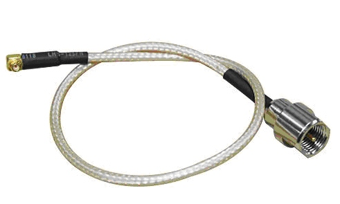
After a while, kind people gave Huawei e173 with a connector, but with a broken USB plug. I am glad that now I am unsoldering from the old connector and soldering into the new one, I find that the contact area on the board on the signal pair is broken, and under the microscope I could see only the jumper point (via). "Lucky." But the world, again, is not without good people: MGTF was “soldered” to this jumper (surprisingly, the solder was seized) and the connector was soldered. The modem is working. Happiness was full of pants. Now I needed a CRC-9 connector. After a trip to the radio market in Minsk, the only thing I found was only the “CRC-9 - FME” cable (the same as in the photo below).
I had to re-solder FME to SMA.
Testing
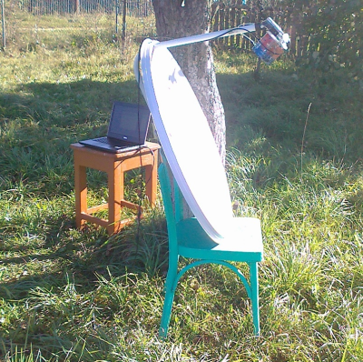
Finally, in the summer, it's time to test what happened. In the garden, under the apple trees.
On the left in the photo, blue-red is a can of coffee, the modem is attached to it with adhesive tape, and the cable mentioned above is connected from the connector on the modem to the connector on the bank. On the right in the photo is another angle. Behind the knoll is a continuous forest.
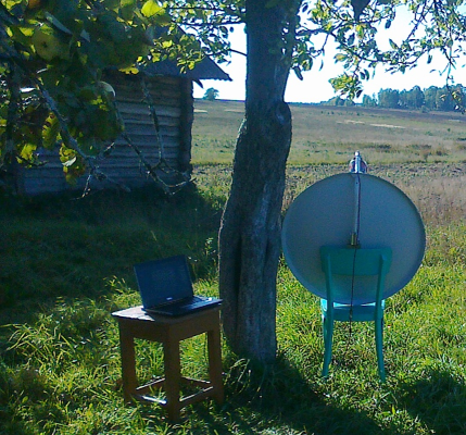
Turning the antenna, I found two points. In one, the signal is worse (the result of the MDMA program), at the level of -103 dBm (the forest is closer, or the channel is worse, or the BS antennas shine weaker in my direction, did not understand), and the second is better -93dBm. I note that this is all from ground level! In the second photo you can see the direction to the second BS (the distance is slightly more than 20 km, if you believe the non-monitors, for which I thank them separately).
 |  |
Speed test from under a tree

By the way, it’s very funny to talk on Skype in video mode, sitting under an apple tree.
It remains to pile it all up in the attic. But it remains to solve another problem. I did not want to drive 220V into the attic in order to put a router to power the modem. Since long USB cables are not cheap (I needed> 7 m), I had to solder a USB extension cable using a twisted pair cable (I had a chance to buy SSTP 6 cat, I’m terribly glad I used it for greater reliability, although it’s also not cheap). As for how to make a USB extension cable out of twisted pair, there is enough information on the network. Drilling a hole in the ceiling, he lowered the cable into the house. Well, there, as a fantasy allows, even Wi-Fi.
The signal in the attic floats from -87dBm to -93dBm. But this is uncritical.
On the left is a speed test in the attic of the entire system. And on the right is what the modem gave by itself in the attic of nearby BS (2G) (even ICQ slowed down).
 |  |
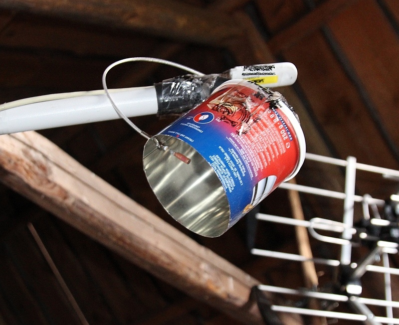
Photo from the attic. On top is another antenna - DMV (DVB-T). Part of the photo, where the window is, is the shield mentioned above.

And the photo of the can is a little closer. Anyone got a Nobel Prize for scotch, or not ?! If not, then this is a terrible mess!
I hope that someone will find the information useful in thinking and will bring civilization closer to your forgotten corner of God. I ask for constructive criticism in the studio. If you have questions, I will be happy to answer.