Another article on web traffic caching
Introduction, or why do we need another article on WCCP?
About the organization of transparent caching web traffic using the protocol WCCP much has been written, including a nice article on Habré . Typically, these articles discuss a circuit similar to that shown in the figure on the left.

At first glance, the solution has solid advantages: the implementation is simple, caching is absolutely transparent for users, and if a proxy server fails, requests will automatically be redirected directly.
But is WCCP always going smoothly? And if not, how to deal with emerging issues?
For example, almost all articles mention that the cache server should be in the same segment as users, but the reasons for this are not specified. But what if the security policy requires that all servers are in the perimeter network and are protected by a firewall (ME)?
Recently, I had to deal with a similar requirement when installing a caching server in a network of a telecom operator, a simplified diagram of which is shown in the title picture on the right.
If readers are interested in what problems they encounter when implementing such schemes, and how to get around the limitations, welcome.
Theory - Standards and Implementation Features
First, a little theory. WCCP protocol is designed to redirect traffic (not just web) in real time. Initially, the protocol was developed by Cisco, then it became an open standard used by most vendors.
Today, version 2, which is in the status of Internet-Draft and described by draft-mclaggan-wccp-v2rev1-00, is relevant .
Let us dwell on several important points in the operation of this protocol (see the figure).
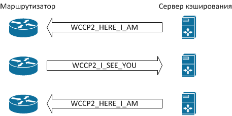
All WCCP messages are UDP packets with a destination port number of 2048. The messaging order is as follows:
- If the server is ready to process traffic caching requests, it sends WCCP2_HERE_I_AM messages.
- The router sends the server a WCCP2_I_SEE_YOU message containing information about the settings, in particular, the “Receive ID” field.
- The server in response sends another message WCCP2_HERE_I_AM, which contains the “Receive ID” field with the same value as in the previous step, thereby confirming that it is ready to work with the router.
- Having received such a message, the router understands that from this moment user requests to websites should be redirected to the cache server.
The system is ready to go. The WCCP2_HERE_I_AM and WCCP2_I_SEE_YOU messaging process is repeated periodically (by default, once every 10 seconds), and if the router does not receive a response from the cache server, the latter is excluded from the process.
In reality, the protocol is somewhat more complicated, it provides authentication, various redirection algorithms, etc., but we will consciously omit details that are unimportant for further understanding. Interested readers can find them in the corresponding draft, the link to which is given above.
This implementation contributes to the fault tolerance of the solution - if the caching server fails and stops sending WCCP2_HERE_I_AM messages, the router will stop trying to forward packets and start sending them directly to the Internet. After the service is restored, the WCCP2_HERE_I_AM / WCCP2_I_SEE_YOU messaging process will be repeated, and the caching scheme will start working again.
For users, such a refusal is either completely invisible, or it may look like a one-time “Unable to connect” message, which will disappear after the page is reloaded in the browser.
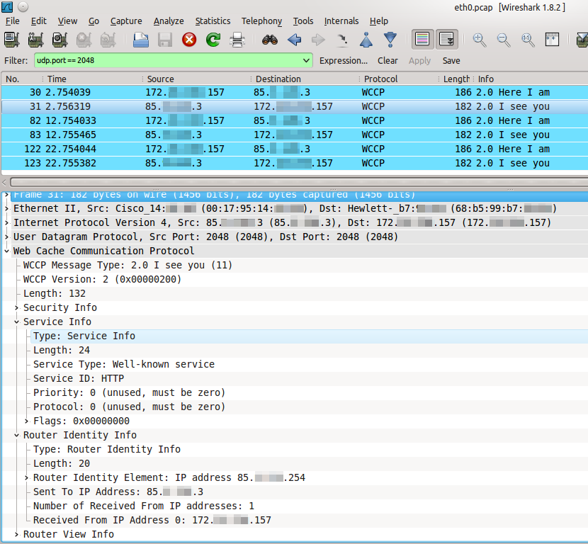
In Wireshark, the WCCP messaging process looks like the one in the following figure. Pay attention to the Time column. The traffic image was taken from a real-world system, so the IP addresses are truncated for security purposes.
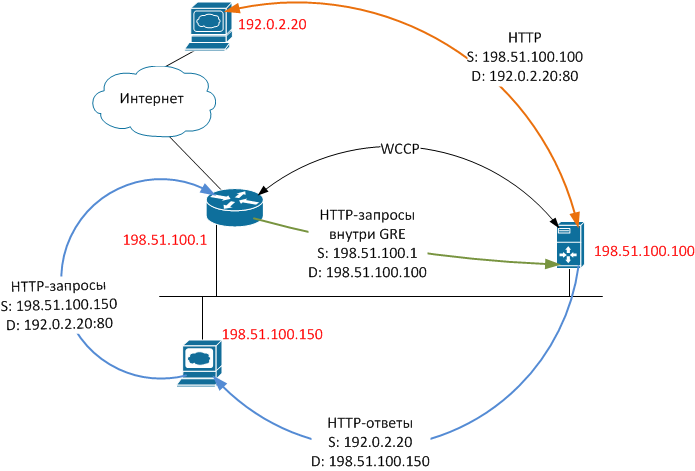
Let's see what happens when a client tries to get data from a web server. For clarity, we will assign specific IP addresses to the hosts using the special ranges allocated for use in the examples , and for simplicity, we will exclude all unnecessary functionality (NAT, firewalling, etc.) from consideration.
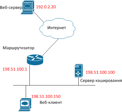
- The user browser initiates a TCP session by sending a packet with SRC IP 198.51.100.150, DST IP 192.0.2.20, DST TCP port 80, TCP SYN flag.
- Having received such a packet, the router does not send it further to the Internet, but packs it entirely in the GRE packet and sends it to the cache server. The GRE packet has, respectively, SRC IP 192.51.100.1 and DST IP 198.51.100.100. In Wireshark, it looks like the following figure.
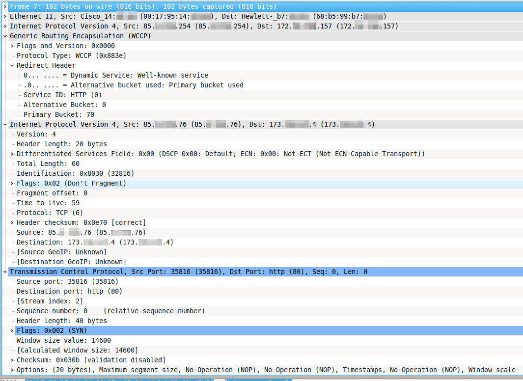
- Having received such a packet, the cache server first of all decides whether it will process this packet. If not, the packet is sent back to the router for normal forwarding through the same GRE tunnel, and the algorithm ends. If yes, then the server proceeds to the next step.
- The caching server establishes a connection with the web server on its behalf, for which it sends a packet with SRC IP 198.51.100.100, DST IP 192.0.2.20, DST TCP port 80, TCP SYN flag.
- In response, the web server sends a packet with SRC IP 192.0.2.20, SRC TCP port 80, DST IP 198.51.100.100, TCP SYN / ACK flags, that is, until everything goes in accordance with the usual start of a TCP session using the three- way handshake.
- The caching server, receiving a response from the web server, does two things:
- sends a packet to the web server with SRC IP 198.51.100.100, DST IP 192.0.2.20, DST TCP port 80, ACK flag, that is, it continues the normal TCP session, which for the web server looks like it was accessed by a regular Client with IP address 198.51.100.100.
- sends a packet to the web client with SRC IP 192.0.2.20, SRC TCP port 80, DST IP 198.51.100.150, TCP SYN / ACK flags, that is, for the client the situation looks as if the web server responded directly to it. Remember this moment, it is key for further understanding.
- sends a packet to the web server with SRC IP 198.51.100.100, DST IP 192.0.2.20, DST TCP port 80, ACK flag, that is, it continues the normal TCP session, which for the web server looks like it was accessed by a regular Client with IP address 198.51.100.100.
- So, we have two established TCP sessions, one between the client and the cache server, and the other between the cache server and the web server. The cache server receives content from the web server in the usual way, broadcasts it to the client, simultaneously storing it in memory or (and) on disk.
Upon subsequent access to the same content, the caching server, subject to certain conditions, will be able not to pump its web server again, but to give it to the web client on its own.
The described algorithm is schematically shown in the figure.
Pay attention to several important points:
- Packets inside the GRE tunnel are sent primarily from the router to the cache server (unless the cache server cannot process the packet and sends it back to the router for normal forwarding).
- In the opposite direction, i.e., from the cache server to the web client, packets are sent directly, generally bypassing the router.
- The cache server does not set the packets for the web client to its own address, but the address of the website to which the request was made.
Such an implementation of the protocol significantly reduces the load on the router, because it only has to redirect traffic from the web client to the web server, the volume of which is usually small. Traffic from a web server, the volume of which is usually significant, is not subjected to any complex processing - it is simply routed.
But such an implementation creates asymmetric traffic, which, in turn, creates the difficulties discussed in the next section.
Practice - fighting routers and firewalls
We modify the previous scheme - we put the cache server behind the firewall:

We will assume that we use popular equipment - the Cisco router with Cisco IOS software version 12.3 and higher, the Cisco ASA firewall with software version 8.2 and higher, the Linux-based cache server (RHEL distribution or CentOS) Squid caching software.
How to configure everything in this case? Assume that the basic functionality is already configured, that is, the web client and the cache server are able to access resources on the Internet. Let's start by setting up WCCP on Cisco.
We will carry out preparatory work, for which we will create two access lists:
ip access-list standard l_wccp_service
 permit 203.0.113.100
ip access-list extended l_wccp_redirect
 permit tcp host 198.51.100.150 any eq www
The first determines which caching servers are allowed to receive WCCP2_HERE_I_AM messages.
The second determines what traffic needs to be wrapped to the cache server.
We will configure WCCP and enable it on the interface looking towards internal users, i.e., having the address 198.51.100.1. For definiteness, let it be FastEthernet0 / 0):
ip wccp web-cache redirect-list l_wccp_redirect group-list l_wccp_service
interface FastEthernet0/0
 ip wccp web-cache redirect in
On the firewall, we allow WCCP and GRE packets to be exchanged between the router and the cache server.
access-list l_wccp extended permit gre host 198.51.100.1 host 203.0.113.100
access-list l_wccp extended permit udp host 198.51.100.1 host 203.0.113.100
access-group l_wccp in interface outside
Now configure the caching server. First, install and configure squid, for which, using your favorite text editor, open the /etc/squid/squid.conf file and make sure that it contains the following lines:
# /etc/squid/squid.conf
http_port 3128 transparent
wccp2_router 198.51.100.1
wccp2_forwarding_method 1
wccp2_return_method 1
wccp2_assignment_method hash
wccp2_service standard 0
We will create a tunnel interface, for which, again, in our favorite editor, create the file / etc / sysconfig / network-scripts / ifcfg-tun0 with the following contents:
# /etc/sysconfig/network-scripts/ifcfg-tun0
DEVICE=tun0
BOOTPROTO=none
ONBOOT=yes
TYPE=GRE
PEER_OUTER_IPADDR=198.51.100.1
PEER_INNER_IPADDR=192.168.168.1
MY_INNER_IPADDR=192.168.168.2
IP addresses PEER_INNER_IPADDR and MY_INNER_IPADDR can be absolutely any - nothing will be routed through this tunnel in the normal way. Instead, all TCP traffic arriving at it with DST port 80 will be wrapped on squid using iptables. Assuming that squid is responding on port 3128, we’ll raise the tunnel interface and wrap up the necessary traffic on squid:
/etc/sysconfig/network-scripts/ifup tun0
iptables -t nat -A PREROUTING -i tun0 -p tcp -m tcp --dport 80 -j DNAT --to-destination 203.0.113.100:3128
/etc/init.d/iptables save
Verify that the cache server has registered with the router:
cisco# show ip wccp
Global WCCP information:
    Router information:
        Router Identifier:                   198.51.100.1
        Protocol Version:                    2.0
    Service Identifier: web-cache
        Number of Service Group Clients:     1
        Number of Service Group Routers:     1
        Total Packets s/w Redirected:        175623
          Process:                           0
          Fast:                              0
          CEF:                               175623
        Redirect access-list:                l_wccp_redirect
        Total Packets Denied Redirect:       113892411
        Total Packets Unassigned:            20590
        Group access-list:                   l_wccp_service
        Total Messages Denied to Group:      26558
        Total Authentication failures:       0
        Total Bypassed Packets Received:     0
Here we can expect an unpleasant ambush: a router usually has several interfaces with different IP addresses. And nothing prevents him from sending WCCP2_I_SEE_YOU packets with SRC IP of one interface, and GRE packets with SRC IP of another interface.
In some, but not all versions of the firmware of Cisco IOS routers, the “ip wccp source-interface” command is provided, which allows you to hard-set the interface whose IP address will be used as SRC IP for all packets related to the WCCP subsystem .
If your router supports this command, you're in luck. Run it:
ip wccp source-interface FastEthernet 0/0
If, in response to such a command, the router generates something like “Syntax error,” we proceed as follows - run a diagnostic on the ME, and on the cache server some network analyzer (at least tcpdump) and find out from which IP addresses it comes WCCP packets, and with which GRE packets.
Next, in the squid settings, specify the first IP address, in the tunnel interface and iptables settings - the second. We modify the access lists on the ME accordingly.
To prevent the IP address from which WCCP packets arrive between the interfaces during subsequent reconfigurations of the router, you can create the loopback interface on the last one. In this case, WCCP will use the largest IP address among all loopback interfaces to send its packets.
interface lo0
 ip address 198.51.100.20 255.255.255.255
Verify that the redirect works. First, make sure that the packet counters in the access lists created earlier grow:
cisco# show access-list l_wccp_redirect
Extended IP access list l_wccp_redirect
    10 permit tcp host 198.51.100.150 any eq www (2399 matches)
Then open an arbitrary web page in the browser of the client machine. And surely nothing will work out for us. When trying to figure it out, we will probably find messages in the logs of the firewall about this type:
%ASA-4-313004: Denied ICMP type=0, from 192.0.2.20 on interface dmz to 198.51.100.150: no matching session
If we try to google, the first link will tell us something about asymmetric routing. Let’s figure out what this means.
The Cisco ASA firewall is a device that operates in Stateful Inspection mode , that is, in order to pass a packet with TCP SYN / ACK flags from the cache server to the client, it is necessary that the corresponding packet with the TCP SYN flag from the client to the website went forward through the same ME.
In this case, the ME will understand that the client has initiated a TCP session, will create the appropriate internal structures, and will begin to correctly monitor the state of this TCP session.
In our scheme, the initiating SYN packet passes through the ME a) inside the GRE tunnel and b) "as if in the wrong direction."
Accordingly, the ME does not start a TCP session in its connection table and cannot understand that the session has started, and its packets must be skipped.
What to do in such a situation? If it is impossible to connect the caching server bypassing the ME, it only remains to disable the check for an open TCP session for packets arriving from the DMZ side.
In Cisco ASA, the disable verification feature is called TCP bypass . The function has limitations:
- Doesn't work on Cisco ASA with software version 8.2 or earlier.
- There is no known (at least, we were not able to find) way of organizing both the client zone and the DMZ on the same Cisco ASA model ME — IP address translations do not work predictably.
So, enable the TCP bypass function:
access-list l_bypass extended permit tcp any eq www host 198.51.100.150
class-map c_bypass
 match access-list l_bypass
policy-map p_bypass
 class c_bypass
  set connection advanced-options tcp-state-bypass
service-policy p_bypass interface dmz
The l_bypass access list must have a range of client IP addresses.
Now everything should work. At least it worked for us.
Conclusion
The article is based on the experience of implementing the function of caching web traffic in the network of a small telecom operator, and once again illustrates two old principles in the work of a network engineer:
- Do not neglect the standards and descriptions of the protocol;
- If you don’t understand what’s going on, don’t be too lazy, connect a network analyzer.
Successful testing and implementation! And let now and always your channels transport as little as possible extra traffic.