Dell u2412m: getting rid of PWM without losing the ability to adjust brightness
This article will tell you the sequence of necessary actions in order to forget once and for all about pulse-width modulation (PWM) in your monitor. You will work behind the monitor with the brightness that will be comfortable for your eyes, but with only one difference - the backlight of your monitor will not generate PWM. Everything is very simple! The main thing is to be able to work with a soldering iron ...
The steps in this article will void the warranty on the monitor. The author is not responsible for force majeure or other circumstances resulting in damage to your property used in attempts to repeat the steps below.
Well, after much deliberation and accumulation of money, I finally became the copyright holder of a number of Dell u2412m monitors. For those who are interested, revision A0, January 2013. After reading a few forums that discuss this monitor, I came to the conclusion that many potential buyers are worried about the presence of PWM. Yes, indeed, in the first revisions, users complained about PWM, but it was clear from the reviews that in subsequent revisions this problem was fixed. Since I am not the copyright holder of the first revisions, but also the electrical circuit diagram (in order to compare the differences in electronics), from my own experience I can assume that a simple banal step was taken - increasing the frequency of the PWM.
Nevertheless, people continue to ask, asking the same question again and again - “I think I’ll take U2412M, but it’s embarrassing to have PWM. Tell me, will his eyes hurt a lot? ”
As for me, after spending a week at the monitor with the presence of PWM, getting used to it, I can say that he did not put much pressure on his eyes. Although everyone has their own body, as well as vision. Yes, in the first hours of sitting at the monitor it was unusual, but then somehow everything fell into place. Nevertheless, there were some moments that made eye strain. These moments appeared when it was required to glance from one monitor to another. It was then that I noticed PWM. Since this feeling did not give me rest, it was decided to understand the electronics of the monitor, namely the LED backlight driver.
Adding a modification, which I will discuss below, my eyes began to perceive the image on the monitor a little better ... But I can’t say that there is a big difference (or maybe I’ve just got used to it). But that's not the opinion, coming home from work, the first sensations that my eyes experience after a working monitor is rest ...
I must say right away that after making changes the user still has the opportunity to use the internal brightness change mode, which leads to the inclusion of PWM. In order for the monitor electronics not to turn on the PWM, you need to set the monitor brightness to 100% and carry out a further change in brightness using a variable resistor.
(anyone who is not interested can miss it)
And so, what is the point ... But the point is that the brightness was adjusted not by the PWM principle, but by the principle of changing the current passing through the backlight LEDs of the LCD monitor. This feature is offered by most LED driver chips. But for starters, it would be nice to know what kind of chip is used to power the LED backlight in our monitor. To do this, we need to disassemble it.
I will not dwell on where and what you need to press, tighten, unwind in order to disassemble the monitor. You can easily find this information online. For example, here.
Driver IC defined - OZ9998. The next step is to find documentation for this chip. Unfortunately, my searches were unsuccessful.
Since this chip is located on the power supply board, it would be nice to find a circuit for the u2412m monitor power supply. Which was also unsuccessful. For some reason, thanks to one forum, we were able to find schemes in which our OZ9998 LED driver is used.
For example, one of the schemes:
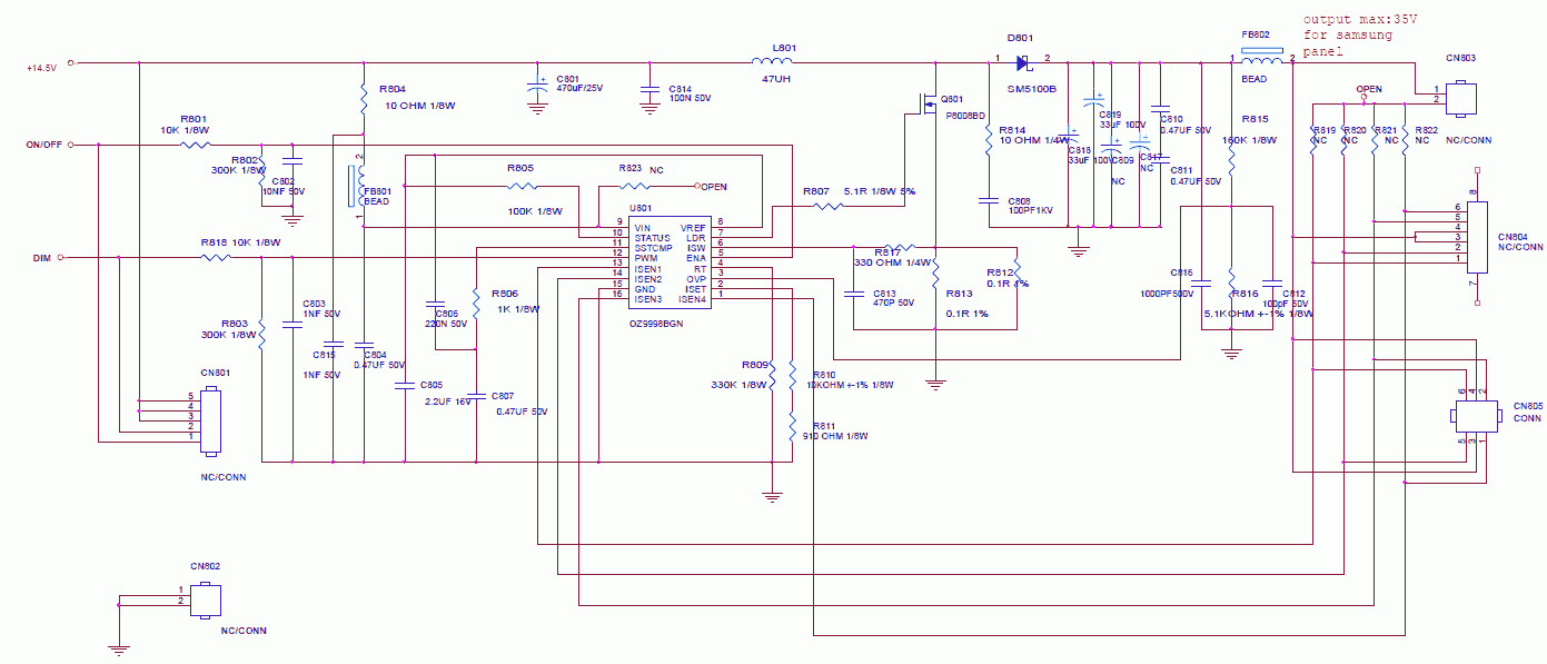
Based on the fact that all LED drivers have approximately the same structure, the analog of our OZ9998 came to hand - this is TPS61199 . Here are just the numbers of the functional conclusions of the microcircuits do not correspond to each other. After reading the documentation for TPS61199, you can determine that the output named IsetIt is responsible for setting the current value through a line of LEDs. In our OZ9998, the second leg of the chip is responsible for this functionality. The magnitude of the current linearly depends on the resistance of the resistor, multiplied by a certain coefficient (for more detailed information see TPS61199 datasheet ). Since I do not have documentation for OZ9998, I had to resort to practice. Without hesitation, he took the nearest variable resistor and soldered it in series to the existing one.
Thus, it was practically determined that the maximum installed resistance on a variable resistor at which the brightness of the backlight of the monitor is minimally acceptable for vision is 100 kOhm. By changing the value of its resistance with a potentiometer, you can change the brightness of the monitor backlight. As a result, we got a change in brightness that does not occur according to the PWM principle, but according to the principle of changing the current passing through the backlight LEDs of the LCD monitor.
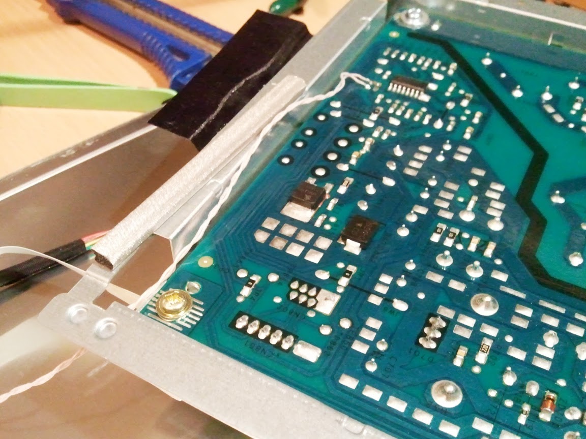
We assume that the monitor has already been disassembled (for how to disassemble the monitor, see here ):
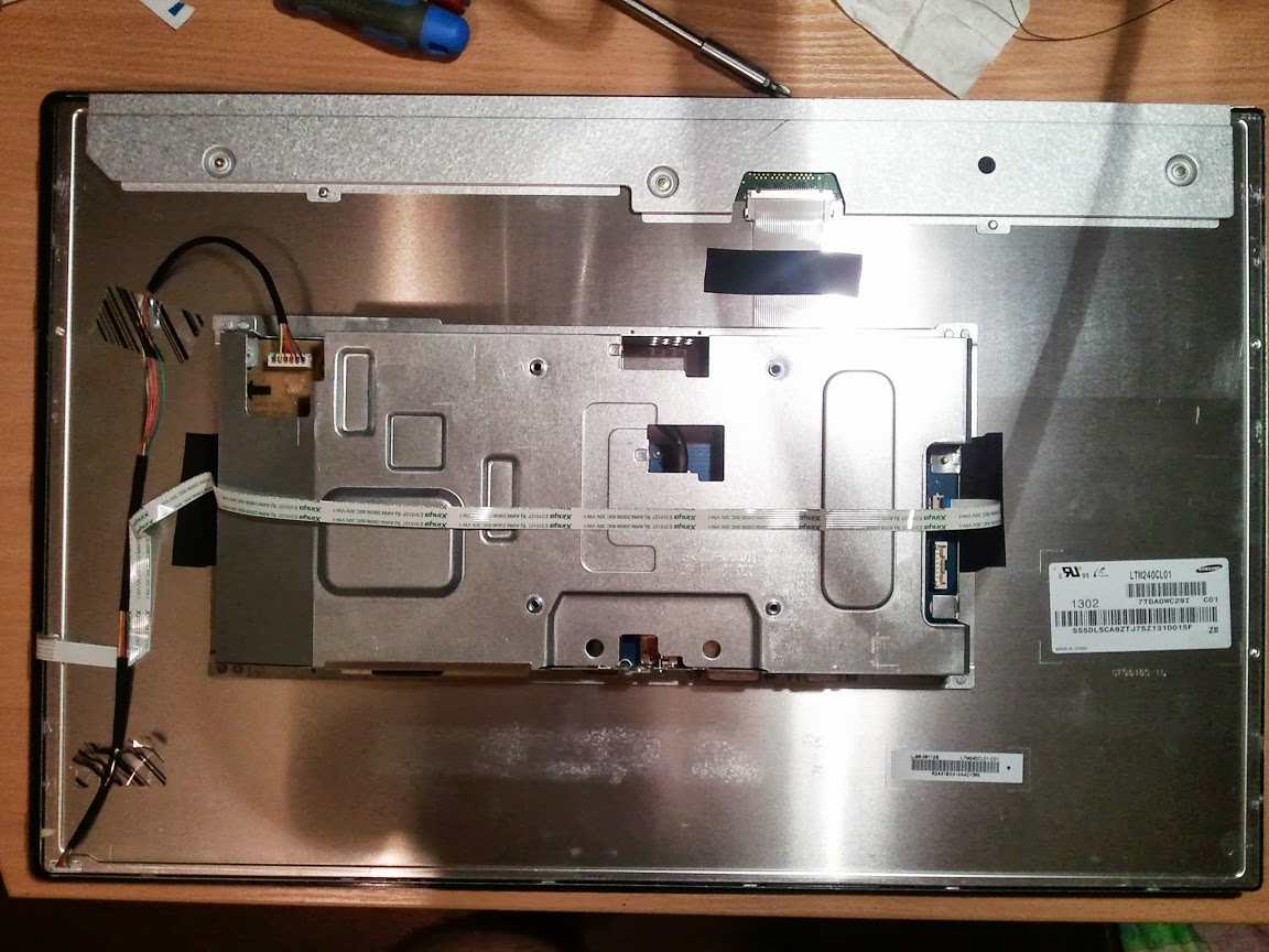
Carefully unfasten the unit with the electronics and disconnect the necessary cables:

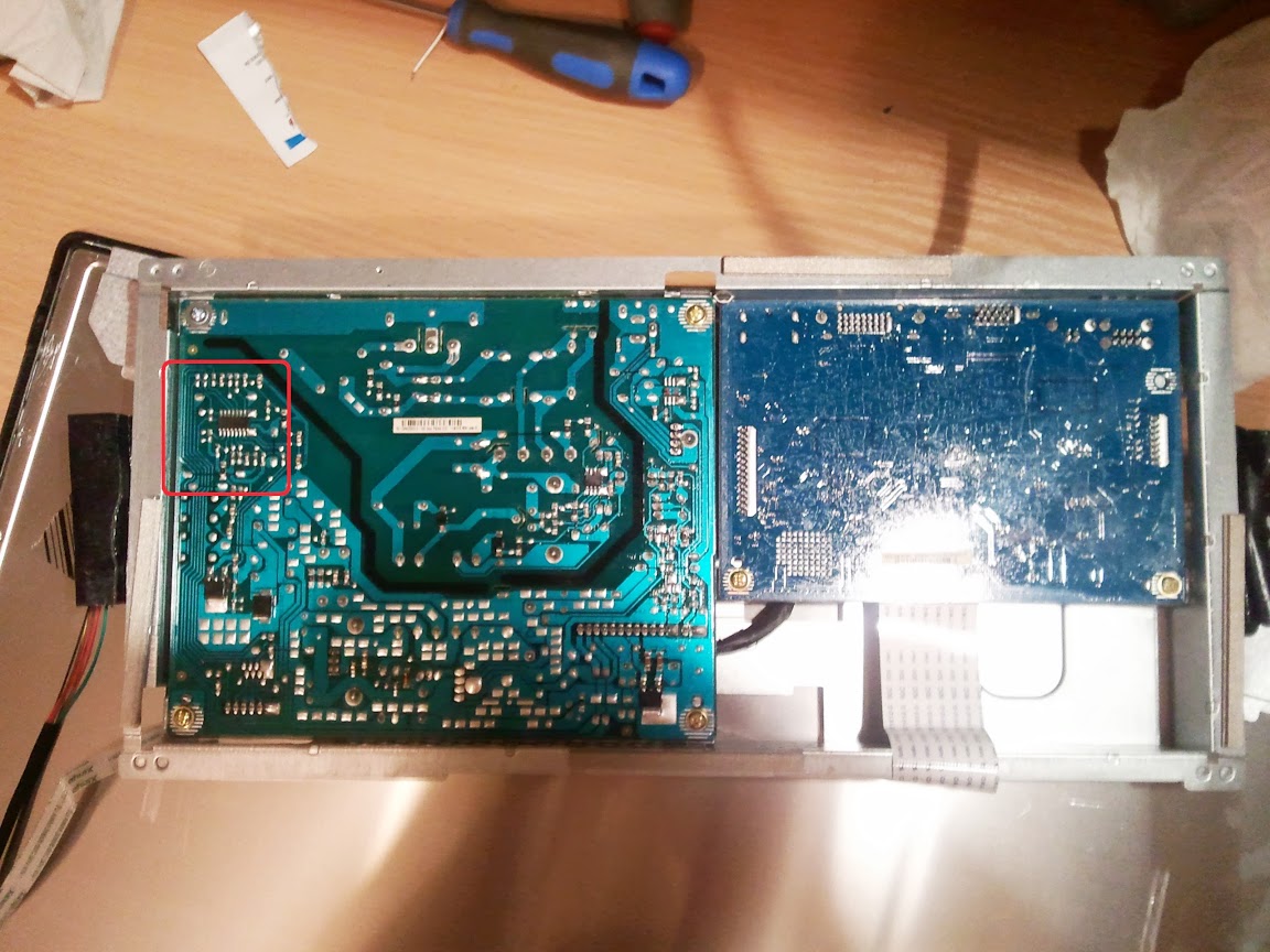
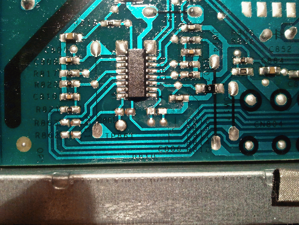
The power board together with the interface board lies before our eyes.

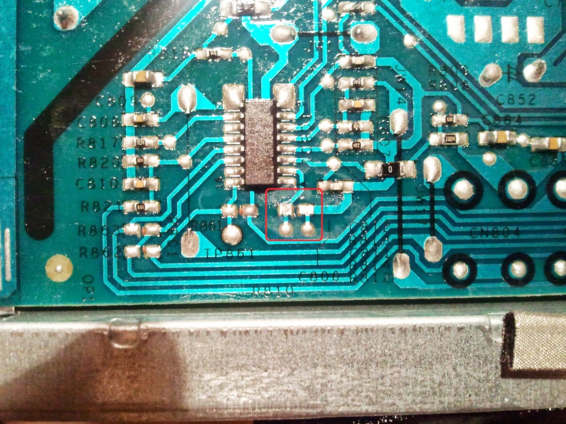
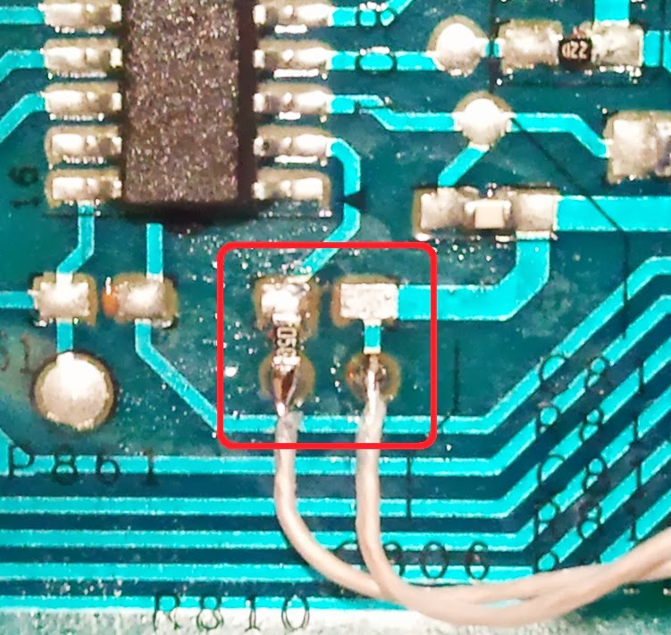
We are interested in this area:
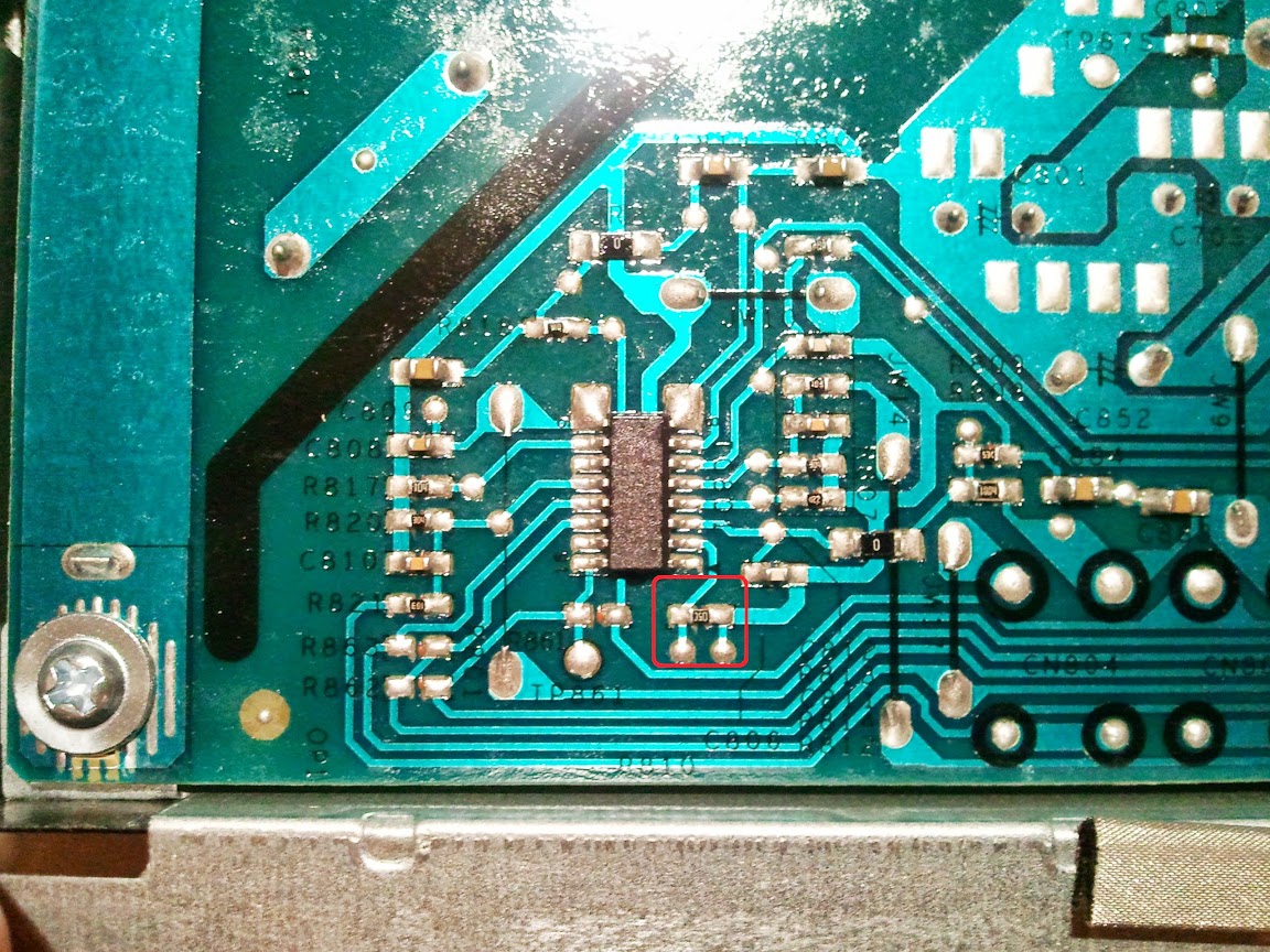
Increased:

Namely, a resistor that is connected to the second leg of the microcircuit.
In order not to accidentally exceed the current through the LEDs set by the manufacturer, we need to figure out how to solder leaving the native resistor. To do this, at the beginning we solder it.
Further affairs a small cut.
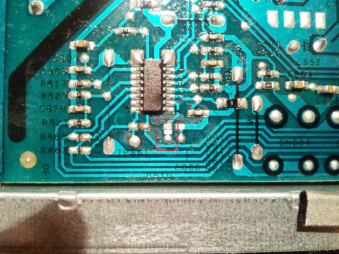
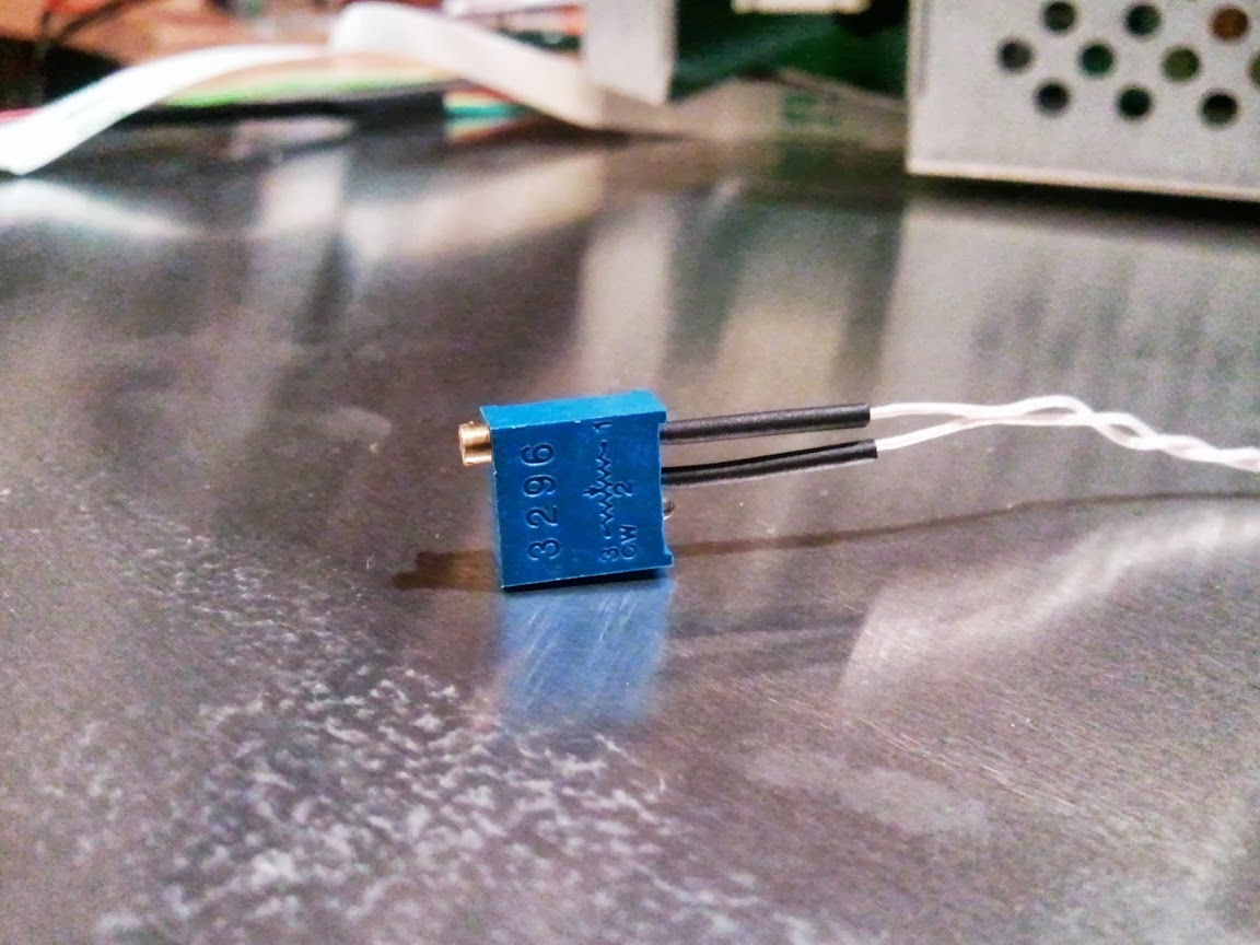
We will prepare a variable resistor, after setting the resistance between the used pins to zero.
We solder back the native resistor (the one that we pulled out) to the slot (see carefully the picture) and our variable resistor as shown in the picture, that is, sequentially.
We display a variable resistor behind the monitor body, so that it would be possible to adjust when the monitor is assembled. I did it myself like this:
That's all. Those who want to test the functionality can connect the cables and test.
The video shows how I use a variable resistor at the beginning to increase then decrease the brightness. In the second part, the brightness is changed using the internal functions of the monitor.
PS
After working behind the monitor for a while, I determined the brightness at which I am comfortable working. I measured the resistance that turned out on a variable resistor and soldered a constant resistance resistor.
Attention!
The steps in this article will void the warranty on the monitor. The author is not responsible for force majeure or other circumstances resulting in damage to your property used in attempts to repeat the steps below.
About pressing issues
Well, after much deliberation and accumulation of money, I finally became the copyright holder of a number of Dell u2412m monitors. For those who are interested, revision A0, January 2013. After reading a few forums that discuss this monitor, I came to the conclusion that many potential buyers are worried about the presence of PWM. Yes, indeed, in the first revisions, users complained about PWM, but it was clear from the reviews that in subsequent revisions this problem was fixed. Since I am not the copyright holder of the first revisions, but also the electrical circuit diagram (in order to compare the differences in electronics), from my own experience I can assume that a simple banal step was taken - increasing the frequency of the PWM.
Nevertheless, people continue to ask, asking the same question again and again - “I think I’ll take U2412M, but it’s embarrassing to have PWM. Tell me, will his eyes hurt a lot? ”
As for me, after spending a week at the monitor with the presence of PWM, getting used to it, I can say that he did not put much pressure on his eyes. Although everyone has their own body, as well as vision. Yes, in the first hours of sitting at the monitor it was unusual, but then somehow everything fell into place. Nevertheless, there were some moments that made eye strain. These moments appeared when it was required to glance from one monitor to another. It was then that I noticed PWM. Since this feeling did not give me rest, it was decided to understand the electronics of the monitor, namely the LED backlight driver.
Adding a modification, which I will discuss below, my eyes began to perceive the image on the monitor a little better ... But I can’t say that there is a big difference (or maybe I’ve just got used to it). But that's not the opinion, coming home from work, the first sensations that my eyes experience after a working monitor is rest ...
I must say right away that after making changes the user still has the opportunity to use the internal brightness change mode, which leads to the inclusion of PWM. In order for the monitor electronics not to turn on the PWM, you need to set the monitor brightness to 100% and carry out a further change in brightness using a variable resistor.
A bit about monitor electronics
(anyone who is not interested can miss it)
And so, what is the point ... But the point is that the brightness was adjusted not by the PWM principle, but by the principle of changing the current passing through the backlight LEDs of the LCD monitor. This feature is offered by most LED driver chips. But for starters, it would be nice to know what kind of chip is used to power the LED backlight in our monitor. To do this, we need to disassemble it.
I will not dwell on where and what you need to press, tighten, unwind in order to disassemble the monitor. You can easily find this information online. For example, here.
Driver IC defined - OZ9998. The next step is to find documentation for this chip. Unfortunately, my searches were unsuccessful.
Since this chip is located on the power supply board, it would be nice to find a circuit for the u2412m monitor power supply. Which was also unsuccessful. For some reason, thanks to one forum, we were able to find schemes in which our OZ9998 LED driver is used.
For example, one of the schemes:
Based on the fact that all LED drivers have approximately the same structure, the analog of our OZ9998 came to hand - this is TPS61199 . Here are just the numbers of the functional conclusions of the microcircuits do not correspond to each other. After reading the documentation for TPS61199, you can determine that the output named IsetIt is responsible for setting the current value through a line of LEDs. In our OZ9998, the second leg of the chip is responsible for this functionality. The magnitude of the current linearly depends on the resistance of the resistor, multiplied by a certain coefficient (for more detailed information see TPS61199 datasheet ). Since I do not have documentation for OZ9998, I had to resort to practice. Without hesitation, he took the nearest variable resistor and soldered it in series to the existing one.
Thus, it was practically determined that the maximum installed resistance on a variable resistor at which the brightness of the backlight of the monitor is minimally acceptable for vision is 100 kOhm. By changing the value of its resistance with a potentiometer, you can change the brightness of the monitor backlight. As a result, we got a change in brightness that does not occur according to the PWM principle, but according to the principle of changing the current passing through the backlight LEDs of the LCD monitor.
We pick up a tool and go
We assume that the monitor has already been disassembled (for how to disassemble the monitor, see here ):
Carefully unfasten the unit with the electronics and disconnect the necessary cables:
The power board together with the interface board lies before our eyes.
We are interested in this area:
Increased:
Namely, a resistor that is connected to the second leg of the microcircuit.
In order not to accidentally exceed the current through the LEDs set by the manufacturer, we need to figure out how to solder leaving the native resistor. To do this, at the beginning we solder it.
Further affairs a small cut.
We will prepare a variable resistor, after setting the resistance between the used pins to zero.
We solder back the native resistor (the one that we pulled out) to the slot (see carefully the picture) and our variable resistor as shown in the picture, that is, sequentially.
We display a variable resistor behind the monitor body, so that it would be possible to adjust when the monitor is assembled. I did it myself like this:
That's all. Those who want to test the functionality can connect the cables and test.
The video shows how I use a variable resistor at the beginning to increase then decrease the brightness. In the second part, the brightness is changed using the internal functions of the monitor.
PS
After working behind the monitor for a while, I determined the brightness at which I am comfortable working. I measured the resistance that turned out on a variable resistor and soldered a constant resistance resistor.