Large do-it-yourself portal gantry milling machine
Hello dear reader, in this article I want to share my experience in building a milling portal machine with numerical control.
There are a lot of similar stories on the web, and I’m probably wondering very few people, but maybe this article will be useful to someone. This story began at the end of 2016, when I and my friend, a partner in the development and production of test equipment, accumulated a certain amount of money. In order not to just skip the money (this is a young thing), we decided to invest it in the business, after which the idea of making a CNC machine came to mind. I already had experience in building and working with this kind of equipment, and the main area of our activity is engineering and metalworking, which was accompanied by the idea of building a CNC machine.
It was then that the movement began, which lasts to this day ...
Everything continued with the study of CNC-related forums and the choice of the basic concept of machine design. Having previously determined the materials being processed on the future machine and its working area, the first paper sketches appeared, which were later transferred to a computer. In the environment of three-dimensional modeling KOMPAS 3D, the machine was visualized and became overgrown with smaller details and nuances, which turned out to be more than we would like, some decide to this day.
One of the initial decisions was to determine the materials processed on the machine and the dimensions of the working field of the machine. As for materials, the solution was quite simple - it is wood, plastic, composite materials and non-ferrous metals (mainly duralumin). Since we have mainly metalworking machines in production, sometimes we need a machine that would process fairly simple materials in processing along a curved path, and this would later reduce the cost of production of parts ordered. Based on selected materials, mainly supplied by sheet packaging, with standard dimensions of 2.44 x1.22 meters (GOST 30427-96 for plywood). Rounding out these dimensions came to the following values: 2.5x1.5 meters, the working space is definitely, except for the height of the tool, This value was chosen because of the possibility of installing a vice and suggested that we will not have blanks thicker than 200 mm. Also take into account the time if you need to process the end of any sheet metal with a length of more than 200mm, for this tool goes beyond the dimensions of the base of the machine, and the part / workpiece is attached to the end side of the base, thereby processing the end of the part.
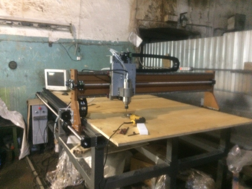
The design of the machine is a prefabricated frame base of the 80th shaped tube with a wall of 4mm. On both sides of the base are long, the fixed rolling guides of the 25th size are fixed, on which a portal is installed, made in the form of three profile pipes welded together of the same size as the base.
The machine is four axial and each axis drives a ball screw drive. Two axes are located parallel on the long side of the machine, paired software and tied to the X coordinate. Accordingly, the remaining two axes are Y and Z coordinates.
Why did they stop at the modular frame: initially they wanted to make a purely welded structure with embedded plates welded for milling, installation of ball-bearing guides and supports, but for milling they did not find a sufficiently large milling-coordinate machine. I had to draw a team frame so that I could work out all the parts on my own with the metalworking machines available for production. Every detail that was exposed to electric arc welding was annealed to relieve internal stresses. Further, all the mating surfaces were milled, and later fitting had to shabrit places.
Getting ahead, I just want to say that the assembly and manufacture of the frame turned out to be the most time-consuming and financially costly measure in the construction of the machine. The initial idea with a solidly welded frame in all respects bypasses the prefabricated structure, in our opinion. Although many may disagree with me.
Many amateurs and not only assemble machines of this kind and size (and even larger) in their workshop or garage, making an entirely welded frame, but without subsequent annealing and machining, with the exception of drilling holes for mounting the guides. Even if he was lucky with the welder, and he welded the structure with a fairly good geometry, then after the work of this machine due to bounce and vibrations, its geometry will go away, change. Of course, I can be mistaken in many ways, but if someone is aware of this issue, then please share your knowledge in the comments.
At once I want to make a reservation that we will not consider machines from an aluminum structural section here, this is rather a matter of another article.
Continuing the assembly of the machine and discussing it on the forums, many began to advise making diagonal steel braces inside and outside the frame to add even more rigidity. We didn’t neglect this advice, but add the same sticks to the construction, since the frame turned out to be quite massive (about 400 kg). And upon completion of the project, the perimeter will be treated with sheet steel, which additionally binds the structure.
Let's now move on to the mechanical issue of this project. As it was said earlier, the movement of the machine axes was carried out through a ball – screw pair with a diameter of 25 mm and a step of 10 mm, the rotation of which is transmitted from stepper motors with 86 and 57 flanges. Initially it was supposed to rotate the screw itself in order to get rid of unnecessary backlashes and additional gears, but it couldn’t have happened without them, because with a direct connection between the engine and the screw, the latter would start to unwind at high speeds, especially when the portal is in extreme positions. Considering the fact that the length of the screws along the X axis was almost three meters, and for a smaller sagging screw with a diameter of 25 mm was laid, otherwise a 16 mm screw would be enough.
This nuance was already found during the production of parts, and we had to quickly solve this problem by making a rotating nut, and not a screw, which added an additional bearing assembly and a belt drive to the design. Such a solution also allowed to tighten the screw well between the supports.
The design of the rotating nut is quite simple. Initially, we picked up two tapered ball bearings, which mirror-fit on the ball screw nut, after cutting threads from its end, to fix the bearing sleeve on the nut. Bearings together with a nut stood in the housing, in turn, the whole structure is mounted on the end of the portal gantry. In front of the screws, the nuts were fastened to the screws of the adapter sleeve, which was subsequently ground on the mandrel in order to give a connection. They put a pulley on it and tucked it in two lock nuts.
Obviously, some of you may be wondering - “Why not use a rack as a mechanism for transmitting motion?”. The answer is quite simple: the ballscrew will ensure positioning accuracy, greater driving force, and, accordingly, less torque on the motor shaft (this is what I remembered on the move). But there are also disadvantages - a lower movement speed and if we take screws of normal quality, then the price is correspondingly.
By the way, we took the screws, screws from TBI, quite a budget option, but the quality is adequate, because we had to throw 3 meters out of the 9 meters of the screw, because of the inconsistency of the geometrical sizes, none of the nuts just screwed on ...
As slide guides, rail-type rail guides of 25mm, made by HIWIN, were used. For their installation, the installation grooves were milled to maintain parallelism between the guides.
We decided to manufacture the ballscrew supports using our own resources; they turned out to be of two types: supports for rotating screws (Y and Z axes) and supports for non-rotating screws (X axis). The supports for the rotating screws could be bought, since it was not enough to save money due to the own production of 4 parts. Another thing with the supports under non-rotating screws - such supports are not on sale.
From what was said earlier, the X axis is driven by rotating nuts and through a belt gear. It was also decided to make two other axes Y and Z through the belt gear, this will add more mobility in changing the transmitted moment, add aesthetics in terms of installing the engine not along the axis of the ball screw, but on the side of it without increasing the dimensions of the machine.
Now let's move smoothly to the electrical part , and we will start with the drives, stepper motors were chosen as them, of course, for reasons of lower price as compared with motors with feedback. Two engines with 86th flange were installed on the X axis, on the Y and Z axes on the engine with the 56th flange, only with different maximum torque. Below I will try to provide a complete list of purchased parts ...
The electrical circuit of the machine is quite simple, stepper motors are connected to the drivers, they in turn are connected to the interface board, it is also connected via a parallel LPT port to a personal computer. Drivers used 4 pieces, respectively, one for each of the engines. All drivers put the same, for ease of installation and connection, with a maximum current of 4A and a voltage of 50V. As an interface board for CNC machines, I used a relatively budget option, from a domestic manufacturer, as indicated on the site is the best option. But I will not confirm or deny this, the board is simple in its application and the most important thing is that it works. In his past projects, he used boards from Chinese manufacturers, they also work, and on their periphery they differ little from the ones I used in this project. I noticed in all these boards, one may not be significant, but a minus, they can only be installed with up to 3 limit switches, but at least two such switches are required for each axis. Or I just did not understand? If we have a 3-axis machine, then accordingly we need to install limit switches in the machine’s zero coordinates (this is also called “home position”) and in the most extreme coordinates so that in the event of a malfunction or non-grip of the working field, one or another axis out of order (simply did not break). In my scheme used: 3 end without contact inductive sensors and emergency button "E-STOP" in the form of a fungus. The power unit is powered by two 48V switching power supplies. and 8A. Water-cooled spindle to 2.2kW, respectively included through the frequency converter. Turns are set from a personal computer, since the frequency converter is connected via an interface card. Turns are adjusted with a voltage change (0-10 volts) at the appropriate output of the frequency converter.
All electrical components, except motors, spindle and limit switches were mounted in an electrical metal cabinet. All control of the machine is made from a personal computer, we found an old PC on the motherboard form ATX. It would have been better if we got a little shorter and bought a small mini-ITX with a built-in processor and a video card. With not small dimensions of the electric box, all the components hardly settled inside, they had to be located close enough to each other. In the bottom of the box placed three forced cooling fans, as the air inside the box was very hot. From the front side of the metal plate fastened with holes for the power button and emergency stop button. Also on this pad was placed the panel to turn on the PC, I took it off the case of the old mini computer, pity that he was not working. From the back end of the box, they also secured the cover, and placed holes in it for connectors for connecting 220V power, stepping motors, spindle and VGA connector.
All wires from the engines, the spindle, and also the water hoses for its cooling, laid in flexible cable channels of the caterpillar type, 50 mm wide.
As for the software, they installed Windows XP on a PC located in an electric box and used one of the most popular Mach3 programs to control the machine. Program setting is carried out in accordance with the documentation on the interface board, everything is described quite clearly in the pictures. Why Mach3, yes, all for the same, was the experience, I heard about other programs, but did not consider them.
Specifications:
Workspace, mm: 2700x1670x200;
The speed of movement of the axes, mm / min: 3000;
Spindle power, kW: 2.2;
Dimensions, mm: 2800x2070x1570;
Weight, kg: 1430.
List of parts:
Profile pipe 80x80 mm.
Metal strip 10x80mm.
Ball screw TBI 2510, 9 meters.
Ball screws nut TBI 2510, 4 pcs.
Profile guides HIWIN carriage HGH25-CA, 12 pcs.
Rail HGH25, 10 meters.
Stepper motors:
NEMA34-8801: 3 pcs.
NEMA 23_2430: 1pc.
Pulley BLA-25-5M-15-A-N14: 4 pcs.
Pulley BLA-40-T5-20-AN 19: 2 pcs.
Pulley BLA-30-T5-20-A-N14: 2 pcs.
Interface Board StepMaster v2.5: 1 pcs.
DM542 stepper motor driver: 4pcs. (China)
Switching power supply 48V, 8A: 2 pcs. (China)
2.2 kW frequency converter. (China)
2.2 kW spindle. (China)
The main parts and components like listed, if something is not included, then write in the comments, add.
Experience in the machine: In the end, after almost a year and a half, we still started the machine. First, we adjust the positioning accuracy of the axes and their maximum speed. According to more experienced colleagues, the maximum speed of 3 m / min is not high and should be three times higher (for processing wood, plywood, etc.). At that speed, which we have reached, the portal and other axes resting in them with their hands (with their whole body) can hardly be stopped - rushing like a tank. Began testing with the processing of plywood, the cutter goes like clockwork, the machine does not vibrate, but it deepened to a maximum of 10 mm in one pass. Although after deepening began to shallower.
Having played with wood and plastic, we decided to gnaw duralumin, here I was delighted, although at first I broke several cutters with a diameter of 2 mm while I selected cutting modes. Dural cuts very confidently, and a fairly clean cut is obtained along the treated edge.
We have not tried to process the steel yet, but I think that at least the machine will pull up the engraving, and the spindle is weak for milling, it’s a pity to kill him.
And the rest of the machine perfectly copes with its tasks.
Conclusion, opinion on the work done: The work was done is not small, we ended up pretty hard, because no one has canceled the main work. Yes, and the money invested is not enough, I will not say the exact amount, but this is about 400t.r. In addition to the cost of equipment, the bulk of the costs and most of the forces went to the manufacture of the base. Wow, how are we with him. For the rest, everything was done as funds, time and finished parts were received to continue the assembly.
The machine turned out to be quite efficient, quite tough, massive and high-quality. Maintains good positioning accuracy. When measuring a square of duralumin, size 40x40, the accuracy was + + - 0.05 mm. Accuracy of processing more dimensional parts is not measured.
What's next…:On the machine there is still enough work in the form of closing the dust - protecting the guides and ball screws, covering the machine around the perimeter and installing overlaps in the middle of the base, which will form 4 large shelves, under the volume of spindle cooling, tool storage and tooling. One of the quarters of the base would be equipped with a fourth axis. It is also required to install a cyclone on the spindle to remove and collect chips about dust, especially if you process wood or PCB, dust flies from them everywhere and is deposited everywhere.
As for the further fate of the machine, then everything is not straightforward, since I had a territorial question (I moved to another city), and now there is almost no one to deal with the machine. And the above plans are not the fact that they will come true. Not who this two years ago and could not imagine.
In the case of the sale of the machine with its price tag, everything is not clear. Since it is frankly pitiful to sell at cost, but an adequate price does not come to mind.
On this, I probably finish my story. If I did not light something, then write to me, and I will try to add text. For the rest, much is shown in the video about the production of the machine on my YouTube channel.
There are a lot of similar stories on the web, and I’m probably wondering very few people, but maybe this article will be useful to someone. This story began at the end of 2016, when I and my friend, a partner in the development and production of test equipment, accumulated a certain amount of money. In order not to just skip the money (this is a young thing), we decided to invest it in the business, after which the idea of making a CNC machine came to mind. I already had experience in building and working with this kind of equipment, and the main area of our activity is engineering and metalworking, which was accompanied by the idea of building a CNC machine.
It was then that the movement began, which lasts to this day ...
Everything continued with the study of CNC-related forums and the choice of the basic concept of machine design. Having previously determined the materials being processed on the future machine and its working area, the first paper sketches appeared, which were later transferred to a computer. In the environment of three-dimensional modeling KOMPAS 3D, the machine was visualized and became overgrown with smaller details and nuances, which turned out to be more than we would like, some decide to this day.
One of the initial decisions was to determine the materials processed on the machine and the dimensions of the working field of the machine. As for materials, the solution was quite simple - it is wood, plastic, composite materials and non-ferrous metals (mainly duralumin). Since we have mainly metalworking machines in production, sometimes we need a machine that would process fairly simple materials in processing along a curved path, and this would later reduce the cost of production of parts ordered. Based on selected materials, mainly supplied by sheet packaging, with standard dimensions of 2.44 x1.22 meters (GOST 30427-96 for plywood). Rounding out these dimensions came to the following values: 2.5x1.5 meters, the working space is definitely, except for the height of the tool, This value was chosen because of the possibility of installing a vice and suggested that we will not have blanks thicker than 200 mm. Also take into account the time if you need to process the end of any sheet metal with a length of more than 200mm, for this tool goes beyond the dimensions of the base of the machine, and the part / workpiece is attached to the end side of the base, thereby processing the end of the part.
The design of the machine is a prefabricated frame base of the 80th shaped tube with a wall of 4mm. On both sides of the base are long, the fixed rolling guides of the 25th size are fixed, on which a portal is installed, made in the form of three profile pipes welded together of the same size as the base.
The machine is four axial and each axis drives a ball screw drive. Two axes are located parallel on the long side of the machine, paired software and tied to the X coordinate. Accordingly, the remaining two axes are Y and Z coordinates.
Why did they stop at the modular frame: initially they wanted to make a purely welded structure with embedded plates welded for milling, installation of ball-bearing guides and supports, but for milling they did not find a sufficiently large milling-coordinate machine. I had to draw a team frame so that I could work out all the parts on my own with the metalworking machines available for production. Every detail that was exposed to electric arc welding was annealed to relieve internal stresses. Further, all the mating surfaces were milled, and later fitting had to shabrit places.
Getting ahead, I just want to say that the assembly and manufacture of the frame turned out to be the most time-consuming and financially costly measure in the construction of the machine. The initial idea with a solidly welded frame in all respects bypasses the prefabricated structure, in our opinion. Although many may disagree with me.
Many amateurs and not only assemble machines of this kind and size (and even larger) in their workshop or garage, making an entirely welded frame, but without subsequent annealing and machining, with the exception of drilling holes for mounting the guides. Even if he was lucky with the welder, and he welded the structure with a fairly good geometry, then after the work of this machine due to bounce and vibrations, its geometry will go away, change. Of course, I can be mistaken in many ways, but if someone is aware of this issue, then please share your knowledge in the comments.
At once I want to make a reservation that we will not consider machines from an aluminum structural section here, this is rather a matter of another article.
Continuing the assembly of the machine and discussing it on the forums, many began to advise making diagonal steel braces inside and outside the frame to add even more rigidity. We didn’t neglect this advice, but add the same sticks to the construction, since the frame turned out to be quite massive (about 400 kg). And upon completion of the project, the perimeter will be treated with sheet steel, which additionally binds the structure.
Let's now move on to the mechanical issue of this project. As it was said earlier, the movement of the machine axes was carried out through a ball – screw pair with a diameter of 25 mm and a step of 10 mm, the rotation of which is transmitted from stepper motors with 86 and 57 flanges. Initially it was supposed to rotate the screw itself in order to get rid of unnecessary backlashes and additional gears, but it couldn’t have happened without them, because with a direct connection between the engine and the screw, the latter would start to unwind at high speeds, especially when the portal is in extreme positions. Considering the fact that the length of the screws along the X axis was almost three meters, and for a smaller sagging screw with a diameter of 25 mm was laid, otherwise a 16 mm screw would be enough.
This nuance was already found during the production of parts, and we had to quickly solve this problem by making a rotating nut, and not a screw, which added an additional bearing assembly and a belt drive to the design. Such a solution also allowed to tighten the screw well between the supports.
The design of the rotating nut is quite simple. Initially, we picked up two tapered ball bearings, which mirror-fit on the ball screw nut, after cutting threads from its end, to fix the bearing sleeve on the nut. Bearings together with a nut stood in the housing, in turn, the whole structure is mounted on the end of the portal gantry. In front of the screws, the nuts were fastened to the screws of the adapter sleeve, which was subsequently ground on the mandrel in order to give a connection. They put a pulley on it and tucked it in two lock nuts.
Obviously, some of you may be wondering - “Why not use a rack as a mechanism for transmitting motion?”. The answer is quite simple: the ballscrew will ensure positioning accuracy, greater driving force, and, accordingly, less torque on the motor shaft (this is what I remembered on the move). But there are also disadvantages - a lower movement speed and if we take screws of normal quality, then the price is correspondingly.
By the way, we took the screws, screws from TBI, quite a budget option, but the quality is adequate, because we had to throw 3 meters out of the 9 meters of the screw, because of the inconsistency of the geometrical sizes, none of the nuts just screwed on ...
As slide guides, rail-type rail guides of 25mm, made by HIWIN, were used. For their installation, the installation grooves were milled to maintain parallelism between the guides.
We decided to manufacture the ballscrew supports using our own resources; they turned out to be of two types: supports for rotating screws (Y and Z axes) and supports for non-rotating screws (X axis). The supports for the rotating screws could be bought, since it was not enough to save money due to the own production of 4 parts. Another thing with the supports under non-rotating screws - such supports are not on sale.
From what was said earlier, the X axis is driven by rotating nuts and through a belt gear. It was also decided to make two other axes Y and Z through the belt gear, this will add more mobility in changing the transmitted moment, add aesthetics in terms of installing the engine not along the axis of the ball screw, but on the side of it without increasing the dimensions of the machine.
Now let's move smoothly to the electrical part , and we will start with the drives, stepper motors were chosen as them, of course, for reasons of lower price as compared with motors with feedback. Two engines with 86th flange were installed on the X axis, on the Y and Z axes on the engine with the 56th flange, only with different maximum torque. Below I will try to provide a complete list of purchased parts ...
The electrical circuit of the machine is quite simple, stepper motors are connected to the drivers, they in turn are connected to the interface board, it is also connected via a parallel LPT port to a personal computer. Drivers used 4 pieces, respectively, one for each of the engines. All drivers put the same, for ease of installation and connection, with a maximum current of 4A and a voltage of 50V. As an interface board for CNC machines, I used a relatively budget option, from a domestic manufacturer, as indicated on the site is the best option. But I will not confirm or deny this, the board is simple in its application and the most important thing is that it works. In his past projects, he used boards from Chinese manufacturers, they also work, and on their periphery they differ little from the ones I used in this project. I noticed in all these boards, one may not be significant, but a minus, they can only be installed with up to 3 limit switches, but at least two such switches are required for each axis. Or I just did not understand? If we have a 3-axis machine, then accordingly we need to install limit switches in the machine’s zero coordinates (this is also called “home position”) and in the most extreme coordinates so that in the event of a malfunction or non-grip of the working field, one or another axis out of order (simply did not break). In my scheme used: 3 end without contact inductive sensors and emergency button "E-STOP" in the form of a fungus. The power unit is powered by two 48V switching power supplies. and 8A. Water-cooled spindle to 2.2kW, respectively included through the frequency converter. Turns are set from a personal computer, since the frequency converter is connected via an interface card. Turns are adjusted with a voltage change (0-10 volts) at the appropriate output of the frequency converter.
All electrical components, except motors, spindle and limit switches were mounted in an electrical metal cabinet. All control of the machine is made from a personal computer, we found an old PC on the motherboard form ATX. It would have been better if we got a little shorter and bought a small mini-ITX with a built-in processor and a video card. With not small dimensions of the electric box, all the components hardly settled inside, they had to be located close enough to each other. In the bottom of the box placed three forced cooling fans, as the air inside the box was very hot. From the front side of the metal plate fastened with holes for the power button and emergency stop button. Also on this pad was placed the panel to turn on the PC, I took it off the case of the old mini computer, pity that he was not working. From the back end of the box, they also secured the cover, and placed holes in it for connectors for connecting 220V power, stepping motors, spindle and VGA connector.
All wires from the engines, the spindle, and also the water hoses for its cooling, laid in flexible cable channels of the caterpillar type, 50 mm wide.
As for the software, they installed Windows XP on a PC located in an electric box and used one of the most popular Mach3 programs to control the machine. Program setting is carried out in accordance with the documentation on the interface board, everything is described quite clearly in the pictures. Why Mach3, yes, all for the same, was the experience, I heard about other programs, but did not consider them.
Specifications:
Workspace, mm: 2700x1670x200;
The speed of movement of the axes, mm / min: 3000;
Spindle power, kW: 2.2;
Dimensions, mm: 2800x2070x1570;
Weight, kg: 1430.
List of parts:
Profile pipe 80x80 mm.
Metal strip 10x80mm.
Ball screw TBI 2510, 9 meters.
Ball screws nut TBI 2510, 4 pcs.
Profile guides HIWIN carriage HGH25-CA, 12 pcs.
Rail HGH25, 10 meters.
Stepper motors:
NEMA34-8801: 3 pcs.
NEMA 23_2430: 1pc.
Pulley BLA-25-5M-15-A-N14: 4 pcs.
Pulley BLA-40-T5-20-AN 19: 2 pcs.
Pulley BLA-30-T5-20-A-N14: 2 pcs.
Interface Board StepMaster v2.5: 1 pcs.
DM542 stepper motor driver: 4pcs. (China)
Switching power supply 48V, 8A: 2 pcs. (China)
2.2 kW frequency converter. (China)
2.2 kW spindle. (China)
The main parts and components like listed, if something is not included, then write in the comments, add.
Experience in the machine: In the end, after almost a year and a half, we still started the machine. First, we adjust the positioning accuracy of the axes and their maximum speed. According to more experienced colleagues, the maximum speed of 3 m / min is not high and should be three times higher (for processing wood, plywood, etc.). At that speed, which we have reached, the portal and other axes resting in them with their hands (with their whole body) can hardly be stopped - rushing like a tank. Began testing with the processing of plywood, the cutter goes like clockwork, the machine does not vibrate, but it deepened to a maximum of 10 mm in one pass. Although after deepening began to shallower.
Having played with wood and plastic, we decided to gnaw duralumin, here I was delighted, although at first I broke several cutters with a diameter of 2 mm while I selected cutting modes. Dural cuts very confidently, and a fairly clean cut is obtained along the treated edge.
We have not tried to process the steel yet, but I think that at least the machine will pull up the engraving, and the spindle is weak for milling, it’s a pity to kill him.
And the rest of the machine perfectly copes with its tasks.
Conclusion, opinion on the work done: The work was done is not small, we ended up pretty hard, because no one has canceled the main work. Yes, and the money invested is not enough, I will not say the exact amount, but this is about 400t.r. In addition to the cost of equipment, the bulk of the costs and most of the forces went to the manufacture of the base. Wow, how are we with him. For the rest, everything was done as funds, time and finished parts were received to continue the assembly.
The machine turned out to be quite efficient, quite tough, massive and high-quality. Maintains good positioning accuracy. When measuring a square of duralumin, size 40x40, the accuracy was + + - 0.05 mm. Accuracy of processing more dimensional parts is not measured.
What's next…:On the machine there is still enough work in the form of closing the dust - protecting the guides and ball screws, covering the machine around the perimeter and installing overlaps in the middle of the base, which will form 4 large shelves, under the volume of spindle cooling, tool storage and tooling. One of the quarters of the base would be equipped with a fourth axis. It is also required to install a cyclone on the spindle to remove and collect chips about dust, especially if you process wood or PCB, dust flies from them everywhere and is deposited everywhere.
As for the further fate of the machine, then everything is not straightforward, since I had a territorial question (I moved to another city), and now there is almost no one to deal with the machine. And the above plans are not the fact that they will come true. Not who this two years ago and could not imagine.
In the case of the sale of the machine with its price tag, everything is not clear. Since it is frankly pitiful to sell at cost, but an adequate price does not come to mind.
On this, I probably finish my story. If I did not light something, then write to me, and I will try to add text. For the rest, much is shown in the video about the production of the machine on my YouTube channel.