FIFO UART buffer features in ESP32
ESP32 has three UARTs. Each of which places the FIFO buffer of the receiver and the FIFO buffer of the transmitter in shared memory of 1024 bytes (ESP32 technical reference manual 3.5):
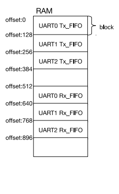
However, when trying to increase the size of the FIFO buffer of the UART2 transmitter from 128 to 256 bytes, it had an unexpected effect - the transmitted data spoiled the FIFO buffer of the UART0 receiver, which according to the documentation should not be.
Unfortunately, the documentation (ESP32 technical reference manual 3.5) does not contain a description of the FIFO buffer registers. However, in the header files esp-idf (in uart_struct.h) showed up:
1) FIFO transmitter buffer status register (offset from base address 0x5c):
union {
        struct {uint32_t status:24;
            uint32_t reserved24:    8;
        };
        uint32_t val;
    } mem_tx_status;
2) FIFO status register of the receiver buffer (offset relative to the base address 0x60):
union {
        struct {uint32_t status:      24;
            uint32_t reserved24:   8;
        };
        struct {uint32_t reserved0:     2;
            uint32_t rd_addr:      11;              /*This register stores the rx mem read address.*/uint32_t wr_addr:      11;              /*This register stores the rx mem write address.*/uint32_t reserved:      8;
        };
        uint32_t val;
    } mem_rx_status;
Assuming that mem_tx_status corresponds in purpose to the mem_rx_status bit, we write the following code to get the FIFO addresses of the buffers:
#include"freertos/FreeRTOS.h"#include"freertos/task.h"#include<driver/uart.h>voidprint_uart_st(uart_dev_t *u,int num){
    printf("UART%d:\n",num);
    printf("rx_st=0x%X\n",(unsignedint)u->mem_rx_status.val);
    printf("rx_rd=0x%X\n",(unsignedint)u->mem_rx_status.rd_addr);
    printf("rx_wr=0x%X\n",(unsignedint)u->mem_rx_status.wr_addr);
    uint32_t tx_s = u->mem_tx_status.val;
    printf("tx_st=0x%X\n",tx_s);
    printf("tx_rd=0x%X\n",(tx_s>>2)&2047);
    printf("tx_wr=0x%X\n",(tx_s>>13)&2047);
}
uart_config_t uart_config =
{
    .baud_rate = 115200,
    .data_bits = UART_DATA_8_BITS,
    .parity    = UART_PARITY_DISABLE,
    .stop_bits = UART_STOP_BITS_1,
    .flow_ctrl = UART_HW_FLOWCTRL_DISABLE
};
voidUARTtest(void * param){
    uart_param_config(UART_NUM_1,&uart_config);
    uart_param_config(UART_NUM_2,&uart_config);
    uart_driver_install(UART_NUM_1, 256, 0, 0, NULL, 0);
    uart_driver_install(UART_NUM_2, 256, 0, 0, NULL, 0);
    uart_set_pin(UART_NUM_1, UART_PIN_NO_CHANGE, GPIO_NUM_16, UART_PIN_NO_CHANGE, UART_PIN_NO_CHANGE);
    uart_set_pin(UART_NUM_2, UART_PIN_NO_CHANGE, GPIO_NUM_16, UART_PIN_NO_CHANGE, UART_PIN_NO_CHANGE);
    vTaskDelay(1000/portTICK_PERIOD_MS);
    while (1)
    {
        print_uart_st(&UART0,0);
        print_uart_st(&UART1,1);
        print_uart_st(&UART2,2);
        vTaskDelay(2000/portTICK_PERIOD_MS);
        char s[256];
        uart_write_bytes(UART_NUM_1, s, 1);
        uart_write_bytes(UART_NUM_2, s, 2);
        if(gets(s)!=NULL)
        {
            printf("recived=%s\n",s);
        }
    }
}
voidapp_main(void){
    xTaskCreate(UARTtest, "UARTtest",    4096, NULL, 5, NULL);
}
After launch we get:
To UART0 of:
rx_st = 0x300600
rx_rd = 0x180
rx_wr = 0x180
tx_st = 0xCE058
tx_rd = 0x16
tx_wr = 0x67
UART1:
rx_st = 0x400800
rx_rd = 0x200
rx_wr = 0x200
tx_st = 0x100200
tx_rd = 0x80
tx_wr = 0x80
UART2:
rx_st = 0x500A00
rx_rd = 0x280
rx_wr = 0x280
tx_st = 0x200400
tx_rd = 0x100
tx_wr = 0x100
Output is via UART0, so tx_wr and tx_rd are different from 0. According to the results, the memory allocation between the FIFO UART0,1,2 buffers is as follows:
| Addresses | UART |
|---|---|
| 0x00 ... 0x7F | UART0 TX_FIFO |
| 0x80 ... 0xFF | UART1 TX_FIFO |
| 0x100 ... 0x17F | UART2 TX_FIFO |
| 0x180 ... 0x1FF | UART0 RX_FIFO |
| 0x200 ... 0x27F | UART1 RX_FIFO |
| 0x280 ... 0x2FF | UART2 RX_FIFO |
In addition, the status registers of the FIFO buffers are 11 bits wide, which means that the memory size allocated for the FIFO buffer = 2Kb is possible. When setting UART0.mem_conf.tx_size = 15 (memory is allocated chunks of 128 bytes), 1920 bytes will be allocated, and the tx_wr register will transmit to 1919 during transmission and then go through 0 to continue counting. However, the memory is addressed only ml. 10 bits, i.e. real total memory allocated for FIFO buffer = 1Kb.
Total:
- The distribution of the total memory allocated by ESP32 to the FIFO UART does not match that given in the technical reference manual 3.5;
- Total memory FIFO UART = 1Kb.