Lun hovercraft Part 2
Good day!
As promised, I will continue my previous post with a more detailed description of the electronic filling and software.
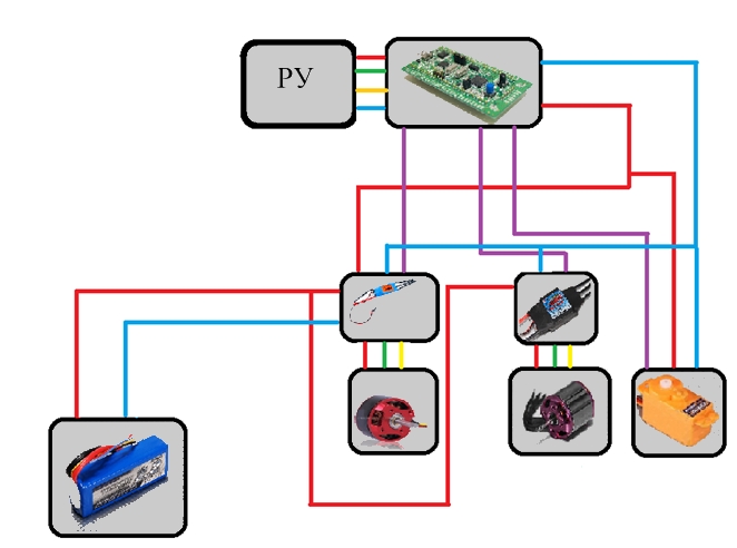
The first design option was very simple: stm32vl-discovery, a remote control from an ancient radio-controlled machine and 2 inverters for motors. If it looked schematically, it looked something like this:
In the firmware as well as in the layout, there was nothing complicated either. Everything was controlled by stm32vl-discovery, and the code was written in a couple of hours in CoIDE. I would also like to express a low bow to the developers of this programming environment, if it weren’t for its convenience, whoever knows, maybe I would not have climbed with AVR.
The management implementation was simple but completely inconvenient. In SVP, it was necessary to control three engines, and the console made it possible to control only two. I had to somehow get out, the “forward” button controlled the traction screw, the “back” button stopped the vessel, and the vessel was launched by pressing the button on the debug board itself.
Having set up a mountain of crutches both in the program and in the mechanical part of our robot, we decided that we had to completely redo everything.
The first thing they decided to add stability and ease of management. For this, the MPU-6050 sensor and the bluetooth HC-04 module were purchased.
There were no problems with bluetooth, but for some reason the accelerometer did not work correctly. First, after 10 seconds of operation, he turned off, and then completely stopped responding.
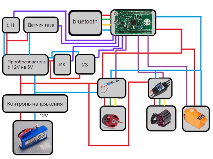
After thinking about the possible options, it was decided to replace the debug board, and with it the whole layout scheme.
This is what happened:
The main disappointment was to find out that CoIDE does not support programming of STM32F303 microcontrollers. Without hesitation, a commercial assembly of the same eclipse - Atollic TrueSTUDIO was installed. The lite version was limited by the size of the compiled firmware (no more than 32KB), it suited us and the project moved to another environment.
On the ST site you can download the source code of examples for this IDE, which also made us happy. Problems appeared when they began to study the code in depth. The fact is that you simply cannot copy the code from the previous firmware; in STM32f3, in comparison with STM32f100, the purpose of many registers has changed. And at that time we found only examples from the manufacturer, it felt like no one was doing this debugging board at all, although it had been on sale for a year now. Problems were added when we decided to install a humidity sensor. I honestly borrowed the code for working with the sensor from the article ”STM32 + DHT11”, but the firmware written up to this point completely refused to work with the new code, it simply did not execute. There were no errors or warnings during compilation, but the code stubbornly did not want to execute correctly, killing two days and a lot of nerve cells revealed that if you disable optimization in the settings, everything would work. But then there was a problem that I did not expect at all, after disabling optimization, the firmware size began to exceed 32K, I had to look for a new development environment. After some time searching, I came across an article about setting up an Eclipse-based IDE. It remains to create a project and move again.
Along with the purchase of the bluetooth module, the development of an application for android began. Before that, I had never written an application for mobile devices, so it was quite difficult to start. The misunderstanding of how the button moved in the graphical editor caused an error and the application was closing me down was especially crazy.
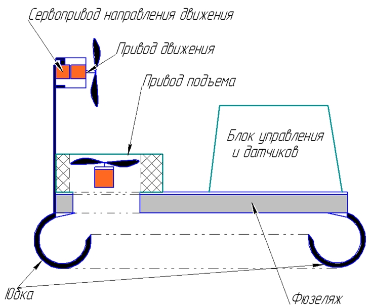
In addition to programmatic changes, a lot of time was devoted to the layout processing.

The fuselage, skirt and mast with a guiding engine left from the first version. The engine was installed in a vertical position, and the electronics were moved to one place. Also, for the convenience of connecting peripherals, a patch board was
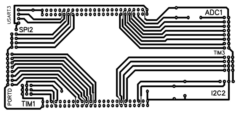
bred: I don’t see the point in the article in the article, I think it would be better if I pay more attention to the points that caused the problems.
What tasks were set for the program:
0. To control servos and inverters;
1. Read data from sensors built into the debug board;
2. According to the indications, adjust the course;
3. Receive and send data to the phone;
4. Stop or go around obstacles in the way;
5. Search for a suitable route;
6. Read data from peripheral sensors;
7. Do not let the battery run out too much.
Point zero was organized on PWM with three channels. As a result, after executing the code, the following picture should have been obtained:
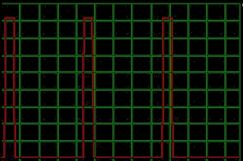
where vertically one cell is 0.4 volts, and horizontally one cell is 2.5 ms.
To change the speed it was only necessary to write:
The first point was completely decided by examples from the manufacturer. Yes, I could take the data, but without processing it was difficult to do something.
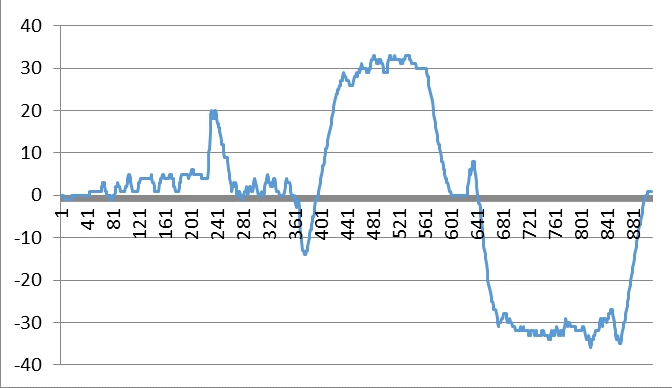
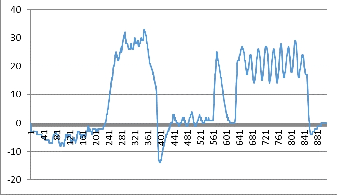
Graphs display accelerometer readings without filters. First there is a roll, then pitch, then at the same time both roll and pitch.
Therefore, it was already more difficult with the second one, if the source codes for position correction for one sensor in the network were still present, so that the correction took into account all three sensors had to be searched. After several days of reading Wikipedia ( AHRS , IMU , Quaternion , Euler Corners , Kalman Filter ), googling and viewing source codes, reading articles and forums, Rudolph Emil Kalman himself appeared to me in a dream and dictated a link toA British company that did basically the same thing as me. It was with them that I spied an open library for processing data from sensors. There they also have a small description and method of application. From it I took formulas for calculating from quaternions of roll, pitch and yaw.
When the SVP enters the course correction mode, the current position is taken as a reference point:
Next, the current position is determined in the same way and the angle between the reference point and the current position is calculated.
After calculating the angle, the data is transmitted to the servo drive where the correction angle is subtracted from the current rotation angle.
There were no problems with the third paragraph, it is not difficult to find examples of working with UART or with HC-04.
With the fourth point there were some troubles, the ultrasonic sensor arrived at the same time as the humidity sensor, and I was looking for a new development environment. Yes, and testing the sensor destroyed my pink dreams that it hits in a straight narrow beam and is reflected back regardless of the material and the angle of rotation of the surface. In order not to load MK with unnecessary tasks, communication with the sensor is organized on interrupts. An example is taken from this good man in this place . I had to redo the code a bit, as the timers changed the STM32f3 a bit.
This code uses an interrupt on PORTD.3, or rather it should be on PORTD, I still have not figured out why the interrupt is triggered on all ports on the third pin. The use of an interrupt is taken from an example from the manufacturer, an attempt was made to write directly to the interrupt setup registers, the result is “0” or there is no interrupt, or it is on all ports.
If someone explains where the error will be very grateful.
The fifth point was quickly passed, but the tuning of the ADC in the sixth caused some headache.
Again, examples, no complaints, the example works fine. Only in the example they considered reading from one ADC channel, and I have four of them. The datasheet signs about the channels, regular groups, entered groups. Due to the limited time, the old "grandfather" method was chosen:
-Choice of the channel;
-Start one-time reading;
-Processing the result;
-Repeat.
After I figured out the ADC, the seventh paragraph did not cause problems.
The application for android did not cause any special difficulties and losses on the part of nerve cells (apart from departures from changing the location of the button) there are plenty of examples for working with bluetooth on the network, and a slightly modified class from this article added the ability to control the speed and direction of the vessel by moving the finger up / down and left / right on the screen.
And to display information about the sensors, DialogFragment was used:
I know that the creation process has covered only in general terms, but if there are questions, I will definitely try to answer them. The management program is far from ideal, there is still a lot to consider. For example, with a sharp turn, the inertia of the ship makes it “wag its tail” for another seven meters. But we will continue and improve our work.
As promised, I will continue my previous post with a more detailed description of the electronic filling and software.
Lun 1.0
The first design option was very simple: stm32vl-discovery, a remote control from an ancient radio-controlled machine and 2 inverters for motors. If it looked schematically, it looked something like this:
In the firmware as well as in the layout, there was nothing complicated either. Everything was controlled by stm32vl-discovery, and the code was written in a couple of hours in CoIDE. I would also like to express a low bow to the developers of this programming environment, if it weren’t for its convenience, whoever knows, maybe I would not have climbed with AVR.
The management implementation was simple but completely inconvenient. In SVP, it was necessary to control three engines, and the console made it possible to control only two. I had to somehow get out, the “forward” button controlled the traction screw, the “back” button stopped the vessel, and the vessel was launched by pressing the button on the debug board itself.
Initial firmware
#include
#include
#include
#include
#include
void init_leds();
void init_motors();
void init_timer();
void init_button();
void Delay_sig();
int sec=0;
int sm1=1000;
int m1=750;
int m2=750;
int i,l;
uint8_t r1=0,r2=0,r3=0,r4=0;
#define first_motor GPIO_Pin_10
#define second_motor GPIO_Pin_12
#define servo_motor GPIO_Pin_11
#define blue_led GPIO_Pin_8
#define green_led GPIO_Pin_9
#define radio4 GPIO_Pin_8
#define radio3 GPIO_Pin_9
#define radio2 GPIO_Pin_10
#define radio1 GPIO_Pin_11
#define BUTTON GPIO_Pin_0
int main()
{
init_leds();
init_button();
init_motors ();
init_timer ();
SysTick_Config (SystemCoreClock / 300);
do
{
r1 = GPIO_ReadInputDataBit (GPIOA, radio1);
r2 = GPIO_ReadInputDataBit (GPIOA, radio2);
r3 = GPIO_ReadInputDataBit (GPIOA, radio3);
r4 = GPIO_ReadInputDataBit (GPIOA, radio4);
} while (1);
}
void SysTick_Handler ()
{
static uint8_t btn_old_state = 0;
uint8_t btn_state = GPIO_ReadInputDataBit (GPIOA, BUTTON);
if (btn_old_state == 0 && btn_state == 1)
{
if (m1 <1000) m1 = m1 + 50;
}
if (r1 == 1)
{
if (sm1 <1600) sm1 = sm1 + 10;
}
else
{
if (sm1> 1000) sm1 = sm1-10;
}
if (r3 == 1)
{
m2 = 900;
}
else
{
m2 = 750;
}
if (r2 == 1)
{
if (sm1> 400) sm1 = sm1-10;
}
else
{
if (sm1 <1000) sm1 = sm1 + 10;
}
if (r4 == 1)
{
m1 = 750;
}
btn_old_state = btn_state;
}
void init_leds ()
{
RCC_APB2PeriphClockCmd (RCC_APB2Periph_GPIOC, ENABLE);
GPIO_InitTypeDef gpio;
GPIO_StructInit (& gpio);
gpio.GPIO_Mode = GPIO_Mode_Out_PP;
gpio.GPIO_Pin = blue_led | green_led;
GPIO_Init (GPIOC, & gpio);
GPIO_ResetBits (GPIOC, blue_led);
GPIO_ResetBits (GPIOC, green_led);
}
void init_motors ()
{
RCC_APB2PeriphClockCmd (RCC_APB2Periph_GPIOC, ENABLE);
GPIO_InitTypeDef gpio;
GPIO_StructInit (& gpio);
gpio.GPIO_Mode = GPIO_Mode_Out_PP;
gpio.GPIO_Pin = first_motor | second_motor | servo_motor;
GPIO_Init (GPIOC, & gpio);
GPIO_ResetBits (GPIOC, first_motor);
GPIO_ResetBits (GPIOC, second_motor);
GPIO_ResetBits (GPIOC, servo_motor);
}
void init_button ()
{
RCC_APB2PeriphClockCmd (RCC_APB2Periph_GPIOA, ENABLE);
GPIO_InitTypeDef gpio;
GPIO_StructInit (& gpio);
gpio.GPIO_Mode = GPIO_Mode_IPD;
gpio.GPIO_Pin = BUTTON | radio1 | radio2 | radio3 | radio4 | BT_en;
gpio.GPIO_Speed = GPIO_Speed_2MHz;
GPIO_Init (GPIOA, & gpio);
}
void init_timer ()
{
RCC_APB1PeriphClockCmd (RCC_APB1Periph_TIM6, ENABLE);
TIM_TimeBaseInitTypeDef base_timer;
TIM_TimeBaseStructInit (& base_timer);
base_timer.TIM_Prescaler = 12000 - 1;
base_timer.TIM_Period = 20;
TIM_TimeBaseInit (TIM6, & base_timer);
TIM_ITConfig (TIM6, TIM_IT_Update, ENABLE);
TIM_Cmd (TIM6, ENABLE);
NVIC_EnableIRQ (TIM6_DAC_IRQn);
}
void Delay_sig ()
{
int us = 0;
for (us = 0; us <5000; us ++)
{
if (us == sm1) {GPIO_ResetBits (GPIOC, servo_motor);}
if (us == m1) {GPIO_ResetBits (GPIOC, first_motor);}
if (us == m2) {GPIO_ResetBits (GPIOC, second_motor);}
}
}
void TIM6_DAC_IRQHandler ()
{
if (TIM_GetITStatus (TIM6, TIM_IT_UETDUpd )
{
TIM_ClearITPendingBit (TIM6, TIM_IT_Update);
GPIO_SetBits (GPIOC, first_motor);
GPIO_SetBits (GPIOC, second_motor);
GPIO_SetBits (GPIOC, servo_motor);
Delay_sig ();
}
}
#include
#include
#include
#include
void init_leds();
void init_motors();
void init_timer();
void init_button();
void Delay_sig();
int sec=0;
int sm1=1000;
int m1=750;
int m2=750;
int i,l;
uint8_t r1=0,r2=0,r3=0,r4=0;
#define first_motor GPIO_Pin_10
#define second_motor GPIO_Pin_12
#define servo_motor GPIO_Pin_11
#define blue_led GPIO_Pin_8
#define green_led GPIO_Pin_9
#define radio4 GPIO_Pin_8
#define radio3 GPIO_Pin_9
#define radio2 GPIO_Pin_10
#define radio1 GPIO_Pin_11
#define BUTTON GPIO_Pin_0
int main()
{
init_leds();
init_button();
init_motors ();
init_timer ();
SysTick_Config (SystemCoreClock / 300);
do
{
r1 = GPIO_ReadInputDataBit (GPIOA, radio1);
r2 = GPIO_ReadInputDataBit (GPIOA, radio2);
r3 = GPIO_ReadInputDataBit (GPIOA, radio3);
r4 = GPIO_ReadInputDataBit (GPIOA, radio4);
} while (1);
}
void SysTick_Handler ()
{
static uint8_t btn_old_state = 0;
uint8_t btn_state = GPIO_ReadInputDataBit (GPIOA, BUTTON);
if (btn_old_state == 0 && btn_state == 1)
{
if (m1 <1000) m1 = m1 + 50;
}
if (r1 == 1)
{
if (sm1 <1600) sm1 = sm1 + 10;
}
else
{
if (sm1> 1000) sm1 = sm1-10;
}
if (r3 == 1)
{
m2 = 900;
}
else
{
m2 = 750;
}
if (r2 == 1)
{
if (sm1> 400) sm1 = sm1-10;
}
else
{
if (sm1 <1000) sm1 = sm1 + 10;
}
if (r4 == 1)
{
m1 = 750;
}
btn_old_state = btn_state;
}
void init_leds ()
{
RCC_APB2PeriphClockCmd (RCC_APB2Periph_GPIOC, ENABLE);
GPIO_InitTypeDef gpio;
GPIO_StructInit (& gpio);
gpio.GPIO_Mode = GPIO_Mode_Out_PP;
gpio.GPIO_Pin = blue_led | green_led;
GPIO_Init (GPIOC, & gpio);
GPIO_ResetBits (GPIOC, blue_led);
GPIO_ResetBits (GPIOC, green_led);
}
void init_motors ()
{
RCC_APB2PeriphClockCmd (RCC_APB2Periph_GPIOC, ENABLE);
GPIO_InitTypeDef gpio;
GPIO_StructInit (& gpio);
gpio.GPIO_Mode = GPIO_Mode_Out_PP;
gpio.GPIO_Pin = first_motor | second_motor | servo_motor;
GPIO_Init (GPIOC, & gpio);
GPIO_ResetBits (GPIOC, first_motor);
GPIO_ResetBits (GPIOC, second_motor);
GPIO_ResetBits (GPIOC, servo_motor);
}
void init_button ()
{
RCC_APB2PeriphClockCmd (RCC_APB2Periph_GPIOA, ENABLE);
GPIO_InitTypeDef gpio;
GPIO_StructInit (& gpio);
gpio.GPIO_Mode = GPIO_Mode_IPD;
gpio.GPIO_Pin = BUTTON | radio1 | radio2 | radio3 | radio4 | BT_en;
gpio.GPIO_Speed = GPIO_Speed_2MHz;
GPIO_Init (GPIOA, & gpio);
}
void init_timer ()
{
RCC_APB1PeriphClockCmd (RCC_APB1Periph_TIM6, ENABLE);
TIM_TimeBaseInitTypeDef base_timer;
TIM_TimeBaseStructInit (& base_timer);
base_timer.TIM_Prescaler = 12000 - 1;
base_timer.TIM_Period = 20;
TIM_TimeBaseInit (TIM6, & base_timer);
TIM_ITConfig (TIM6, TIM_IT_Update, ENABLE);
TIM_Cmd (TIM6, ENABLE);
NVIC_EnableIRQ (TIM6_DAC_IRQn);
}
void Delay_sig ()
{
int us = 0;
for (us = 0; us <5000; us ++)
{
if (us == sm1) {GPIO_ResetBits (GPIOC, servo_motor);}
if (us == m1) {GPIO_ResetBits (GPIOC, first_motor);}
if (us == m2) {GPIO_ResetBits (GPIOC, second_motor);}
}
}
void TIM6_DAC_IRQHandler ()
{
if (TIM_GetITStatus (TIM6, TIM_IT_UETDUpd )
{
TIM_ClearITPendingBit (TIM6, TIM_IT_Update);
GPIO_SetBits (GPIOC, first_motor);
GPIO_SetBits (GPIOC, second_motor);
GPIO_SetBits (GPIOC, servo_motor);
Delay_sig ();
}
}
Lun 2.0
Having set up a mountain of crutches both in the program and in the mechanical part of our robot, we decided that we had to completely redo everything.
The first thing they decided to add stability and ease of management. For this, the MPU-6050 sensor and the bluetooth HC-04 module were purchased.
There were no problems with bluetooth, but for some reason the accelerometer did not work correctly. First, after 10 seconds of operation, he turned off, and then completely stopped responding.
After thinking about the possible options, it was decided to replace the debug board, and with it the whole layout scheme.
This is what happened:
The main disappointment was to find out that CoIDE does not support programming of STM32F303 microcontrollers. Without hesitation, a commercial assembly of the same eclipse - Atollic TrueSTUDIO was installed. The lite version was limited by the size of the compiled firmware (no more than 32KB), it suited us and the project moved to another environment.
On the ST site you can download the source code of examples for this IDE, which also made us happy. Problems appeared when they began to study the code in depth. The fact is that you simply cannot copy the code from the previous firmware; in STM32f3, in comparison with STM32f100, the purpose of many registers has changed. And at that time we found only examples from the manufacturer, it felt like no one was doing this debugging board at all, although it had been on sale for a year now. Problems were added when we decided to install a humidity sensor. I honestly borrowed the code for working with the sensor from the article ”STM32 + DHT11”, but the firmware written up to this point completely refused to work with the new code, it simply did not execute. There were no errors or warnings during compilation, but the code stubbornly did not want to execute correctly, killing two days and a lot of nerve cells revealed that if you disable optimization in the settings, everything would work. But then there was a problem that I did not expect at all, after disabling optimization, the firmware size began to exceed 32K, I had to look for a new development environment. After some time searching, I came across an article about setting up an Eclipse-based IDE. It remains to create a project and move again.
Along with the purchase of the bluetooth module, the development of an application for android began. Before that, I had never written an application for mobile devices, so it was quite difficult to start. The misunderstanding of how the button moved in the graphical editor caused an error and the application was closing me down was especially crazy.
In addition to programmatic changes, a lot of time was devoted to the layout processing.
The fuselage, skirt and mast with a guiding engine left from the first version. The engine was installed in a vertical position, and the electronics were moved to one place. Also, for the convenience of connecting peripherals, a patch board was
bred: I don’t see the point in the article in the article, I think it would be better if I pay more attention to the points that caused the problems.
What tasks were set for the program:
0. To control servos and inverters;
1. Read data from sensors built into the debug board;
2. According to the indications, adjust the course;
3. Receive and send data to the phone;
4. Stop or go around obstacles in the way;
5. Search for a suitable route;
6. Read data from peripheral sensors;
7. Do not let the battery run out too much.
Point zero was organized on PWM with three channels. As a result, after executing the code, the following picture should have been obtained:
where vertically one cell is 0.4 volts, and horizontally one cell is 2.5 ms.
PWM Initialization
void TIM_Init ()
{
uint16_t Channel1Pulse = 139, Channel2Pulse = 104, Channel3Pulse = 104;
TIM_Config ();
/ * TIM1 clock enable * /
RCC_APB2PeriphClockCmd (RCC_APB2Periph_TIM1, ENABLE);
/ * Time Base configuration * /
TIM_TimeBaseStructure.TIM_Prescaler = (uint16_t) ((SystemCoreClock / 100000));
TIM_TimeBaseStructure.TIM_CounterMode = TIM_CounterMode_Up;
TIM_TimeBaseStructure.TIM_Period = (1000);
TIM_TimeBaseStructure.TIM_ClockDivision = 0;
TIM_TimeBaseStructure.TIM_RepetitionCounter = 0;
TIM_TimeBaseInit (TIM1, & TIM_TimeBaseStructure);
/ * Channel 1, 2,3 Configuration in PWM mode * /
TIM_OCInitStructure.TIM_OCMode = TIM_OCMode_PWM1;
TIM_OCInitStructure.TIM_OutputState = TIM_OutputState_Enable;
TIM_OCInitStructure.TIM_OutputNState = TIM_OutputNState_Disable;
TIM_OCInitStructure.TIM_Pulse = Channel1Pulse;
TIM_OCInitStructure.TIM_OCPolarity = TIM_OCPolarity_High;
TIM_OCInitStructure.TIM_OCNPolarity = TIM_OCNPolarity_High;
TIM_OCInitStructure.TIM_OCIdleState = TIM_OCIdleState_Set;
TIM_OCInitStructure.TIM_OCNIdleState = TIM_OCIdleState_Reset;
TIM_OC1Init (TIM1, & TIM_OCInitStructure);
TIM_OCInitStructure.TIM_Pulse = Channel2Pulse;
TIM_OC2Init (TIM1, & TIM_OCInitStructure);
TIM_OCInitStructure.TIM_Pulse = Channel3Pulse;
TIM_OC3Init (TIM1, & TIM_OCInitStructure);
/ * TIM1 counter enable * /
TIM_Cmd (TIM1, ENABLE);
/ * TIM1 Main Output Enable * /
TIM_CtrlPWMOutputs (TIM1, ENABLE);
}
To change the speed it was only necessary to write:
TIM_OCInitStructure.TIM_Pulse = n;
TIM_OC1Init (TIM1, & TIM_OCInitStructure);
The first point was completely decided by examples from the manufacturer. Yes, I could take the data, but without processing it was difficult to do something.
Graphs display accelerometer readings without filters. First there is a roll, then pitch, then at the same time both roll and pitch.
Therefore, it was already more difficult with the second one, if the source codes for position correction for one sensor in the network were still present, so that the correction took into account all three sensors had to be searched. After several days of reading Wikipedia ( AHRS , IMU , Quaternion , Euler Corners , Kalman Filter ), googling and viewing source codes, reading articles and forums, Rudolph Emil Kalman himself appeared to me in a dream and dictated a link toA British company that did basically the same thing as me. It was with them that I spied an open library for processing data from sensors. There they also have a small description and method of application. From it I took formulas for calculating from quaternions of roll, pitch and yaw.
float getPitch ()
{
return atan2 (2 * (q2 * q3 + q0 * q1), q0 * q0 - q1 * q1 - q2 * q2 + q3 * q3);
}
float getYaw ()
{
return asin (-2 * (q1 * q3 - q0 * q2));
}
float getRoll ()
{
return atan2 (2 * (q1 * q2 + q0 * q3), q0 * q0 + q1 * q1 - q2 * q2 - q3 * q3);
}
When the SVP enters the course correction mode, the current position is taken as a reference point:
nullkorr = getRoll () * DegToRadIMU;
Next, the current position is determined in the same way and the angle between the reference point and the current position is calculated.
float retangle (float a, float b)
{
a + = 180;
b + = 180;
int r1 = 0;
r1 = ab;
r1 = r1% 360;
if (r1 <0) r1 + = 360;
if (r1> 180) return - (360 - r1);
else return r1;
}
After calculating the angle, the data is transmitted to the servo drive where the correction angle is subtracted from the current rotation angle.
There were no problems with the third paragraph, it is not difficult to find examples of working with UART or with HC-04.
With the fourth point there were some troubles, the ultrasonic sensor arrived at the same time as the humidity sensor, and I was looking for a new development environment. Yes, and testing the sensor destroyed my pink dreams that it hits in a straight narrow beam and is reflected back regardless of the material and the angle of rotation of the surface. In order not to load MK with unnecessary tasks, communication with the sensor is organized on interrupts. An example is taken from this good man in this place . I had to redo the code a bit, as the timers changed the STM32f3 a bit.
Modified Option
/ **
** ============================================== ================================
**
** Abstract: Ultrasonic sensor interrupt handler
**
** ====== =================================================== ===================
* /
void EXTI3_IRQHandler (void)
{
// If you caught the rising edge
if (! catcher_status)
{
//
Start the pulse duration count TIM6-> CR1 | = TIM_CR1_CEN;
// Switch to catching a falling edge
catcher_status = 1;
EXTI-> RTSR & = ~ EXTI_RTSR_TR3;
EXTI-> FTSR | = EXTI_FTSR_TR3;
}
// If caught falling edge
else
{
TIM6-> CR1 & = ~ TIM_CR1_CEN; // Stop the timer
if (TIM6-> CNT> 58)
{
duration = TIM6-> CNT; // Read the duration in microseconds
if (duration <5800 && korr <25 && korr> -25 && stepmode == 5)
{
m1 = 0;
upper_ctrl (m1); // motor off
bbf = 0;
stepmode = 1;
}
smas [scnum] = TIM6-> CNT;
}
TIM6-> CNT = 0; // Zero register register
// Switch to catch the rising edge
catcher_status = 0;
EXTI-> FTSR & = ~ EXTI_FTSR_TR3;
EXTI-> RTSR | = EXTI_RTSR_TR3;
// Start timer 6 for a 50 ms
countdown TIM6-> DIER | = TIM_DIER_UIE; //
Enable timer interrupt TIM6-> CR1 | = TIM_CR1_CEN; // Start the timer
}
EXTI-> PR | = 0x01; // Clear the flag
}
/ **
** ========================================= =====================================
**
** Abstract: Ultrasonic sensor interrupt handler
** TIM7 interrupt handler
** Called after timer 7 has counted 10 μs for the signal pulse
** ================================= ===========================================
* /
void TIM7_IRQHandler (void)
{
TIM7-> SR & = ~ TIM_SR_UIF; // Clear the
UIF flag GPIOD- > ODR & = ~ GPIO_Pin_2; // Stop the signal pulse
TIM7-> DIER & = ~ TIM_DIER_UIE; // Disable timer interrupt 7
}
/ **
** ================================================= ============================
**
** Abstract: Ultrasonic sensor interrupt handler
** Interrupt handler TIM6_DAC
** Called after the timer 6 counted 50 μs for the cycle period
** ========================================= ====================================
* /
void TIM6_DAC_IRQHandler (void)
{
TIM6-> SR & = ~ TIM_SR_UIF ; // Clear the UIF flag
if (scaning == 2)
{
if (smas [scnum]> 800)
{
scnum ++;
US_servo_ctrl (scnum);
if (scnum> = 160)
{
scnum = 0;
scaning = 3;
US_servo_ctrl (80);
}
}
else
{
scd++;
if(scd>3)
{
scd=0;
smas[scnum]=23200;
scnum++;
US_servo_ctrl(scnum);
}
}
}
GPIOD->ODR |= GPIO_Pin_2; // Включаем сигнальный импульс
// Запускаем таймер 7 на отсчёт 10 мс
TIM7->DIER |= TIM_DIER_UIE; // Разрешаем прерывание от таймера 7
TIM7->CR1 |= TIM_CR1_CEN; // Запускаем таймер
}
void USsensor_init()
{
//========================================================================
// Настройка таймера 6
// Используется для 2-х целей:
// 1) Подсчёт длительности Echo импульса (150 мкс — 25 мс)
// 2) Counting with interruption for reporting the cycle period - the time
// necessary for attenuation of residual oscillations in the Echo line
// ======================= =================================================
// Turn on the timer clock
RCC_APB1PeriphClockCmd (RCC_APB1Periph_TIM6, ENABLE);
// Set the pre-selector to operate once every microsecond
TIM6-> PSC = 72 - 1;
//
Trigger limit - 50 ms = 50,000 μs TIM6-> ARR = 50000;
// Enable TIM6_IRQn interrupt - necessary to count the cycle period
NVIC_SetPriority (TIM6_DAC_IRQn, 3);
NVIC_EnableIRQ (TIM6_DAC_IRQn);
// ================================================= ==========================
// Setting the timer 7
// ================================================= =========================
// Turn on the timer clock
RCC_APB1PeriphClockCmd (RCC_APB1Periph_TIM7, ENABLE);
// Set the pre-selector to operate once every microsecond
TIM7-> PSC = 72 - 1;
// Response
limit - 10 μs TIM7-> ARR = 10;
// Enable TIM7_IRQn interruption - necessary for counting the signal pulse
NVIC_SetPriority (TIM7_IRQn, 2);
NVIC_EnableIRQ (TIM7_IRQn);
// ================================================= =========================
EXTI_InitTypeDef EXTI_InitStructure;
GPIO_InitTypeDef GPIO_InitStructure;
NVIC_InitTypeDef NVIC_InitStructure;
RCC_APB2PeriphClockCmd (RCC_APB2Periph_SYSCFG, ENABLE);
RCC_AHBPeriphClockCmd (RCC_AHBPeriph_GPIOD, ENABLE);
GPIO_InitStructure.GPIO_Mode = GPIO_Mode_OUT;
GPIO_InitStructure.GPIO_OType = GPIO_OType_PP;
GPIO_InitStructure.GPIO_PuPd = GPIO_PuPd_DOWN;
GPIO_InitStructure.GPIO_Speed = GPIO_Speed_2MHz;
GPIO_InitStructure.GPIO_Pin = GPIO_Pin_2;
GPIO_Init (GPIOD, & GPIO_InitStructure);
GPIO_InitStructure.GPIO_Mode = GPIO_Mode_IN;
GPIO_InitStructure.GPIO_PuPd = GPIO_PuPd_UP;
GPIO_InitStructure.GPIO_Speed = GPIO_Speed_2MHz;
GPIO_InitStructure.GPIO_Pin = GPIO_Pin_3;
GPIO_Init (GPIOD, & GPIO_InitStructure);
SYSCFG_EXTILineConfig (EXTI_PortSourceGPIOD, EXTI_PinSource3);
/ * Configure EXTI3 line * /
EXTI_InitStructure.EXTI_Line = EXTI_Line3;
EXTI_InitStructure.EXTI_Mode = EXTI_Mode_Interrupt;
EXTI_InitStructure.EXTI_Trigger = EXTI_Trigger_Rising;
EXTI_InitStructure.EXTI_LineCmd = ENABLE;
EXTI_Init (& EXTI_InitStructure);
NVIC_InitStructure.NVIC_IRQChannel = EXTI3_IRQn;
NVIC_InitStructure.NVIC_IRQChannelPreemptionPriority = 0x0F;
NVIC_InitStructure.NVIC_IRQChannelSubPriority = 0x0F;
NVIC_InitStructure.NVIC_IRQChannelCmd = ENABLE;
NVIC_Init (& NVIC_InitStructure);
}
/ **
** ============================================== ================================
**
** Abstract: Ultrasonic sensor interrupt handler
**
** ====== =================================================== ===================
* /
void EXTI3_IRQHandler (void)
{
// If you caught the rising edge
if (! catcher_status)
{
//
Start the pulse duration count TIM6-> CR1 | = TIM_CR1_CEN;
// Switch to catching a falling edge
catcher_status = 1;
EXTI-> RTSR & = ~ EXTI_RTSR_TR3;
EXTI-> FTSR | = EXTI_FTSR_TR3;
}
// If caught falling edge
else
{
TIM6-> CR1 & = ~ TIM_CR1_CEN; // Stop the timer
if (TIM6-> CNT> 58)
{
duration = TIM6-> CNT; // Read the duration in microseconds
if (duration <5800 && korr <25 && korr> -25 && stepmode == 5)
{
m1 = 0;
upper_ctrl (m1); // motor off
bbf = 0;
stepmode = 1;
}
smas [scnum] = TIM6-> CNT;
}
TIM6-> CNT = 0; // Zero register register
// Switch to catch the rising edge
catcher_status = 0;
EXTI-> FTSR & = ~ EXTI_FTSR_TR3;
EXTI-> RTSR | = EXTI_RTSR_TR3;
// Start timer 6 for a 50 ms
countdown TIM6-> DIER | = TIM_DIER_UIE; //
Enable timer interrupt TIM6-> CR1 | = TIM_CR1_CEN; // Start the timer
}
EXTI-> PR | = 0x01; // Clear the flag
}
/ **
** ========================================= =====================================
**
** Abstract: Ultrasonic sensor interrupt handler
** TIM7 interrupt handler
** Called after timer 7 has counted 10 μs for the signal pulse
** ================================= ===========================================
* /
void TIM7_IRQHandler (void)
{
TIM7-> SR & = ~ TIM_SR_UIF; // Clear the
UIF flag GPIOD- > ODR & = ~ GPIO_Pin_2; // Stop the signal pulse
TIM7-> DIER & = ~ TIM_DIER_UIE; // Disable timer interrupt 7
}
/ **
** ================================================= ============================
**
** Abstract: Ultrasonic sensor interrupt handler
** Interrupt handler TIM6_DAC
** Called after the timer 6 counted 50 μs for the cycle period
** ========================================= ====================================
* /
void TIM6_DAC_IRQHandler (void)
{
TIM6-> SR & = ~ TIM_SR_UIF ; // Clear the UIF flag
if (scaning == 2)
{
if (smas [scnum]> 800)
{
scnum ++;
US_servo_ctrl (scnum);
if (scnum> = 160)
{
scnum = 0;
scaning = 3;
US_servo_ctrl (80);
}
}
else
{
scd++;
if(scd>3)
{
scd=0;
smas[scnum]=23200;
scnum++;
US_servo_ctrl(scnum);
}
}
}
GPIOD->ODR |= GPIO_Pin_2; // Включаем сигнальный импульс
// Запускаем таймер 7 на отсчёт 10 мс
TIM7->DIER |= TIM_DIER_UIE; // Разрешаем прерывание от таймера 7
TIM7->CR1 |= TIM_CR1_CEN; // Запускаем таймер
}
void USsensor_init()
{
//========================================================================
// Настройка таймера 6
// Используется для 2-х целей:
// 1) Подсчёт длительности Echo импульса (150 мкс — 25 мс)
// 2) Counting with interruption for reporting the cycle period - the time
// necessary for attenuation of residual oscillations in the Echo line
// ======================= =================================================
// Turn on the timer clock
RCC_APB1PeriphClockCmd (RCC_APB1Periph_TIM6, ENABLE);
// Set the pre-selector to operate once every microsecond
TIM6-> PSC = 72 - 1;
//
Trigger limit - 50 ms = 50,000 μs TIM6-> ARR = 50000;
// Enable TIM6_IRQn interrupt - necessary to count the cycle period
NVIC_SetPriority (TIM6_DAC_IRQn, 3);
NVIC_EnableIRQ (TIM6_DAC_IRQn);
// ================================================= ==========================
// Setting the timer 7
// ================================================= =========================
// Turn on the timer clock
RCC_APB1PeriphClockCmd (RCC_APB1Periph_TIM7, ENABLE);
// Set the pre-selector to operate once every microsecond
TIM7-> PSC = 72 - 1;
// Response
limit - 10 μs TIM7-> ARR = 10;
// Enable TIM7_IRQn interruption - necessary for counting the signal pulse
NVIC_SetPriority (TIM7_IRQn, 2);
NVIC_EnableIRQ (TIM7_IRQn);
// ================================================= =========================
EXTI_InitTypeDef EXTI_InitStructure;
GPIO_InitTypeDef GPIO_InitStructure;
NVIC_InitTypeDef NVIC_InitStructure;
RCC_APB2PeriphClockCmd (RCC_APB2Periph_SYSCFG, ENABLE);
RCC_AHBPeriphClockCmd (RCC_AHBPeriph_GPIOD, ENABLE);
GPIO_InitStructure.GPIO_Mode = GPIO_Mode_OUT;
GPIO_InitStructure.GPIO_OType = GPIO_OType_PP;
GPIO_InitStructure.GPIO_PuPd = GPIO_PuPd_DOWN;
GPIO_InitStructure.GPIO_Speed = GPIO_Speed_2MHz;
GPIO_InitStructure.GPIO_Pin = GPIO_Pin_2;
GPIO_Init (GPIOD, & GPIO_InitStructure);
GPIO_InitStructure.GPIO_Mode = GPIO_Mode_IN;
GPIO_InitStructure.GPIO_PuPd = GPIO_PuPd_UP;
GPIO_InitStructure.GPIO_Speed = GPIO_Speed_2MHz;
GPIO_InitStructure.GPIO_Pin = GPIO_Pin_3;
GPIO_Init (GPIOD, & GPIO_InitStructure);
SYSCFG_EXTILineConfig (EXTI_PortSourceGPIOD, EXTI_PinSource3);
/ * Configure EXTI3 line * /
EXTI_InitStructure.EXTI_Line = EXTI_Line3;
EXTI_InitStructure.EXTI_Mode = EXTI_Mode_Interrupt;
EXTI_InitStructure.EXTI_Trigger = EXTI_Trigger_Rising;
EXTI_InitStructure.EXTI_LineCmd = ENABLE;
EXTI_Init (& EXTI_InitStructure);
NVIC_InitStructure.NVIC_IRQChannel = EXTI3_IRQn;
NVIC_InitStructure.NVIC_IRQChannelPreemptionPriority = 0x0F;
NVIC_InitStructure.NVIC_IRQChannelSubPriority = 0x0F;
NVIC_InitStructure.NVIC_IRQChannelCmd = ENABLE;
NVIC_Init (& NVIC_InitStructure);
}
This code uses an interrupt on PORTD.3, or rather it should be on PORTD, I still have not figured out why the interrupt is triggered on all ports on the third pin. The use of an interrupt is taken from an example from the manufacturer, an attempt was made to write directly to the interrupt setup registers, the result is “0” or there is no interrupt, or it is on all ports.
If someone explains where the error will be very grateful.
The fifth point was quickly passed, but the tuning of the ADC in the sixth caused some headache.
Again, examples, no complaints, the example works fine. Only in the example they considered reading from one ADC channel, and I have four of them. The datasheet signs about the channels, regular groups, entered groups. Due to the limited time, the old "grandfather" method was chosen:
-Choice of the channel;
-Start one-time reading;
-Processing the result;
-Repeat.
ADC reading
void ADC1_2_IRQHandler(void)
{
ADC_ClearITPendingBit(ADC1, ADC_IT_EOC);
ADC1ConvertedValue =ADC_GetConversionValue(ADC1);
/* Compute the voltage */
ADC1ConvertedVoltage = (ADC1ConvertedValue *3300)/0xFFF;
adcp[iadc]= ADC1ConvertedVoltage;
iadc++;
ADCready=1;
}
void SetADCchannel()
{
/*Configure ADC channel */
numadc[0]=7; //BT
numadc[1]=16; //Termometer
numadc[2]=6; // Battery voltage
numadc[3]=3; // Gas sensor
kadc=4; // amount channels
}
void getADC(uint8_t channel)
{
if(ADCready==1)
{
ADCready=0;
ADC_RegularChannelConfig(ADC1, channel, 1, ADC_SampleTime);
ADC_StartConversion(ADC1);
}
}
uint8_t ADC_init()
{
uint16_t calibration_value = 0;
ADC_InitTypeDef ADC_InitStructure;
ADC_CommonInitTypeDef ADC_CommonInitStructure;
GPIO_InitTypeDef GPIO_InitStructure;
/* Configure the ADC clock */
RCC_ADCCLKConfig(RCC_ADC12PLLCLK_Div2);
/* Enable ADC1 clock */
RCC_AHBPeriphClockCmd(RCC_AHBPeriph_ADC12, ENABLE);
/* ADC Channel configuration */
/* GPIOC Periph clock enable */
RCC_AHBPeriphClockCmd(RCC_AHBPeriph_GPIOC, ENABLE);
RCC_AHBPeriphClockCmd(RCC_AHBPeriph_GPIOA, ENABLE);
/* Configure ADC Channel7 as analog input */
GPIO_InitStructure.GPIO_Pin = GPIO_Pin_0|GPIO_Pin_1|GPIO_Pin_2|GPIO_Pin_3;
GPIO_InitStructure.GPIO_Mode = GPIO_Mode_AN;
GPIO_InitStructure.GPIO_PuPd = GPIO_PuPd_NOPULL;
GPIO_Init(GPIOC, &GPIO_InitStructure);
GPIO_InitStructure.GPIO_Pin = GPIO_Pin_0|GPIO_Pin_1|GPIO_Pin_2;
GPIO_InitStructure.GPIO_Mode = GPIO_Mode_AN;
GPIO_InitStructure.GPIO_PuPd = GPIO_PuPd_NOPULL;
GPIO_Init(GPIOA, &GPIO_InitStructure);
ADC_StructInit(&ADC_InitStructure);
/* Calibration procedure */
ADC_VoltageRegulatorCmd(ADC1, ENABLE);
/* Insert delay equal to */
Delay(15);
ADC_SelectCalibrationMode(ADC1, ADC_CalibrationMode_Single);
ADC_StartCalibration(ADC1);
while(ADC_GetCalibrationStatus(ADC1) != RESET );
calibration_value = ADC_GetCalibrationValue(ADC1);
ADC_CommonInitStructure.ADC_Mode = ADC_Mode_Independent;
ADC_CommonInitStructure.ADC_Clock = ADC_Clock_AsynClkMode;
ADC_CommonInitStructure.ADC_DMAAccessMode = ADC_DMAAccessMode_Disabled;
ADC_CommonInitStructure.ADC_DMAMode = ADC_DMAMode_OneShot;
ADC_CommonInitStructure.ADC_TwoSamplingDelay = 1000;
ADC_CommonInit(ADC1, &ADC_CommonInitStructure);
ADC_InitStructure.ADC_ContinuousConvMode = ADC_ContinuousConvMode_Disable;
ADC_InitStructure.ADC_Resolution = ADC_Resolution_12b;
ADC_InitStructure.ADC_ExternalTrigConvEvent = ADC_ExternalTrigConvEvent_0;
ADC_InitStructure.ADC_ExternalTrigEventEdge = ADC_ExternalTrigEventEdge_None;
ADC_InitStructure.ADC_DataAlign = ADC_DataAlign_Right;
ADC_InitStructure.ADC_OverrunMode = ADC_OverrunMode_Disable;
ADC_InitStructure.ADC_AutoInjMode = ADC_AutoInjec_Disable;
ADC_InitStructure.ADC_NbrOfRegChannel = 1;
ADC_Init(ADC1, &ADC_InitStructure);
ADC_RegularChannelSequencerLengthConfig(ADC1,1);
/* ADC1 regular channel7 configuration */
ADC_RegularChannelConfig(ADC1, ADC_Channel_7, 1, ADC_SampleTime);
ADC_TempSensorCmd(ADC1,ENABLE);
/* Enable ADC1 */
ADC_Cmd(ADC1, ENABLE);
/* wait for ADRDY */
while(!ADC_GetFlagStatus(ADC1, ADC_FLAG_RDY));
NVIC_InitTypeDef NVIC_InitStructure;
NVIC_InitStructure.NVIC_IRQChannel = ADC1_2_IRQn;
NVIC_InitStructure.NVIC_IRQChannelPreemptionPriority = 1;
NVIC_InitStructure.NVIC_IRQChannelSubPriority = 1;
NVIC_InitStructure.NVIC_IRQChannelCmd = ENABLE;
NVIC_Init(&NVIC_InitStructure);
ADC_ITConfig(ADC1, ADC_IT_EOC, ENABLE);
return 1;
}
/* и где-то в main разместить
if(iadc
{
getADC(numadc[iadc]);
}
else
{
iadc=0;
}
*/
After I figured out the ADC, the seventh paragraph did not cause problems.
The application for android did not cause any special difficulties and losses on the part of nerve cells (apart from departures from changing the location of the button) there are plenty of examples for working with bluetooth on the network, and a slightly modified class from this article added the ability to control the speed and direction of the vessel by moving the finger up / down and left / right on the screen.
Class someview
public class SomeView extends View {
Paint paint;
int[] X;
int[] Y;
final static int Radius=50;
int PointerCount;
public SomeView(Context context, AttributeSet attrs)
{
super(context, attrs);
paint = new Paint();
paint.setColor(Color.RED);
paint.setStyle(Style.STROKE);
paint.setStrokeWidth(3);
PointerCount=0;
X=new int[10];//Это будут массивы координат(будем воспринимать до 10 пальцев)
Y=new int[10];
}
public boolean onTouchEvent(MotionEvent event)
{
StringBuilder result=new StringBuilder(300);
PointerCount=event.getPointerCount();
for(int i=0;i
{
int ptrId=event.getPointerId(i);
X[i]=(int) event.getX(i);// Запоминаем координаты
Y[i]=(int) event.getY(i);
MainActivity.flag=1;
MainActivity.setX(X[i], Y[i],ptrId);
}
return true;
}
protected void onDraw(Canvas canvas)
{
for(int i=0;i
{
if (Y [i] <(MainActivity.height / 4)) Y [i] = MainActivity.height / 4;
if (Y [i]> (MainActivity.height * 0.75) -75) Y [i] = (int) (MainActivity.height * 0.75) -75;
canvas.drawCircle (X [i], Y [i], Radius, paint);
canvas.drawLine (MainActivity.width / 2, (int) (MainActivity.height * 0.75) -25, X [i], Y [i], paint);
canvas.drawLine (0, (int) (MainActivity.height / 4) -50, MainActivity.width, (int) (MainActivity.height / 4) -50, paint);
canvas.drawLine (0, (int) (MainActivity.height * 0.75) -25, MainActivity.width, (int) (MainActivity.height * 0.75) -25, paint);
}
invalidate ();
}
}
And to display information about the sensors, DialogFragment was used:
Dialog class
public class dialog extends DialogFragment implements OnClickListener {
final String LOG_TAG = «myLogs»;
android.widget.TextView datch;
public View onCreateView(LayoutInflater inflater, ViewGroup container,
Bundle savedInstanceState) {
getDialog().setTitle(«Показания датчиков»);
View v = inflater.inflate(R.layout.dialog, null);
v.findViewById(R.id.btnYes).setOnClickListener(this);
datch = (android.widget.TextView)v.findViewById(R.id.textView1);
datch.setText(MainActivity.mesdat);
return v;
}
public void onClick(View v) {
Log.d(LOG_TAG, «Dialog: » + ((Button) v).getText());
dismiss();
}
public void onDismiss (DialogInterface dialog) {
super.onDismiss (dialog);
Log.d (LOG_TAG, “Dialog: onDismiss”);
}
public void onCancel (DialogInterface dialog) {
super.onCancel (dialog);
Log.d (LOG_TAG, “Dialog: onCancel”);
}
}
Afterword
I know that the creation process has covered only in general terms, but if there are questions, I will definitely try to answer them. The management program is far from ideal, there is still a lot to consider. For example, with a sharp turn, the inertia of the ship makes it “wag its tail” for another seven meters. But we will continue and improve our work.