Simple servo tester with indicator
A servo tester is a device designed to test the performance of a servo drive, determine its extreme angles, speed, minimum step, and yaw. It can be very useful for robot builders, as it allows you to start the drive and check the functioning of the model before the control electronics are ready. Such things are used in stores of radio-controlled models to demonstrate to customers the capabilities of servos. However, you always want to have such a thing at hand. Of course, you can buy a variety of testers, but it’s much more interesting to do it yourself.
In this article I want to share the experience of manufacturing a servo tester at home. My tester is controlled by an encoder, has several operating modes, and is also equipped with an indicator to display the current angle.


The circuit is based on the Attiny2313 microcontroller . A seven-segment three-digit indicator with dynamic indication is connected directly to it through transistors. The current angle value and operation mode are displayed on the indicator. The button and encoder are used for control. When you press the button, one of the following modes is turned on:
1 - increment of the angle by 0.1 degrees
2 - by 1 degree
3 - by 10 degrees
4 - movement of the shaft between the extreme points (0 or 150 degrees)
Encoder changes the current angle up or down, depending on the direction of rotation. The button and one of the encoder pins are connected directly to the external interrupts of the MK. At the moment the button is pressed, the current mode is displayed for half a second. During these manipulations, pulses with a duration of 0.8 to 2.3 ms and a frequency of 50 Hz are present at the PD6 MK pin. I already wrote about the control signal generation algorithm itself . The circuit has the ability to be powered from a 5V DC source, or from 7-12V. The choice of food is set by a jumper.
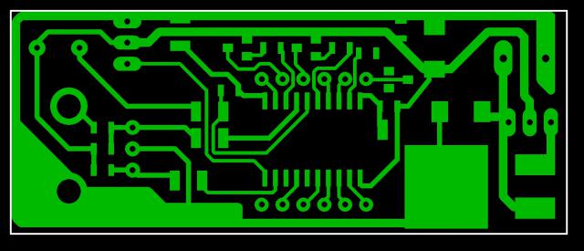
Detailed drawings of the board itself (of course, one-sided), ...
... an assembly drawing of the front ...

... and the back of the device have been developed .

Pay attention to jumpers J1-J4. These are resistors with zero resistance in the 1210 package.
As can be seen in the drawings on the front side are exclusively necessary controls, displays, as well as terminals for connecting power. A board can easily be made at home using LUT (do not forget to make the board's image mirror!). It looks like this for me:
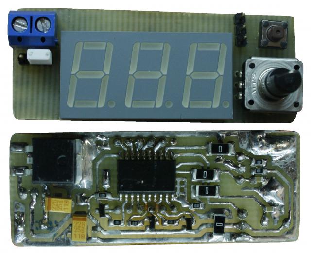
For programming, you will have to solder the wires to the board. I deliberately spread the legs of MOSI, MISO, SCK on the indicator, and left the pad on the RESET signal. When programming fuses, you do not need to change the firmware file, the circuit board and the list for purchase - at the end of the article.
As the advantages of your device, I want to note that not often do servo testers have an indicator, especially at a cost of less than 200r. In the future I want to add two more modes to the firmware - to determine the extreme angles and the automatic angle change mode.
And, of course, the board, the hex file and the list for purchase .
UPD:
The main article is now stored here .
In this article I want to share the experience of manufacturing a servo tester at home. My tester is controlled by an encoder, has several operating modes, and is also equipped with an indicator to display the current angle.
Scheme and work
The circuit is based on the Attiny2313 microcontroller . A seven-segment three-digit indicator with dynamic indication is connected directly to it through transistors. The current angle value and operation mode are displayed on the indicator. The button and encoder are used for control. When you press the button, one of the following modes is turned on:
1 - increment of the angle by 0.1 degrees
2 - by 1 degree
3 - by 10 degrees
4 - movement of the shaft between the extreme points (0 or 150 degrees)
Encoder changes the current angle up or down, depending on the direction of rotation. The button and one of the encoder pins are connected directly to the external interrupts of the MK. At the moment the button is pressed, the current mode is displayed for half a second. During these manipulations, pulses with a duration of 0.8 to 2.3 ms and a frequency of 50 Hz are present at the PD6 MK pin. I already wrote about the control signal generation algorithm itself . The circuit has the ability to be powered from a 5V DC source, or from 7-12V. The choice of food is set by a jumper.
Design
Detailed drawings of the board itself (of course, one-sided), ...
... an assembly drawing of the front ...
... and the back of the device have been developed .
Pay attention to jumpers J1-J4. These are resistors with zero resistance in the 1210 package.
Assembly and configuration
As can be seen in the drawings on the front side are exclusively necessary controls, displays, as well as terminals for connecting power. A board can easily be made at home using LUT (do not forget to make the board's image mirror!). It looks like this for me:
For programming, you will have to solder the wires to the board. I deliberately spread the legs of MOSI, MISO, SCK on the indicator, and left the pad on the RESET signal. When programming fuses, you do not need to change the firmware file, the circuit board and the list for purchase - at the end of the article.
Work video
Instead of a conclusion
As the advantages of your device, I want to note that not often do servo testers have an indicator, especially at a cost of less than 200r. In the future I want to add two more modes to the firmware - to determine the extreme angles and the automatic angle change mode.
And, of course, the board, the hex file and the list for purchase .
UPD:
The main article is now stored here .