Diode. Light-emitting diode. Zener diode
- Tutorial
Do not fit. Kill! (with)
I will try to explain the work with diodes, LEDs, and zener diodes on the fingers. Experienced electronics engineers can skip the article because they will not find anything new for themselves. I will not go into the theory of electron-hole conductivity of the pn junction. I believe that this learning approach will only confuse beginners. This is a bare theory, almost unrelated to practice. However, I am interested in theory and offer this article . Everyone is welcome under the cat.
This is the second article from the electronics cycle. I recommend reading also the first one , which tells about what electric current and voltage are.
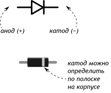
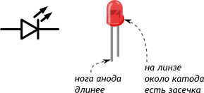
Diode - a semiconductor device having 2 leads for connection. Made, simply speaking, by connecting 2x semiconductors with different types of impurities, they are called donor and acceptor, n and p, respectively, so the diode contains a pn junction inside. Conclusions, usually consisting of tinned copper, called the anode (A) and cathode (K). These terms have gone since the time of electronic tubes and are used in writing to indicate the directivity of a diode. Much simpler graphic designation. The names of the findings of the diode will be remembered by themselves when applied in practice.
As I already wrote, we will not use the theory of the electron-hole conductivity of the diode. Just encapsulate this theory to a black box with two clips for connection. About the same way, programmers encapsulate work with third-party libraries, without going into e ... details of their work. Or, for example, when, using a vacuum cleaner, we do not go into details of how it works inside, it just works and one of the properties of the vacuum cleaner is important for us - to suck dust.
Consider the properties of the diode, the most obvious:
- From the anode to the cathode, this direction is called direct, the diode transmits current.
- From the cathode to the anode, in the opposite direction, the diode does not pass a current. (Actually, no. But more on that later.)
- When current flows in the forward direction, some voltage drops across the diode.

Perhaps these properties are already well known to you. But there are some additions. What is considered direct, and what is the opposite direction? Such an inclusion is called direct when the voltage at the anode is greater than at the cathode. The opposite is the opposite. Direct and reverse inclusion is a convention. In real-world circuits, the voltage on the same diode can change from direct to reverse and vice versa.
The silicon diode starts to transmit at least some significant current only when the voltage at the anode is about 0.65 V higher than at the cathode. No not like this. When at least some current flows, a voltage drop is formed on the diode, approximately equal to 0.65 V and higher.
Voltage 0.65 V - called the direct voltage drop across the pn junction. This is only an approximate average value, it depends on the current, the temperature of the crystal and the manufacturing technology of the diode. When changing the flowing current, it changes nonlinearly. To somehow identify this non-linearity graphically, manufacturers remove the current-voltage characteristics of the diode. In high-power high-voltage diodes, the voltage drop may be greater in 2, 3, etc. times This means that several pn junctions are connected in series inside the diode in series.
To determine the voltage drop, you can use the current-voltage characteristic (IVC) of the diode in the form of a graph. Sometimes these graphs are given in data sheets (datasheets) for real diode models, but more often they are not. On the first graphic I have, the VAC KD243A is shown below, although this is not important, they are all approximately similar.

On the graph, Upr is the direct voltage drop across the diode. Ipr - flowing through the diode current. The graph shows what the voltage drop across the diode will be when the nth current flows. But more often, real data-current-voltage characteristics are not shown in datalists, but the direct voltage drop indicated at a certain current is given. In the English literature, the voltage drop is referred to as forward voltage.
How to apply
The voltage drop across the diode is a bad characteristic for us, since this voltage does not perform useful work and is dissipated as heat on the diode body. The smaller the fall, the better. Typically, the voltage drop across the diode is determined based on the current flowing through the diode. For example, turn on the diode in series with the load. In fact, it will protect the circuit from over-flooding, in case the power supply is detachable. In the figure below, the 47 Ω resistor is taken as the protected circuit, although in reality it can be anything, for example, a section of a large circuit. As a power supply - 12 V battery.
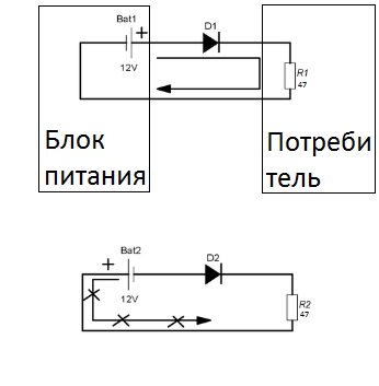
Suppose a load without a diode consumes 255 mA. In this case, it can be calculated according to Ohm’s law: I = U / R = 12/47 = 0.255 A or 255 mA. Although usually the consumption of a spherical scheme in a vacuum is already known, at least by the maximum characteristics of the power supply. Let us find on the VAC graph, indicated above, the voltage drop for the KD243A diode at 0.255 A of the flowing current, at 25 degrees. It is approximately 0.75 V. These 0.75 V will fall on the diode, and 12 to 0.75 = 11.25 V will remain to power the circuit - sometimes it may not be enough. As a bonus, you can find the power in the form of heat and losses released on the diode by the formula P = I * U = 0.75 * 0.255 = 0.19 W, where I and U are the current through the diode and the voltage drop across the diode.
What to do when the IVC schedule is not available? For example, for the popular diode 1n4007, only the forward voltage of 1 V at 1 A is indicated. It is necessary to use this value or measure the real drop. And if for any diode this value is not indicated, then an average of 0.65 V will come down. In reality, it is easier to measure this voltage drop with a voltmeter in the circuit than to look in the graphs. I think it is not necessary to explain that the voltmeter should be turned on for a constant voltage if a direct current flows through the diode, and the probes should touch the anode and cathode of the diode.
A little about other characteristics
In the previous example, if you turn the battery over, I mean to change the polarity, see the bottom picture, the current will not flow and the voltage drop across the diode in the worst case will be 12 V - the battery voltage. The main thing is that this voltage does not exceed the breakdown voltage of our diode, it is reverse voltage, it is breakdown voltage. And also one more condition is important: the current in the forward direction through the diode did not exceed the rated current of the diode, it is also forward current. These are the two main parameters by which the diode is selected: direct current and reverse voltage.
Sometimes datalists also indicate the power dissipation of the diode or the nominal power (power dissipation). If it is specified, then it cannot be exceeded. How to calculate it, we have already figured out the previous example. But if the power is not specified, then it is necessary to navigate the current.
They say that in the opposite direction the current through the diode does not flow, well, or almost does not flow. In fact, a leakage current, reverse current in English literature, flows through it. This current is very small, from several nanoamperes in low-power diodes to several hundred microamps, in high-power ones. Also, this current depends on the temperature and the applied voltage. In most cases, the leakage current does not play any role, for example, as in the previous example, but when you work with nanoampers and put some protective diode at the input of the operational amplifier, then oh can happen ... The circuit behaves completely differently as conceived.
Diodes also have some small parasitic capacitance capacitance. That is, in essence, it is a capacitor connected in parallel with the diode. This capacitance must be taken into account in fast processes when the diode operates in a circuit with tens to hundreds of megahertz.
Also a few words about the term "denomination". Typically, the rated current and voltage indicate that when these parameters are exceeded, the manufacturer does not guarantee the operation of the product, unless otherwise stated. And this is for all electronic components, not just for the diode.
What else can you do
There are many uses of diodes. Radio electronics developers usually invent their schemes from pieces of other schemes, the so-called building blocks. Here are a few options.
For example, the protection circuit of digital or analog inputs against overvoltage:

Diodes in this circuit during normal operation do not pass current. Only leakage current. But when the input voltage occurs with a positive half-wave, i.e. the input voltage becomes greater than the power input plus the forward voltage drop across the diode, the upper diode opens and the input closes on the power bus. If a negative half-wave voltage occurs, the lower diode opens and the input closes to ground. In this scheme, by the way, the less leakage and the capacity of the diodes, the better. Such protection schemes, as a rule, are in all modern digital circuits inside the crystal. And external powerful assemblies of TVS-diodes protect, for example, USB ports on motherboards.
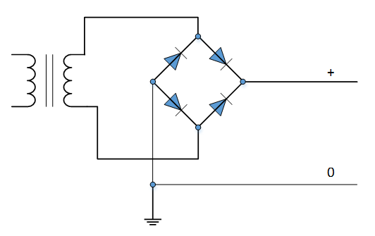
Also from the diodes can be assembled rectifier. This is a very common type of scheme and hardly any of the readers have heard about them. Rectifiers are half-wave, full-wave and bridge. With a half-wave rectifier, we have already met in our very first long-suffering example, when we considered over-res protection. It has no special advantages, except for the plus on the battery. One of the most important drawbacks that limits the use of the half-wave rectifier circuit in practice: the circuit only works with a positive half-wave voltage. Negative voltage completely cuts off and the current does not flow. “So what?”, You will say, “Such power will be enough for me!”. But no, if such a rectifier stands after the transformer, then the current will flow only in one direction through the windings of the transformer and, thus, the transformer iron will be additionally magnetized. The transformer can enter saturation and heat much more than it should be.
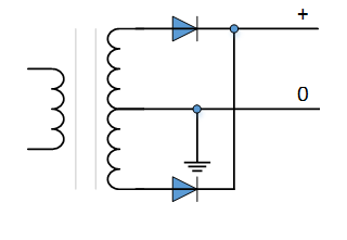
Full-wave rectifiers lack this disadvantage, but they need an average output winding of the transformer. Here, with a positive polarity of an alternating voltage, the upper diode is open, and with a negative voltage, the lower one. The efficiency of the transformer is not fully used.
Bridge circuits do not have both disadvantages. But now two diodes are connected to the current path at any one time: a forward diode and a reverse one. The voltage drop across the diodes doubles and is not 0.65-1V, but an average of 1.3-2V. Given this drop, the rectified voltage is considered.
For example, we need to get 18 volts of rectified voltage, which transformer to choose for this? 18 volts plus dip on diodes, let's take an average of 1.4 V, equal to 19.4 V. We know from the previous article that the amplitude value of the alternating voltage to the root is 2 times greater than its effective value. Therefore, in the secondary circuit of the transformer, the alternating effective voltage is 19.4 / 1.41 = 13.75V. Taking into account the fact that the voltage in the network can walk by 10%, as well as under load, the voltage will give a little bit, we will choose a 230/15 V transformer.
The power of the required transformer can be calculated from the load current. For example, we are going to connect a one-amp load to a transformer. This is if with a margin. Always keep a small margin, at 20-40%. Just by the power formula, you can find P = U * I = 15 * 1 = 15 VA, where U and I are the voltage and current of the secondary winding. If there are several secondary windings, then their powers are added up. Plus losses for transformation, plus margin, so we will choose a transformer of 20-40 VA. Although often transformers are sold with an indication of the current of the secondary windings, but checking for overall power will not hurt.
After the rectifier bridge, a smoothing capacitor is required, not shown in the figure. Do not forget about it! There are smart formulas for calculating this capacitor depending on the number of pulsations, but I would recommend the following rule: put a capacitor of 10,000 uF per current consumption current amp. The capacitor voltage is not less than the rectified voltage without load. In this example, you can take a capacitor with a nominal 25V.
The diodes in this circuit will choose a current> = 1A and reverse voltage, with a margin of more than 19.4 V, for example, 50-1000 V. You can use Schottky diodes. These are the same diodes, only with a very small voltage drop, which often amounts to tens of millivolts. But the lack of Schottky diodes - they are not released at more or less high voltages, more than 100V. More precisely, they have recently been released, but their cost is transcendental, and the advantages are no longer so obvious.
Light-emitting diode
Inside it is arranged quite differently than a diode, but it has the same properties. It only glows when current flows in the forward direction.
All difference from the diode in some characteristics. The most important is the direct voltage drop. It is much larger than 0.65 V in a normal diode and depends mainly on the color of the LED. Starting from red, the voltage drop of which averages 1.8 V, and ending with a white or blue LED, the drop in which is about 3.5 V. However, the invisible spectrum has these values wider.

In essence, the voltage drop here is the minimum ignition voltage of the diode. At a lower voltage, at the power supply, there will be no current and the diode will not light up. In high-power lighting LEDs, the voltage drop can be tens of volts, but this only means that there are many series-parallel diode assemblies inside the crystal.
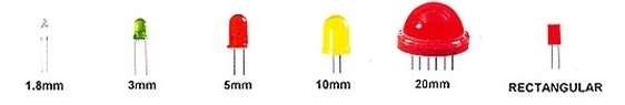
But now let's talk about the indicator LEDs, as the most simple. They are produced in various cases, most often in semi-circular, with a diameter of 3, 5, 10 mm.
Any diode glows depending on the current flowing. In fact, it is a current device. The voltage drop is automatically obtained. The current we ask ourselves. Modern indicator diodes more or less begin to glow at a current of 1 mA, and at 10 mA, eyes are already burning out. For powerful lighting diodes, you need to look at the documentation.
LED application
With only the appropriate resistor, you can set the desired current through the diode. Of course, you will also need a DC power supply unit, for example, a 4.5 V battery or any other PSU.
For example, let's set a current of 1 mA through a red LED with a voltage drop of 1.8 V.

The diagram shows the nodal potentials, i.e. voltage relative to zero. In which direction to turn on the LED, it will be best for us to tell the multimeter in the dial tone mode, as sometimes Chinese LEDs with twisted legs sometimes come across completely. When touching the multimeter test leads, in the right direction, the LED should glow dimly.
Since the red LED is applied, then 4.5 - 1.8 = 2.7V will fall on the resistor. This is known according to the second Kirchhoff law: the sum of the voltage drops on successive sections of the circuit is equal to the EMF of the battery, i.e. 2.7 + 1.8 = 4.5V. To limit the current to 1 mA, the Ohm law resistor must have a resistance R = U / I = 2.7 / 0.001 = 2700 Ohm, where U and I are the voltage across the resistor and the current we need. Do not forget to convert the values in SI units, in amps and volts. Since the output resistance ratings are standardized, we choose the closest standard rating of 3.3 kOhm. Of course, the current will change and it can be recalculated according to Ohm’s law I = U / R. But often this is not the point.
In this example, the current delivered by the battery is small, so that the internal resistance of the battery can be neglected.
With lighting LEDs all the same, only the currents and voltages are higher. But sometimes they no longer need a resistor, it is necessary to look at the documentation.
Something else about LED
In fact, shine is the main purpose of the LED. But there is another use. For example, the LED can act as a voltage reference. They are necessary, for example, to obtain current sources. As sources of reference voltage, as less noisy, use red LEDs. They are included in the scheme in the same way as in the previous example. Since the battery voltage is relatively constant, the current through the resistor and the LED is also constant, so the voltage drop remains constant. From the anode of the LED, where 1.8V, a tap is made and this reference voltage is used in other parts of the circuit.
For a more reliable stabilization of the current on the LED, with a pulsating voltage of the power source, a current source is put in the circuit instead of a resistor. But current sources and voltage sources are another article. Maybe someday I'll write it.
Zener diode
In English literature, the Zener diode is called Zener diode. All the same as the diode, in direct inclusion. But now let's talk only about the reverse inclusion. In the reverse connection, under the action of a certain voltage on the Zener diode, reversible breakdown occurs, i.e. current begins to flow. This breakdown is completely normal and the working mode of the Zener diode, in contrast to the diode, where when reaching the nominal reverse voltage, the diode simply failed. In this case, the current through the Zener diode in the breakdown mode can vary, and the voltage drop across the Zener diode remains almost unchanged.

What does this give us? In fact, it is a low-power voltage regulator. The Zener diode has all the same characteristics as the diode, plus the voltage stabilizing Ust or nominal zener voltage is also added. It is indicated at a certain current stabilization Ist or test current. Also in the documentation for the Zener diodes indicate the minimum and maximum current stabilization. When the current changes from minimum to maximum, the stabilization voltage floats somewhat, but only slightly. See current-voltage characteristics.

The working area of the zener diode is indicated in green. The figure shows that the voltage on the working area is almost unchanged, with a wide range of current variation through the zener diode.
To get to the work area, we need to set the current of the zener diode between [Ist. min - Ist. max] using a resistor in the same way as in the example with the LED (by the way, you can also use a current source). Only, unlike the LED, the zener diode is turned on in the opposite direction.
With less current than Ist. min the zener diode does not open, but with more than Ist. max - irreversible thermal breakdown will occur, i.e. the zener diode just burns out.
Calculation of the zener diode
Consider the example of our calculated transformer power supply. We have a power supply that delivers at least 18 V (in fact, there are more, because of the 230/15 V transformer, it is better to measure in the real circuit, but this is not the point) that can deliver a current of 1 A. It is necessary to power the load with the maximum consumption of 50 mA stabilized voltage of 15 V (for example, let it be some abstract operational amplifier - OU, they have about this consumption).
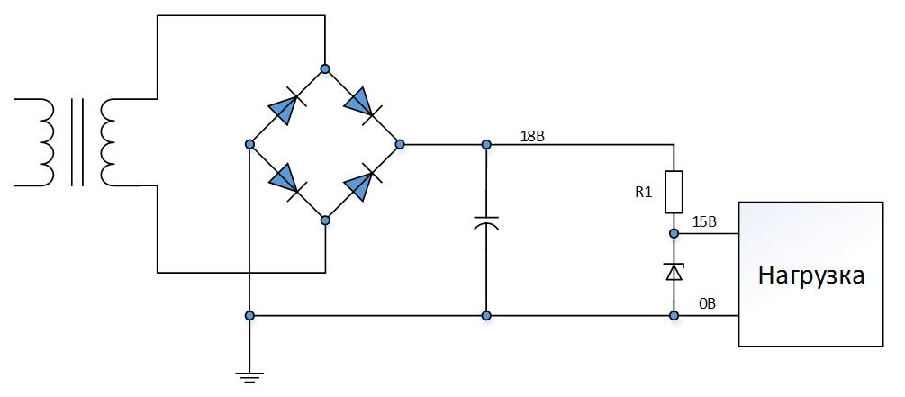
Such a weak load is chosen for a reason. Zener diodes are fairly low-power stabilizers. They must be designed so that through them could pass without overheating the entire load current plus the minimum stabilization current Ist. min. This is necessary because the current after the resistor R1 is divided between the zener diode and the load. In the load, the current can be non-constant, or the load can be switched off completely from the circuit. In fact, it is a parallel stabilizer, i.e. all the current that does not go into the load, will take over the Zener diode. This is like the first Kirchhoff law I = I1 + I2, only here I = Iagr + Ist. min.
So, choose a Zener diode with a stabilization voltage of 15 V. A resistor (or current source) is always needed to set the current through the Zener diode. On the resistor R1 will fall 18 - 15 = 3 V. A current Iagr will flow through the resistor R1. + Is. min. Take Ist. min = 5 mA, this is approximately enough current for all zener diodes with a stabilization voltage of up to 100 V. Above 100 V you can take 1 mA or less. You can take ist. min and more, but it will only be useless to heat the zener diode.
So, Ir1 = Inagram flows through R1. + Is. min = 50 + 5 = 55 mA. According to Ohm’s law, we find the resistance R1 = U / I = 3 / 0.055 = 54.5 Ohm, where U and I are the voltage across the resistor and the current through the resistor. Choose from the nearest standard series resistance of 47 ohms, there will be a little more current through the zener diode, but that's okay. It can even be calculated, the total current: Ir1 = U / R = 3/47 = 0.063 A, then the minimum current of the zener diode: 63 - 50 = 13 mA. The power of the resistor R1: P = U * I = 3 * 0,063 = 0,189 watts. Choose a standard 0.5 watt resistor. I advise, by the way, not to exceed the power of resistors of approximately Pmax / 2, they will live longer.
The Zener diode also dissipates power in the form of heat, while in the worst case it will be equal to P = Ust * (Iagr + Ist.) = 15 * (0.050 + 0.013) = 0.945 watts. Zener diodes produce at different power, the nearest 1W, but then the temperature of the case with a consumption of about 1W will be about 125 degrees C, it is better to take with a margin of 3 watts. Zener diodes produce 0.25, 0.5, 1, 3, 5 W, etc.
The first query in google “Zener diode 3W 15V” issued 1N5929BG. Next, look for "datasheet 1N5929BG". According to its datasheet, it has a minimum stabilization current of 0.25 mA, which is less than 13 mA, and a maximum current of 100 mA, which is more than 63 mA, i.e. fits into its operating mode, so it suits us.
In general, this is the whole calculation. Yes, the stabilizer is imperfect, its internal resistance is not zero, but it is simple and cheap and it works guaranteed in the specified current range. And since this is a parallel stabilizer, the current of the power supply will be constant. More powerful stabilizers can be obtained by powering the Zener diode with a transistor, but this is the topic of the next article about transistors.
Check the Zener diode for breakdown with a conventional multimeter, as a rule, is impossible. With more or less high-voltage zener diode just not enough voltage on the probes. The only thing that can be done is to ring it for the presence of a normal diode conduction in the forward direction. But this indirectly guarantees the performance of the device.
Still zener diodes can be used as sources of reference voltage, but they are noisy. For these purposes, they produce special low-noise zener diodes, but in my understanding, their price rolls over for a piece of silicon, it is better to add and buy an integral source with the best parameters.
There are also many semiconductor devices similar to a diode: a thyristor (controlled diode), a triac (symmetrical thyristor), a dynistor (which is pulsed only after reaching a certain voltage), a varicap (with variable capacitance), something else. You will need the first in power electronics when building controlled rectifiers or active load controllers. And I haven’t come across the last 10 years, so I leave this topic for independent reading on the wiki, at least about the thyristor.