MSP430 Launchpad as server hardware status alarm
Specialists working with server hardware know how high demands are placed on uninterruptible power supplies and an air conditioning and air exchange system. Directly he himself was repeatedly faced with situations where the failure of a particular system led to the fall of the data center of one of the mobile operators of the CIS countries. In one of the situations, both the main and the backup power lines of the data center were de-energized, the diesel generators started up automatically, but the electricians did not switch a specific switch. UPSs kept the load until the last, and then more than 200 servers turned off. In another situation, the data center after switching off the power on the main line was switched to the backup, on which the voltage turned out to be reduced. This led to the refusal to start the air conditioners, which are powered bypass the UPS. The servers were disconnected from overheating, the HLR switch hung for a long time and restored full operation only after 2-3 days. All this led to the fact that up to a million subscribers remained without communication. I immediately answer the question: “What did the monitoring service do?” In the first situation, she considered the work done to the end, in the second she late noticed an alarm on one of the many monitors.
Since it was my duty directly to lift the server after such accidents and, to put it mildly, tired of hoping for a monitoring service, I began to look for a solution other than SNMP traps. After reviewing the manuals that came with the UPS and air conditioners, it was found that they all maintained dry contacts. It remains to find how to work with them. The MSP430 Launchpad from Texas Instruments came to the rescue.
For non-specialists, dry contacts act as switches / switches that make / break contacts under certain conditions. The manufacturer can lay down, for example, such conditions: general alarm (any malfunction with the equipment), lack of voltage at the input contacts, battery discharge, temperature increase. All this is described in detail in the manuals, the contact diagrams to which you need to connect are also given there.
These switches allow you to create the HIGH and LOW criteria for the microcontroller: if the contact is open, then relative to the ground we will have HIGH on the controller pin, if it is closed, then LOW will be formed. Such conditions make it possible to control the on / off of other pins on the board using the simple “if” operator. Without thinking twice, I decided to control the LEDs and the piezo squeaker in order to give an audible and visual alarm signal. After 5 minutes, based on the examples that came with the Energia environment, a sketch was compiled:
I will explain a little, in the server room there are 4 UPSs and 2 industrial air conditioners. They are connected as buttonPinX, LEDs are connected as ledPinX, tweeter is connected to tonePin. I think there will be no difficulties with further analysis of the sketch.
The alarm panels were planned to be installed in two rooms: in the office where the administrators are located, and in the monitoring center. It was a pity to use two boards for this, so I decided to parallelize the signal outputs. It was decided to make the delivery of signals to the premises rather unusual - with the help of the already laid network cables through the crossover cabinet and the outlet from the outlets. It turned out quite conveniently - 6 UTP cable cables are used for positive LED contacts, one for positive tweeter contact and the last for ground. I did not decide to connect the cables coming from the dry contacts of the equipment directly to the board, I used 10k ohm resistors. I was also afraid that over time the LEDs may burn out, since the current consumption according to the tester was 6mA, and the MSP430G2553 controller can provide up to 50mA at the output. I decided to use 390 ohm terminating resistors. As a result, the circuit turned out like this
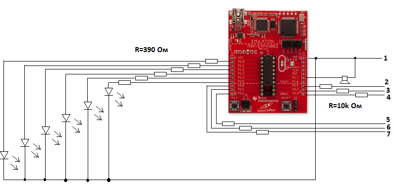
On the right, a loop of signal cables to the console is formed, in the real circuit I have 2 such loops for 2 remotes. The numbered conclusions go to the dry contacts of the UPS and air conditioners paired with the ground. Dry contacts are connected to the UPS, informing about the start of the battery discharge, at the same time this means that there is no input voltage either. On air conditioners to dry contacts of the general alarm.
The alarm system immediately went into operation, starting from the very first day starting to notify of a malfunction, as there are power problems almost daily. The plans include the inclusion of UART to read data on the status of pins and the formation of E-mail or SMS notification
Since it was my duty directly to lift the server after such accidents and, to put it mildly, tired of hoping for a monitoring service, I began to look for a solution other than SNMP traps. After reviewing the manuals that came with the UPS and air conditioners, it was found that they all maintained dry contacts. It remains to find how to work with them. The MSP430 Launchpad from Texas Instruments came to the rescue.
For non-specialists, dry contacts act as switches / switches that make / break contacts under certain conditions. The manufacturer can lay down, for example, such conditions: general alarm (any malfunction with the equipment), lack of voltage at the input contacts, battery discharge, temperature increase. All this is described in detail in the manuals, the contact diagrams to which you need to connect are also given there.
These switches allow you to create the HIGH and LOW criteria for the microcontroller: if the contact is open, then relative to the ground we will have HIGH on the controller pin, if it is closed, then LOW will be formed. Such conditions make it possible to control the on / off of other pins on the board using the simple “if” operator. Without thinking twice, I decided to control the LEDs and the piezo squeaker in order to give an audible and visual alarm signal. After 5 minutes, based on the examples that came with the Energia environment, a sketch was compiled:
const int ledPin0 =  P1_0;
const int ledPin1 =  P1_1;
const int ledPin2 =  P1_2;
const int ledPin3 =  P1_3;
const int ledPin4 =  P1_4;
const int ledPin5 =  P1_5;
const int buttonPin0 = P2_0;
const int buttonPin1 = P2_1;
const int buttonPin2 = P2_2;
const int buttonPin3 = P2_3;
const int buttonPin4 = P2_4;
const int buttonPin5 = P2_5;
const int tonePin = P1_7;
int buttonState0 = 0;
int buttonState1 = 0;
int buttonState2 = 0;
int buttonState3 = 0;
int buttonState4 = 0;
int buttonState5 = 0;
void setup() {
pinMode(ledPin0, OUTPUT);
pinMode(ledPin1, OUTPUT);
pinMode(ledPin2, OUTPUT);
pinMode(ledPin3, OUTPUT);
pinMode(ledPin4, OUTPUT);
pinMode(ledPin5, OUTPUT);
pinMode(buttonPin0, INPUT_PULLUP);
pinMode(buttonPin1, INPUT_PULLUP);
pinMode(buttonPin2, INPUT_PULLUP);
pinMode(buttonPin3, INPUT_PULLUP);
pinMode(buttonPin4, INPUT_PULLUP);
pinMode(buttonPin5, INPUT_PULLUP);
  }
void loop() {
  buttonState0 = digitalRead(buttonPin0);
  buttonState1 = digitalRead(buttonPin1);
  buttonState2 = digitalRead(buttonPin2);
  buttonState3 = digitalRead(buttonPin3);
  buttonState4 = digitalRead(buttonPin4);
  buttonState5 = digitalRead(buttonPin5);
  // LED P1_0
  if (buttonState0 == LOW) {
    digitalWrite(ledPin0, HIGH);
    tone(tonePin, 440, 200);
  }
  else {
    digitalWrite(ledPin0, LOW);
  }
  // LED P1_1
  if (buttonState1 == LOW) {
    digitalWrite(ledPin1, HIGH);
    tone(tonePin, 440, 200);
  }
  else {
    digitalWrite(ledPin1, LOW);
  }
  // LED P1_2
  if (buttonState2 == LOW) {
    digitalWrite(ledPin2, HIGH);
    tone(tonePin, 440, 200);
  }
  else {
    digitalWrite(ledPin2, LOW);
  }
  // LED P1_3
  if (buttonState3 == LOW) {
    digitalWrite(ledPin3, HIGH);
    tone(tonePin, 440, 200);
  }
  else {
    digitalWrite(ledPin3, LOW);
  }
  // LED P1_4
  if (buttonState4 == LOW) {
    digitalWrite(ledPin4, HIGH);
    tone(tonePin, 440, 200);
  }
  else {
    digitalWrite(ledPin4, LOW);
  }
  // LED P1_5
  if (buttonState5 == LOW) {
    digitalWrite(ledPin5, HIGH);
    tone(tonePin, 440, 200);
  }
  else {
    digitalWrite(ledPin5, LOW);
  }
}
I will explain a little, in the server room there are 4 UPSs and 2 industrial air conditioners. They are connected as buttonPinX, LEDs are connected as ledPinX, tweeter is connected to tonePin. I think there will be no difficulties with further analysis of the sketch.
The alarm panels were planned to be installed in two rooms: in the office where the administrators are located, and in the monitoring center. It was a pity to use two boards for this, so I decided to parallelize the signal outputs. It was decided to make the delivery of signals to the premises rather unusual - with the help of the already laid network cables through the crossover cabinet and the outlet from the outlets. It turned out quite conveniently - 6 UTP cable cables are used for positive LED contacts, one for positive tweeter contact and the last for ground. I did not decide to connect the cables coming from the dry contacts of the equipment directly to the board, I used 10k ohm resistors. I was also afraid that over time the LEDs may burn out, since the current consumption according to the tester was 6mA, and the MSP430G2553 controller can provide up to 50mA at the output. I decided to use 390 ohm terminating resistors. As a result, the circuit turned out like this
On the right, a loop of signal cables to the console is formed, in the real circuit I have 2 such loops for 2 remotes. The numbered conclusions go to the dry contacts of the UPS and air conditioners paired with the ground. Dry contacts are connected to the UPS, informing about the start of the battery discharge, at the same time this means that there is no input voltage either. On air conditioners to dry contacts of the general alarm.
The alarm system immediately went into operation, starting from the very first day starting to notify of a malfunction, as there are power problems almost daily. The plans include the inclusion of UART to read data on the status of pins and the formation of E-mail or SMS notification