Modbus touch switches: why you need it and how to use it in a smart apartment
- Tutorial
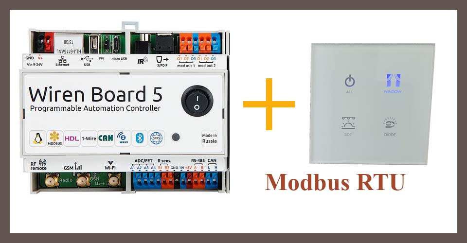
In budget systems, smart homes usually use standard switches - their type of output is also called "dry contact" . However, this is not the only option: in search of a beautiful switch, I came across devices with Modbus RTU protocol inside. In addition to the beautiful appearance, they allow you to customize the operation of each button, control the backlight in detail, and for connecting them to the central controller (I used Wiren Board 5 ) four wires are enough - power, ground and two lines for RS-485.
How to connect such a switch and configure the control of light and ventilation from it, see below. Also, the article will describe in detail how to work with Modbus devices in general.
An explanation from the Wiren Board marketer: this article was born from the topic created by Kallyanbl4 in our forum . After our request, he wrote a full article and allowed to publish it in our blog, for which he thanks a lot. All text is written by the author, except for the notes at the end.
Switch description
Having studied what is on the market now, I bought from the Chinese such interesting switches:
Their advantages:
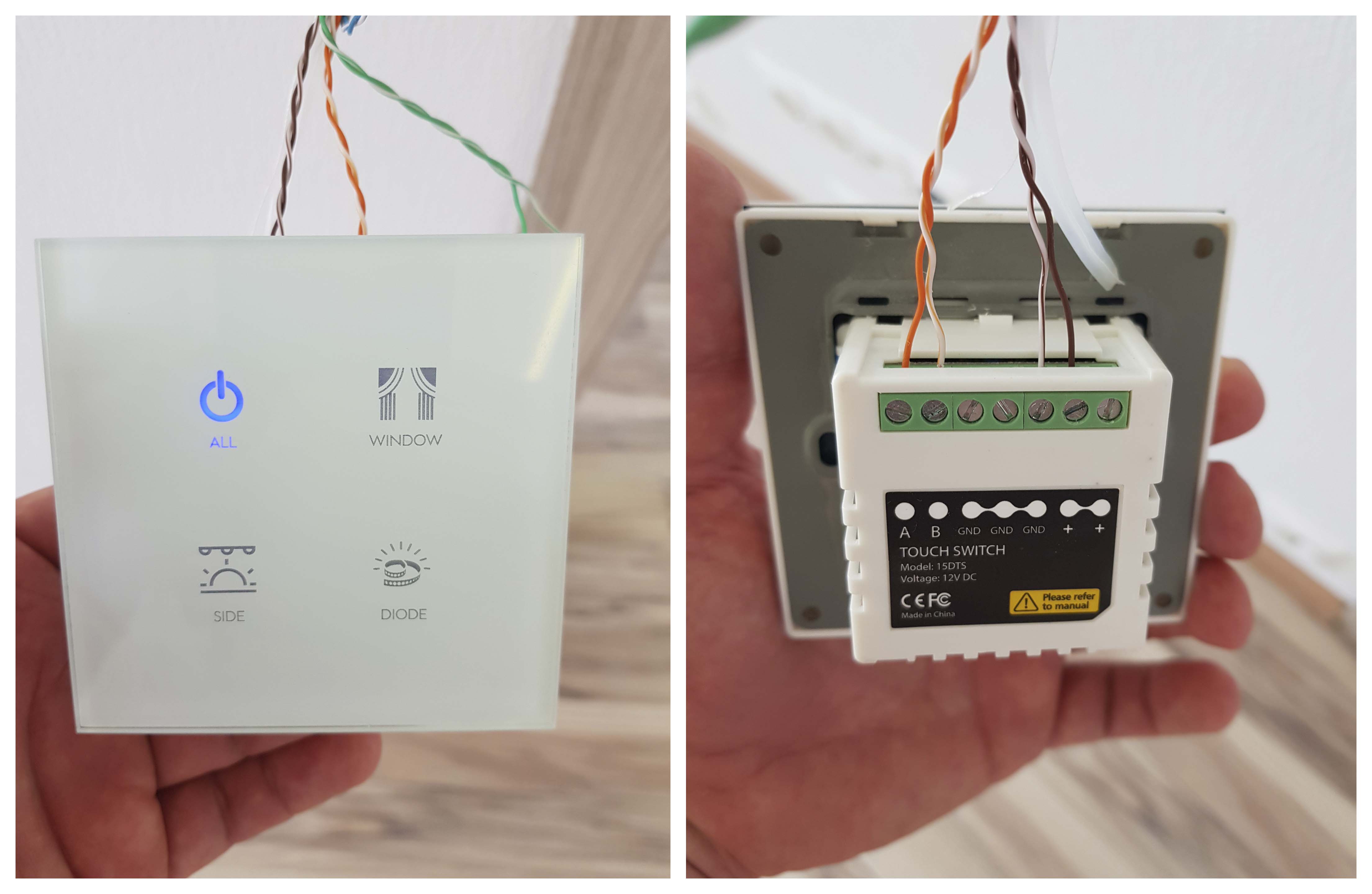
- good design;
- touch switches, flashing when pressed, illuminated in the dark in a pleasant white color;
- relatively small price - 2000 rubles per item. The price includes individual laser engraving;
- programmable switch - you can set the button for almost any action: turning on the light, controlling the LEDs, raising / lowering the curtain, ...
Technical characteristics of the switch:
- supply voltage - 12 V;
- data transfer rate - 19200 bps;
- the number of transmitted bits - 8;
- the number of stop bits - 1;
- parity control - no checking.
When working on Modbus RTU, the connected devices have so-called registers - cells in which information is stored. In the screenshot description of the registers for the four-
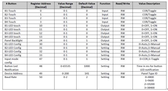
key switch: When you press one of the touch buttons, the values in the registers 0-3 will change from 0 to 1.
Switch Switching
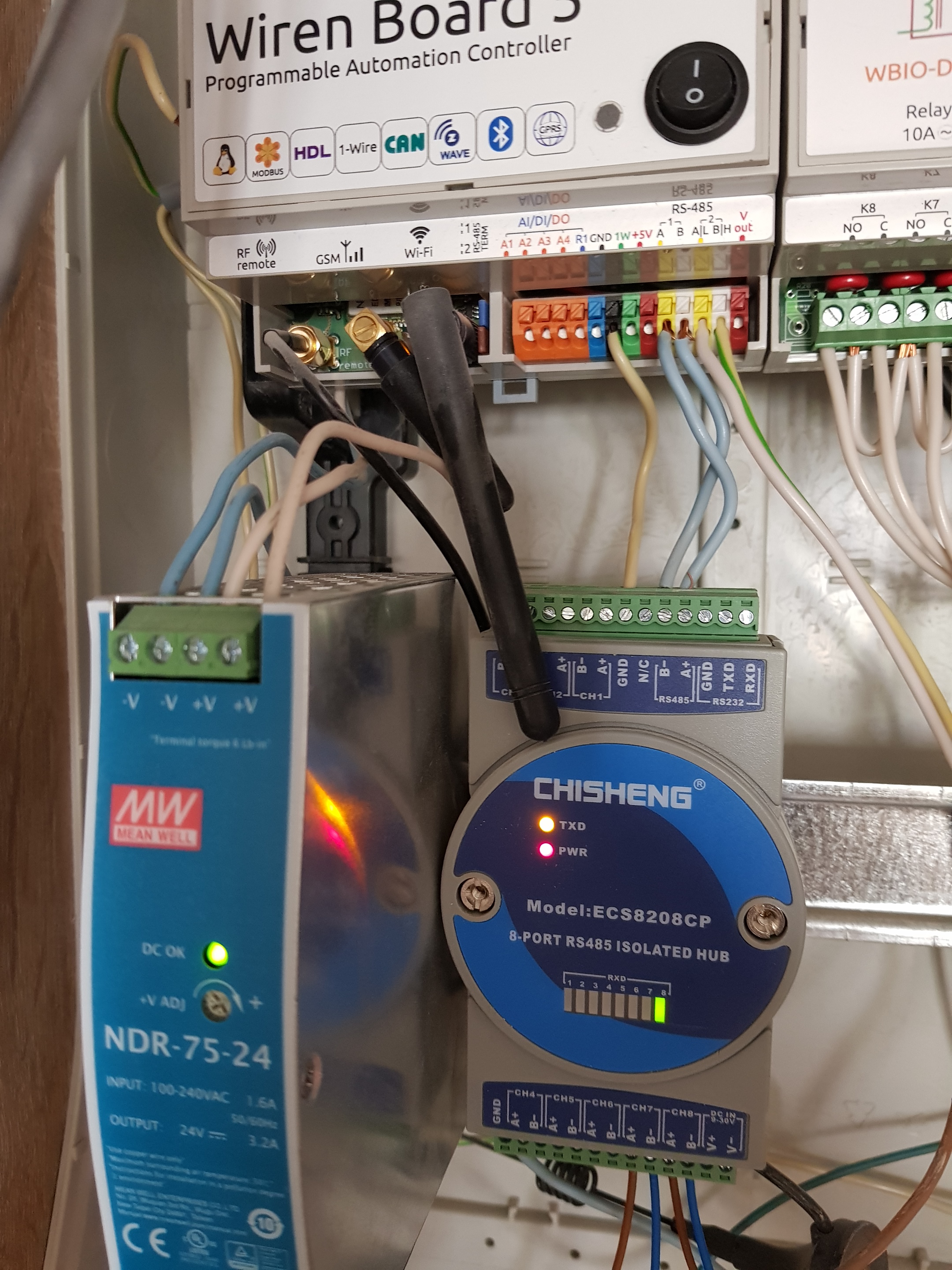
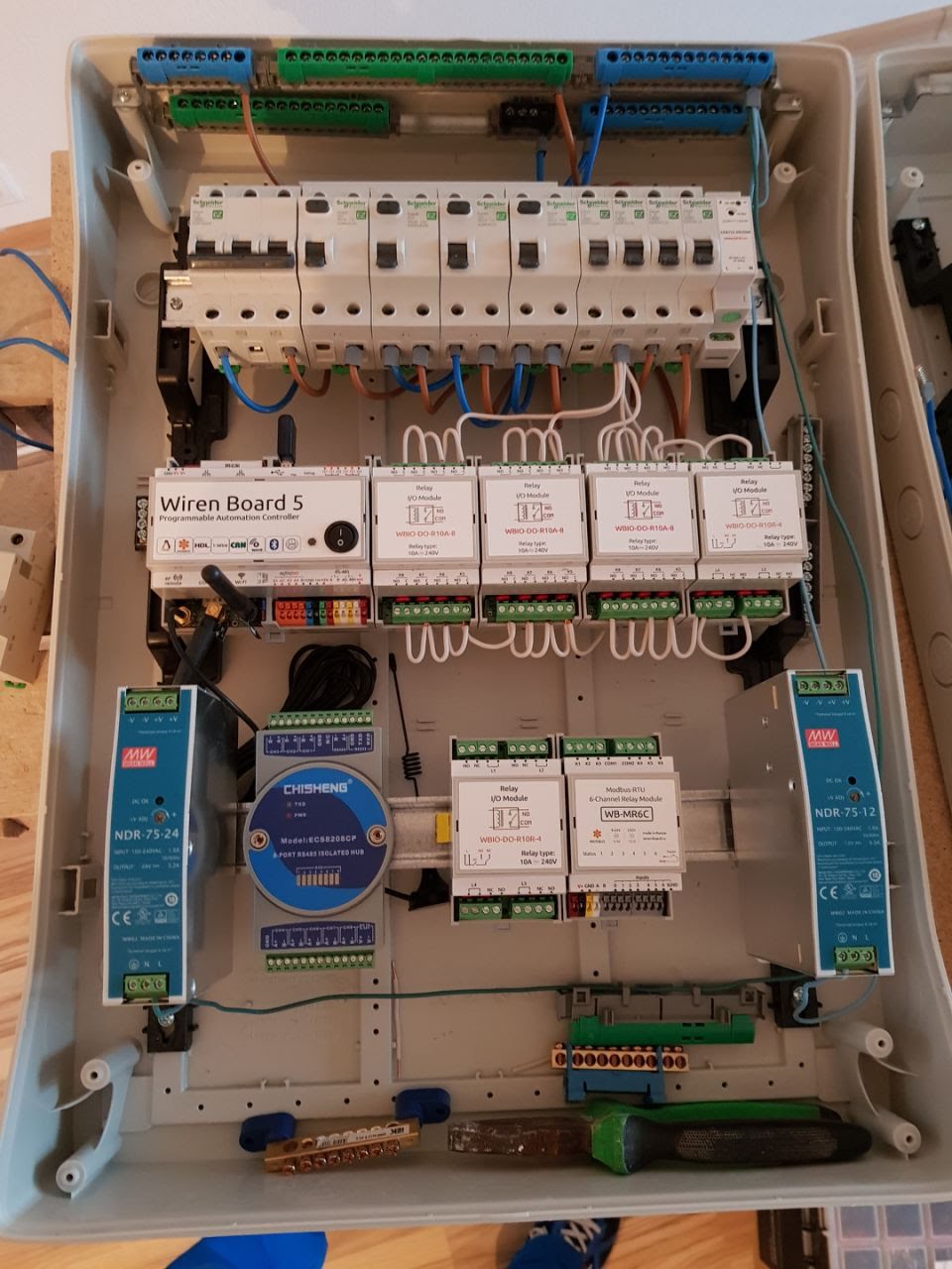
In the Wiren Board 5 controller, depending on the configuration, there are from two to four RS-485 ports. Switches (in my case there are 27 of them) need to be connected to these ports.
In this case, all switches can operate on one common bus. Switches can be connected in series, leading the cable from one switch to another, but I decided to switch all the cables in one shield.
The connecting cable is an eight-core Cat 5e UTP. You can use the four-core, but I usually do everything on the principle of "just in case." Other four-core cables can be considered, but an important point is that the cable must be shielded, because even with sufficiently low signal frequencies, losses and pickups are not excluded.
As a result, all the switches I have are interconnected as shown in the picture:
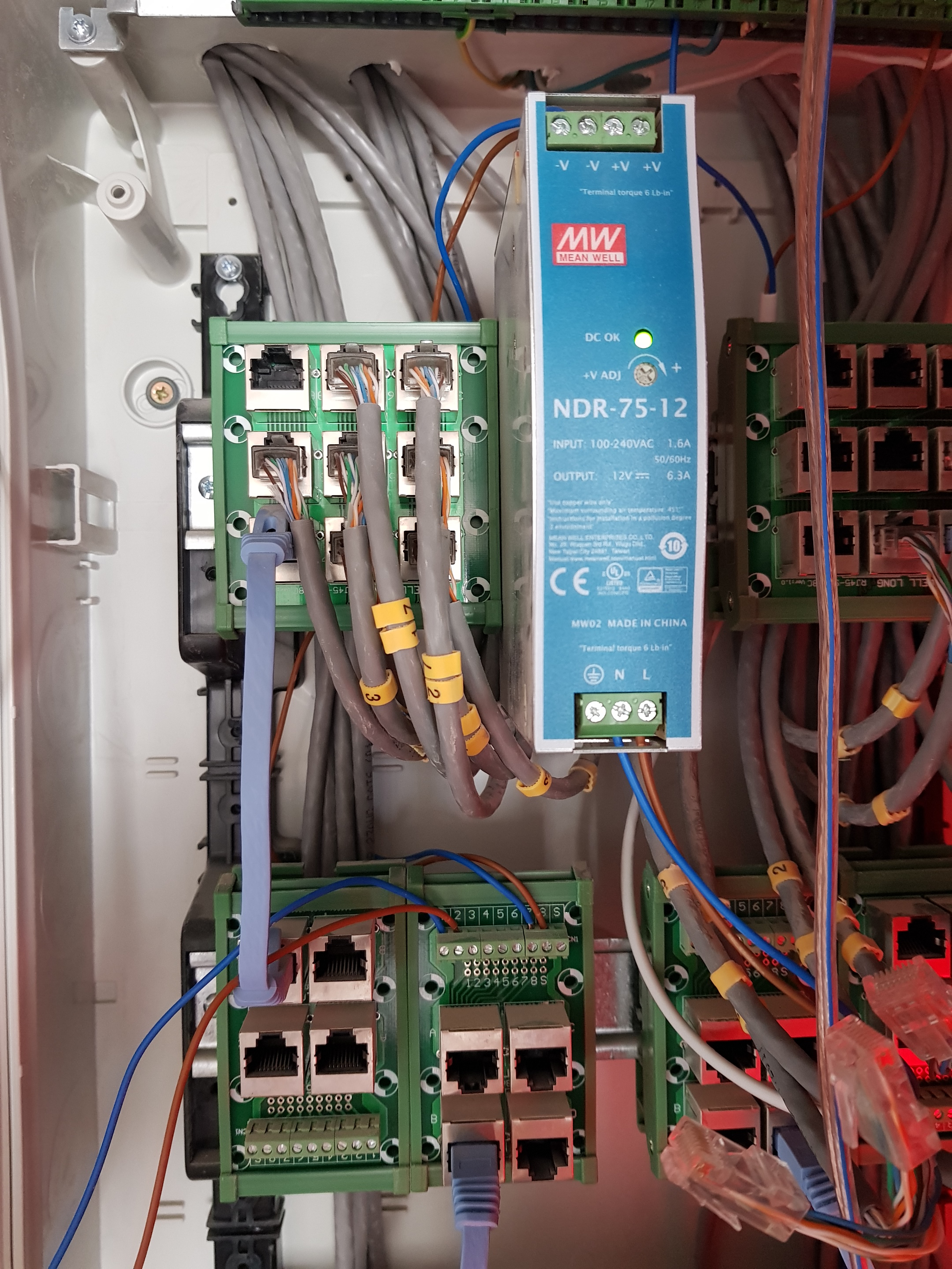
As can be seen from the figure, all the switches are interconnected using a passive UTP switch. Data (lines A and B) is transmitted through conductors 1 and 2 (orange and white-orange), 12 V power is connected to conductors 7 and 8 (brown and white-brown). Mean Well NDR-75-12 is used as a power source .
I did not know how the passive Chinese UTP switch would behave, so when designing the dashboard, I provided a place for an active RS-423 switch. I note that the scheme works through both passive and active switches. And even when they are connected together.
Light control with relay
According to my project, 27 independent devices (lights, fans), powered from 220 V, are planned in the apartment. Three relay modules WBIO-DO-R10A-8 and one WBIO-DO-R10R-4 were selected to control them . The choice is due to the fact that almost all the lighting in the apartment is LED, which differs from incandescent lamps with high starting current. The selected relays are capable of providing current switching up to 10 A per channel, which in my case is unnecessary - but, as mentioned earlier, “just in case with a margin”.
Switching the relay occurs through the web interface of the controller . The procedure is intuitive, no instructions or prompts are required.
Software part
Port File
From the description of the hardware of Wiren Board 5, we learn that it has two RS-485 ports corresponding to the device files / dev / ttyAPP1 and / dev / ttyAPP4 . In my case, the switch is connected to the / dev / ttyAPP1 port .
Device Address (Switch)
When communicating via Modbus RTU, each device is identified by its own unique number - the Modbus address. As a rule, the manufacturer specifies this address in the form of three digits on the device itself, but if there is no such number on the device, you can loop through the addresses from the command line (using the fact that the address is stored in the Modbus register 0x80):
root@wirenboard:~# service wb-mqtt-serial stop
root@wirenboard:~# for i in {1..247}; do modbus_client -mrtu /dev/ttyAPP1 --debug -a$i -t3 -r0x80 -s1 -pnone; done 2>/dev/null | grep Data:
The result should be in the form:
Data: 0x008e
The response was received in hexadecimal format and corresponds to 142 in decimal.
It should be noted that every time the modbus_client utility is called , the wb-mqtt-serial polling driver standard for the controller should be stopped ; otherwise, the modbus_client utility will not work.
Data exchange between the switch and the Wiren Board A
cycle has been written above that polls all possible Modbus addresses and returns the address value if the device is found. The cycle involved utility modbus_clientwhich is necessary for debugging connected devices. At this point, with the help of it, we make sure that everything is connected correctly, and the switch interacts with the controller properly. To do this, try to read the data in the register 0x01 switch:
root@wirenboard:~# service wb-mqtt-serial stop
root@wirenboard:~# modbus_client -mrtu /dev/ttyAPP1 --debug -a142 -s1 -pnone -b19200 -a142 -t0x03
(A description of the utility and its keys is in the controller documentation).
The result will be the following:
Opening /dev/ttyAPP1 at 19200 bauds (N, 8, 1)
[8E][03][00][64][00][01][DA][EA]
Waiting for a confirmation...
<8E><03><02><00><01><2C><5B>
SUCCESS: read 1 of elements:
Data: 0x0001
This result means that the register contains a discrete value 1. After pressing one of the switch buttons, the register value will change to the opposite value:
SUCCESS: read 1 of elements:
Data: 0x0000
If the result is observed, as in this paragraph, then everything is connected correctly, the switch and the controller understand each other.
Own driver for the switch
After we made sure that the controller and the switch understand each other, it is time to give a description of the switch keys at the program level. Developers suggest adding a description of the connected device to the /etc/wb-mqtt-serial.conf file or creating your own template as /usr/share/wb-mqtt-serial/templates/config-*.json
I went the second way, my the template looks like this:
{
    "device_type": "4-band-switch",
    "device": {
        "name": "4-band-switch",
        "id": "4bsw",
        "enabled": true,
        "channels": [{
                "name": "All",
                "reg_type": "holding",
                "address": "0x00",
                "type": "switch"
            },
            {
                "name": "Window",
                "reg_type": "holding",
                "address": "0x01",
                "type": "switch"
            },
            {
                "name": "Side",
                "reg_type": "holding",
                "address": "0x02",
                "type": "switch"
            },
            {
                "name": "Diode",
                "reg_type": "holding",
                "address": "0x03",
                "type": "switch"
            }
        ]
    }
}
A detailed description of the template written above is in the description of the wb-mqtt-serial driver . Let's briefly understand the fields:
- "Name": "All" - the name of the button. If the pattern is written correctly, this button will appear in the Settings tab with the address / devices / 4bsw_142 / controls / All
- "Reg_type": "holding" - the type and size of the register. The switch uses “holding” - a 16-bit register available for reading and writing.
- "Address": "0x00" - the address of the switch register from which the controller will read the data.
- “Type”: “switch” - how the switch will be displayed in the web interface. In the case of "switch" - in the form of a discrete switch.
Save the template to the controller. After that, in the web interface section (Configs -> /etc/wb-mqtt-serial.conf) you can add a new device with this pattern (4-band-switch). Add our first switch and click Save.
The rule that turns on the relay when the switch button is pressed
Inside the controller, the status of all connected devices is described by MQTT messages . Devices are also controlled by sending MQTT messages. Clients of the MQTT message queue (broker) are both the web interface and the rules engine .
For clarity, let's see how the web interface processes the incoming message. Open the Settings tab of the web interface and observe what happens when you press the All button on the switch: the Modbus register value changes inside the switch, the wb-mqtt-serial driver polls the switch, and in accordance with the device template 4-band-switch sends an MQTT message in the topic / devices / 4bsw_142 / controls / All - and on the Settings page, the value in the topic / devices / 4bsw_142 / controls / Allinstantly change from 0 to 1.
Consider the second client - the rules engine. The engine, like the web interface, works with a message queue, and can react to changes in value — the whenChanged function is used for this . In my case, the rule looked like this:
//Коридор и гостиная
defineRule("switch_all", {
    whenChanged: "4bsw_142/All",
    then: function(newValue, devName, cellName) {
        dev["wb-gpio"]["EXT3_R3A2"] = newValue;
        dev["wb-gpio"]["EXT3_R3A5"] = newValue;
        dev["wb-gpio"]["EXT1_R3A1"] = newValue;
        dev["wb-gpio"]["EXT1_R3A2"] = newValue;
        dev["wb-gpio"]["EXT1_R3A5"] = newValue;
        dev["wb-gpio"]["EXT2_R3A8"] = newValue;
        dev["wb-gpio"]["EXT3_R3A7"] = newValue;
    }
});
//маленькая комната
defineRule("switch_window", {
    whenChanged: "4bsw_142/Window",
    then: function(newValue, devName, cellName) {
        dev["wb-gpio"]["EXT4_ON4"] = newValue;
        //    dev["wb-gpio"]["EXT3_R3A6"] = newValue;//    dev["wb-gpio"]["EXT3_R3A7"] = newValue;
    }
});
//Санузлы
defineRule("switch_side", {
    whenChanged: "4bsw_142/Side",
    then: function(newValue, devName, cellName) {
        dev["wb-gpio"]["EXT1_R3A3"] = newValue;
        dev["wb-gpio"]["EXT1_R3A4"] = newValue;
        dev["wb-gpio"]["EXT2_R3A1"] = newValue;
    }
});
//Кухня
defineRule("switch_diode", {
    whenChanged: "4bsw_142/Diode",
    then: function(newValue, devName, cellName) {
        dev["wb-gpio"]["EXT2_R3A2"] = newValue;
        dev["wb-gpio"]["EXT2_R3A3"] = newValue;
        dev["wb-gpio"]["EXT3_R3A3"] = newValue;
    }
});
All questions will be glad to answer in the comments.
Marketer Notes
- Laying the RS-485 line is better with a KSPEVG 2x2x0.35 cable (it costs only 30 rubles per meter), and not a star, but a bus.
- We advise to be more careful with LED lamps - their starting current can exceed the rated one by 150 (!) Times (this will be a separate article) - take a look at the powerful WB-MR6 relay modules : current 16 A per channel, including starting current up to 800 (!) ampere in modification S.