Quantum computer: one photon to rule by all

The history of computing, which we now call simply a server or computer, began many centuries ago. With the passage of time and the development of technology, computers have also improved. Improved performance, speed and even appearance. Any computer basically implements certain laws of the natural sciences, such as physics and chemistry. Delving into any of these sciences, researchers are finding new and new ways to improve computing systems. Today we will get acquainted with a study aimed at the implementation of the use of photons in quantum computers. Go.
Theoretical basis
The phrase "quantum computer" has already ceased to be shocking, although it sounds like science fiction. However, there is nothing fantastic in it, at least from a literary point of view. A quantum computer exploits quantum superposition and quantum entanglement. In simple words, quantum superposition is a phenomenon when the quantum states of a system are mutually exclusive. If we are not talking about particles, about something “bigger”, then we can mention Schrodinger's cat.
A little bit about Schrödinger's cat
Данный теоретический эксперимент был описан самим Шрёдингером довольно подробно и сложно, в какой-то степени. Упрощенный вариант звучит так:
Есть стальная коробка. В коробке кот и механизм. Механизм — счетчик Гейгера с очень малым количеством радиоактивного вещества. Данное вещество так мало, что за 1 час может распасться 1 атом (а может и не распасться). Если это происходит, то считывающая трубка счетчика разряжается и срабатывает реле, освобождающее молоток, который висит над колбой с ядом. Колба разбивается, и яд убивает кота.
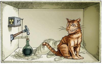
Иллюстрация эксперимента
Теперь пояснение. Мы не видим что происходит в коробке, мы не можем повлиять на процесс даже своими наблюдениями. Пока мы не откроем коробку, мы не знаем жив кот или мертв. Таким образом, утрируя, можно сказать, что для нас кот в коробке находится в двух состояниях одновременно: он и жив, и мертв.
Очень интересный эксперимент, раздвигающий границы квантовой физики.
Еще более необычным можно считать парадокс Вигнера. К всем вышеуказанным переменным эксперимента добавляются некие друзья лаборанта, что проводит данный эксперимент. Когда он открывает коробку и узнает точное состояние кота, его товарищ, находясь в другом месте, этого состояния не знает. Первый должен сообщить второму, что кот жив или мертв. Таким образом, пока все во Вселенной не будут знать точного состояния бедного животного, оно будет считаться и мертвым, и живым одновременно.
Есть стальная коробка. В коробке кот и механизм. Механизм — счетчик Гейгера с очень малым количеством радиоактивного вещества. Данное вещество так мало, что за 1 час может распасться 1 атом (а может и не распасться). Если это происходит, то считывающая трубка счетчика разряжается и срабатывает реле, освобождающее молоток, который висит над колбой с ядом. Колба разбивается, и яд убивает кота.

Иллюстрация эксперимента
Теперь пояснение. Мы не видим что происходит в коробке, мы не можем повлиять на процесс даже своими наблюдениями. Пока мы не откроем коробку, мы не знаем жив кот или мертв. Таким образом, утрируя, можно сказать, что для нас кот в коробке находится в двух состояниях одновременно: он и жив, и мертв.
Очень интересный эксперимент, раздвигающий границы квантовой физики.
Еще более необычным можно считать парадокс Вигнера. К всем вышеуказанным переменным эксперимента добавляются некие друзья лаборанта, что проводит данный эксперимент. Когда он открывает коробку и узнает точное состояние кота, его товарищ, находясь в другом месте, этого состояния не знает. Первый должен сообщить второму, что кот жив или мертв. Таким образом, пока все во Вселенной не будут знать точного состояния бедного животного, оно будет считаться и мертвым, и живым одновременно.
As for quantum entanglement, then the states of two or more particles depend on each other. That is, speaking of the same photons, if a change in the spin of a single particle leads to the fact that it becomes positive, then the second one automatically becomes negative, and vice versa. At the same time, having measured the state of the first particle, we instantly deprive the second particle of the state of quantum entanglement.
It operates a quantum computer not in bits, but in qubits, differing from the first in that they can simultaneously be in two states, 0 and 1. This allows information to be processed much faster.
With photons, everything is a little easier. A photon is a “piece of light,” if it is very exaggerated. A more scientific definition is an elementary particle of electromagnetic radiation capable of carrying electromagnetic interaction.
The reverse side of the coin
Photons are excellent carriers of quantum information, but the lack of a deterministic * photon-photon interconnection limits their use in quantum computers and networks.
Deterministic systems * are systems in which processes are interconnected in such a way that cause-and-effect sequence can be traced. In other words, these are systems where incoming data (for example, tasks) fully correspond to outgoing data (the result of a decision).This study could not have happened at all if it were not for the recent discoveries in the field of light-matter interaction by means of neutral trapped atoms, which allowed the use of optical nonlinearities * in the single-photon mode.
Optical nonlinearity * is explained by the nonlinear reaction of the polarization vector to the electric field intensity vector of the light wave. You can observe this when using lasers, since they can generate a beam of high intensity light.This technique is associated with the problems of implementing devices in a compact form, since its implementation requires very large and extremely complex laser traps to set up. In addition, neutral atoms operate with low throughput.
Optical nonlinearity on the example of the generation of a second optical harmonic (second harmonic wave)
Another option, which has also been shelved for the time being, is systems based on nonlinear quantum electrodynamics. Since such systems operate exclusively in the microwave mode, it is extremely problematic to transfer them to the optical mode.
Other researchers decided to dig even deeper, almost literally. The use of nanophoton systems in which photons interact with nanometer elements (in this case with quantum emitters) is a very attractive way to implement single-photon nonlinearity in compact solid-state devices. However, so far in such experiments emitters are used, represented by a two-level atomic system, limited by a compromise between throughput and delay, which makes the implementation of monochromatic switches impossible.
As a conclusion, all previous studies had some positive results, which, unfortunately, were associated with certain problems of implementation or interaction of systems.
Basics of research
In this study, a single-photon switch and a transistor were demonstrated, implemented by interfacing a solid-state quantum qubit and a nanophoton resonator.
One of the main elements of the experiment is a spin qubit, consisting of a single electron in a charged quantum dot * .
A quantum dot * (or “artificial atom”) is a semiconductor particle. Due to the extremely small size of its optical and electronic properties are very different from those of larger particles.
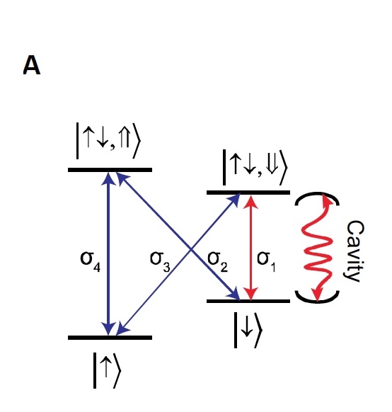
Image No. 1a.
Image 1a shows the level structure of a quantum dot, including two ground states * with opposite spins, which forms a stable quantum memory. These states are labeled as: | ↑⟩ and | ↓⟩ .
The ground state * - in quantum mechanics it is a stationary state, when the energy level and other quantities do not change, with the lowest energy.Also on the image are marked excitation states * , which contain a pair of electrons and one hole * with opposite spins. They are denoted as follows: | ↑ ↓, ⇑⟩ and | ↑ ↓, ⇓⟩ .
Excitation * - indicates the transition of the system from the ground state to a state with a higher energy.
Hole * is a quasi-particle, a carrier of a positive charge equal to an elementary charge in semiconductors.
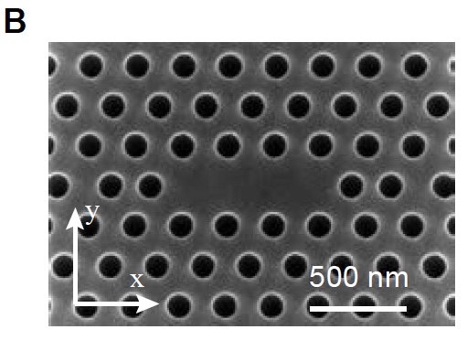
Image # 1b
Image 1b is a snapshot of a manufactured nanophoton resonator taken by a scanning electron microscope. By operating the Vogt effect * , a spin-dependent compound was obtained by applying a magnetic field (5.5 T) along the plane of the device.
Vogta effect * - the occurrence of birefringence of an electromagnetic wave during its propagation in solids.Due to the measurements of cross-polarized reflectivity, it was also possible to determine the compound strength ( g ), the decay rate of the energy of the nanophoton resonator ( k ) and the decoherent dipole transition ( y ):
- g /2π=10.7 app0.2 GHz
- to /2π=35.5 for0.6 GHz
- y /2π=3.5 equal0.3 GHz
In this case, g> k / 4 is a condition determining that the device has switched to the strong and stable connection mode.
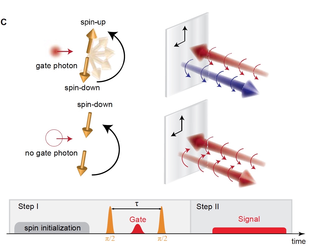
Image No. 1c
The image 1c (top left) graphically demonstrates the principles of operation of a single-photon switch and a transistor. As we see, if the gate pulse does not contain photons, then the spin remains in the “down” position. If one photon is present, then the spin moves to the up position. As a consequence, the spin state controls the reflection coefficient of the nanophoton resonator, thereby changing the polarization of the photons of the reflected signal.
The entire sequence of pulses is shown in image 1c (bottom). Now let's take a little more detail about each step.
- At the beginning there is a quantum dot in the superposition of its ground spin state. Calculated using the formula (| ↑⟩ + | ↓⟩) / √2 . This is achieved by applying an initialization pulse for optical pumping of the spin, which puts it in the “down” state.
- Next, an optical rotational pulse is applied, which creates π / 2 spin rotation.
- For some time ( τ ) the system develops freely.
If this time is set as an integer + half the spin procession period, then in the absence of a gate photon, the spin will transition to the state (| ↑⟩ - | ↓⟩) / √2 , and the second rotational impulse will turn the spin back to the “down” state. If the gate photon is reflected from the resonator, then it forms a relative π-phase shift between the “up” and “down” states, which reflects the spin along the axis ( x ) of the Bloch sphere * . Thus, the second rotational impulse will translate the spin into the "up" state. - One more rotational impulse identical to the first one is applied.
- Between these two pulses, a gate pulse is introduced.
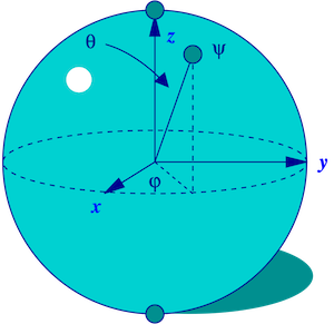
Bloch sphere * - in quantum mechanics it is used as a method of geometrical representation of the qubit state space.
- At the end of the process, the signal field is reflected from the resonator and is subjected to polarization rotation, which directly depends on the spin state.
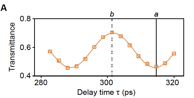
Image No. 2a
The diagram above shows the transmittance of the signal field passing through the polarizer as a function (τ) in the absence of a gate pulse.
The transmittance contrast is determined by the formula: δ = T up - T down
Where T up and T down are the transmittances of the signal field at the moments when the spin transitions to the “up” ( up ) and “down” ( down ) states using two rotational pulses corresponding to the maximum and the minimum value of the transmittance in the oscillation.
The constant value δ = 0.24 ± 0.01. It is very different from the ideal one because of the inaccurate spin state F = 0.78 ± 0.01 and due to limited cooperativity C = 2 g 2 / ky = 1.96 ± 0.19.
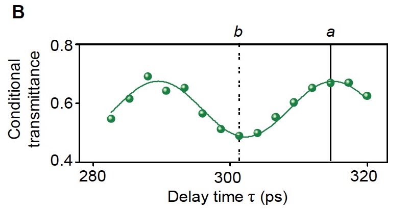
Image # 2b
Graph 2b shows the case when a 63-ps pulse is applied, containing approximately 0.21 photons per pulse associated with a resonator. In order to make sure that one photon regulates the transmittance, two-photon coincidences between the gate and signal photons were measured.
Green dots - measured transmittance of the signal, due to the detection of the reflected gate photon as a function ( τ ).
Green Line- numerical correspondence of the model displayed on the graph 2a .
The vertical line (a) in graphs 2a and 2b is the designation of the state when the spin is subjected to a half-integer number of rotations around the Bloch sphere during the free development period. In such a situation, the gate photon causes the polarization of the signal field to rotate and redirect through the polarizer.
Vertical line (b) in graphs 2a and 2bThis is a display of the second operating state, at which switching operations are possible. In this embodiment, the reverse switching behavior is observed when the gate photon prevents the signal field from rotating, thereby reducing the transmittance.
In both cases, the gate pulse causes a change in the transmittance of the signal by 0.21 ± 0.02. To consider the gate photon to be ideal, this indicator should be equal to 0.24, as determined in the calculations, shown on graph 2a . In the case of a real experiment, the performance is worse due to the use of an attenuated (with damped oscillation) laser to create a gate pulse, which, although unlikely, may contain several photons.
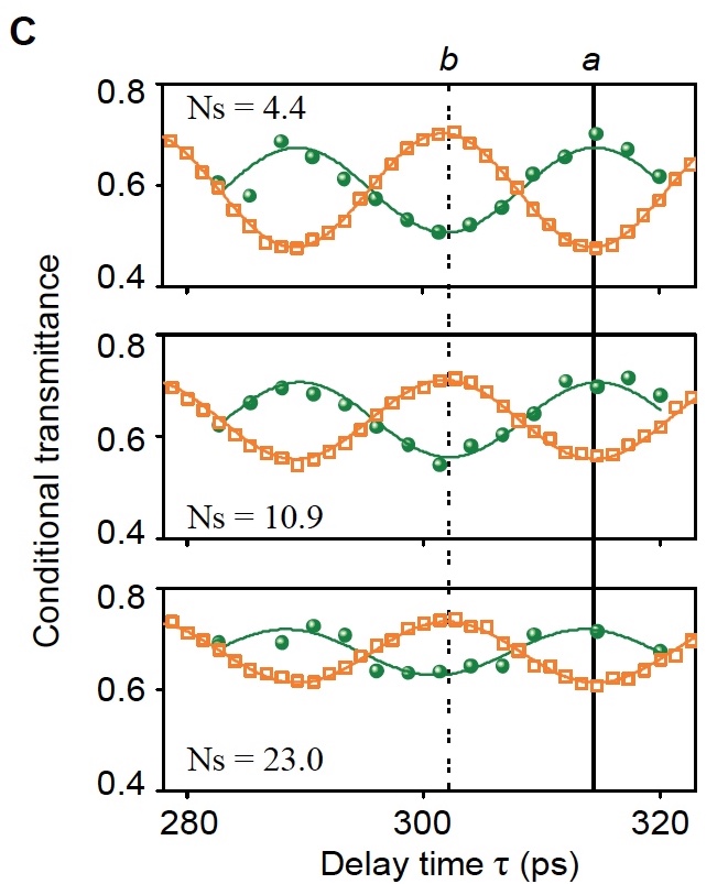
Image number 2c
The graph above displays the transmittance as a function of the delay time ( τ ) when the average value of the signal photons per pulse is set at 4.4 ± 0.5 (top), 10.9 ± 1.2 (middle), 23.0 ± 2.5 (bottom).
Green dots - transmittance due to the detection of a gate photon.
The orange squares are the transmittance without the gate pulse.
Green and orange lines - numerical correspondence to theoretical models from graphs 2a and 2b .
In all cases, the switching behavior is clearly observed.
Switching contrast calculations ( ξ) gave the following results: 0.22 ± 0.03, 0.17 ± 0.02 and 0.12 ± 0.02, in accordance with each schedule.
The main problem associated with the switching contrast is its decrease with an increase in the number of signal photons. This is due to the fact that each signal photon can reversely affect the spin through Raman scattering ( the Raman effect * ). This resets the state of the internal quantum memory.
The Raman effect * is the inelastic scattering of optical radiation when particles collide, which leads to a change in their state, the formation of new particles, the transformation into others, or the creation of new particles.
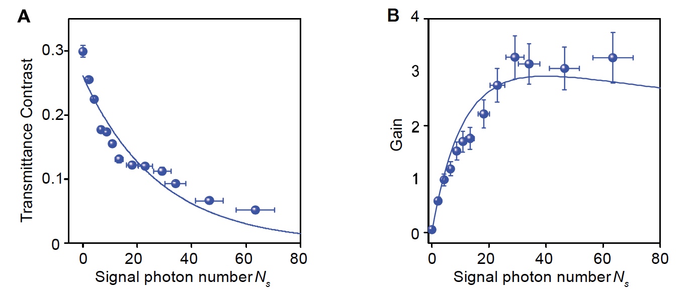
Image No. 3
In graph 3a, the blue dots show the measured transmission contrast, when there is no gate pulse, as a function of the average number of photons in the signal field. This is an indicator of the degree of self-switching triggered by a signal without a shutter. Blue lines indicate the numerical correspondence of the data of an exponential function of the form exp (-N s / N avg ) , where N avg is the average number of signal photons necessary to change the position of the spin. Calculations showed that N avg = 27.7 ± 8.3.
Another important property of transistors is the transmission ratio ( G ). Schedule2b (blue dots) demonstrates the growth of this indicator. The researchers managed to reach G = 3.3 ± 0.4 with the number of photons N s = 29.2 ± 3.2.
More detailed information regarding this study, as well as methods of calculation, are set out in the report, available here. I strongly recommend to read.
Epilogue
At the moment, the biggest obstacle in the process of implementing a full-fledged device based on this study is the loss of photons. However, scientists argue that this problem can be solved. Not them, so to other scientists. At the moment, there are a lot of studies aimed at optimizing quantum devices based on photons.
These studies, including those reviewed today, accumulate a theoretical basis supported by experiment. The theory is always followed by practical implementation. But this is possible only when a critical mass of knowledge is achieved that will allow to fully realize this or that idea.
The first steps have already been taken. Yes, these steps are small, but they are made by many scientists around the world, each in his own direction. And although their paths differ, the destination of this incredibly difficult, and at the same time fascinating path, is one.
Thank you for staying with us. Do you like our articles? Want to see more interesting materials? Support us by placing an order or recommending to your friends, a 30% discount for Habr's users for a unique analogue of the entry-level servers that we invented for you:The whole truth about VPS (KVM) E5-2650 v4 (6 Cores) 10GB DDR4 240GB SSD 1Gbps from $ 20 or how to share the server? (Options are available with RAID1 and RAID10, up to 24 cores and up to 40GB DDR4).
Dell R730xd 2 times cheaper? Only we have 2 x Intel Dodeca-Core Xeon E5-2650v4 128GB DDR4 6x480GB SSD 1Gbps 100 TV from $ 249 in the Netherlands and the USA! Read about How to build an infrastructure building. class c using servers Dell R730xd E5-2650 v4 worth 9000 euros for a penny?


