Grounding What is it and how to do it (part 1)

My story will consist of three parts.
1 part. Grounding
(general information, terms and definitions)
2 part. Traditional methods of building grounding devices
(description, calculation, installation)
3 part. Modern methods of building grounding devices
(description, calculation, installation)
In the first part (theory) I will describe the terminology, the main types of grounding (purpose) and the requirements for grounding requirements.
In the second part (practice) there will be a story about traditional solutions used in the construction of grounding devices, listing the advantages and disadvantages of these solutions.
The third part (practice) in a sense will continue the second. It will contain a description of new technologies used in the construction of grounding devices. As in the second part, listing the advantages and disadvantages of these technologies.
If the reader possesses theoretical knowledge and is only interested in practical implementation, he should skip the first part and start reading from the second part.
If the reader has the necessary knowledge and wants to get acquainted only with the latest news, it is better to skip the first two parts and immediately proceed to reading the third.
My view of the described methods and solutions is somewhat one-sided. I ask the reader to understand that I do not put forward my material for a comprehensive objective work and express in it my point of view, my experience.
Some part of the text is a compromise between accuracy and the desire to explain in “human language”, therefore simplifications are made that can “cut the ear” of a technically savvy reader.
1 part. Grounding
In this part I will talk about terminology, about the main types of grounding and about the quality characteristics of grounding devices.A. Terms and definitions
B. Purpose (types) of grounding
B1. Working (functional) grounding
B2. Protective earthB2.1. Grounding as part of external lightning protection
B2.2. Grounding as part of the surge protection system (SPD)
B2.3. Power Ground
B. Grounding quality. Ground resistance
IN 1. Factors Affecting Grounding Quality
B1.1. The area of contact between the ground electrode system and the soil
B1.2. Electric resistance of soil (specific)IN 2. Existing standards of grounding resistance
B3. Ground Resistance Calculation
A. Terms and definitions
In order to avoid confusion and misunderstanding in the subsequent story, I will start from this point.I will give the established definitions from the current document “Electrical Installation Rules (Electrical Installation Rules)” in the latest edition (Chapter 1.7 in the seventh edition).
And I’ll try to “translate” these definitions into a “simple” language.
Grounding - the intentional electrical connection of a point in a network, electrical installation or equipment with a grounding device (PUE 1.7.28).
Soil is a medium that has the ability to “absorb” electric current. It is also a “common” point in the electrical circuit, relative to which the signal is perceived.
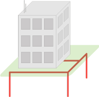
Grounding device - a set of grounding conductor / grounding conductors and grounding conductors (PUE 1.7.19).
This is a device / circuit consisting of a grounding conductor and a grounding conductor connecting this grounding conductor to the grounded part of the network, electrical installation or equipment. It can be distributed, i.e. consist of several mutually remote grounding conductors.
In the figure it is shown by thick red lines:
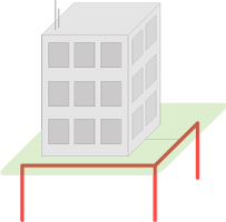
An earthing switch is a conductive part or a set of interconnected conductive parts that are in electrical contact with the ground (PUE 1.7.15).
The conductive part is a metal (conductive) element / electrode of any profile and design (pin, pipe, strip, plate, grid, bucket :-), etc.) located in the ground and through which electric current "flows" into it from the electrical installation.
The configuration of the ground electrode system (number, length, location of the electrodes) depends on the requirements for it, and the ability of the soil to “absorb” electric current coming / “flowing” from the electrical system through these electrodes.
In the figure, it is shown with thick red lines:
Ground resistance - the ratio of the voltage on the grounding device to the current flowing from the ground electrode to the ground (PUE 1.7.26).
Grounding resistance is the main indicator of the grounding device, determining its ability to perform its functions and determining its quality as a whole.
The grounding resistance depends on the area of the electrical contact of the ground electrode (grounding electrodes) with the ground (current “draining”) and the specific electrical resistance of the ground in which this ground electrode is mounted (“absorption” of the current).
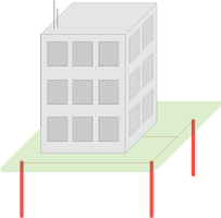
Grounding electrode (ground electrode) - a conductive part in electrical contact with local ground (GOST R 50571.21-2000 p. 3.21)
I repeat: a metal (conductive) element of any profile and structure (pin, pipe, strip, plate, grid, bucket :-), etc.) that is in the ground and through which it “flows” can act as a conductive part electric current from the electrical installation.
In the figure they are shown with thick red lines:
Further definitions that are not found or not described accurately enough in standards and norms, therefore having only my description.
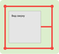
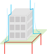
The ground loop is the “popular” name of the ground electrode or grounding device, consisting of several grounding electrodes (groups of electrodes) connected to each other and mounted around the object around its perimeter / circuit.
In the figure, the object is indicated by a gray square in the center,
and the ground loop is indicated by thick red lines:
The electrical resistivity of the soil is a parameter that determines the level of "electrical conductivity" of the soil as a conductor, that is, how well the electric current from the ground electrode will flow in such an environment.
This is a measurable quantity, depending on the composition of the soil, the size and density of
adherence of its particles to each other, humidity and temperature, the concentration of soluble chemicals (salts, acid and alkaline residues) in it.
B. Purpose (types) of grounding
Grounding is divided into two main types according to the role performed - the working (functional) and protective. Also in various sources additional types are given, such as: “instrumental”, “measuring”, “control”, “radio”.B1. Working (functional) grounding
This is the grounding of a point or points of current-carrying parts of an electrical installation, performed to ensure the operation of the electrical installation (not for electrical safety) (PUE 1.7.30).Working grounding (electrical contact with the ground) is used for the normal functioning of the electrical installation or equipment, i.e. for their work in the NORMAL mode.
B2. Protective earth
This is the grounding performed for electrical safety (PUE 1.7.29).Protective grounding protects the electrical installation and equipment, as well as protecting people from the effects of dangerous voltages and currents that can occur during breakdowns, improper operation of equipment (i.e. in EMERGENCY mode) and during lightning discharges.
Protective grounding is also used to protect the equipment from interference during switching in the mains and interface circuits, as well as from electromagnetic interference induced by equipment operating nearby.
In more detail, the protective purpose of grounding can be considered in two examples:
- as part of an external lightning protection system in the form of a grounded lightning rod
- as part of a surge protection system
- as part of the power grid of the facility
B2.1. Grounding in lightning protection
Lightning is a discharge or, in other words, “breakdown”, arising FROM the cloud to the ground, when a critical charge (relative to the ground) is accumulated in the cloud. Examples of this phenomenon on a smaller scale are the “breakdown” ( wiki ) in the capacitor and the gas discharge ( wiki ) in the lamp.
Air is a medium with a very high resistance (dielectric), but the discharge overcomes it, because It has great power. The discharge path passes through areas of least resistance, such as water droplets in the air and trees. This explains the root-like structure of lightning in the air and the frequent hit of lightning in trees and buildings (they have less resistance than air in this gap).
When it hits the roof of a building, lightning continues on its way to the ground, also choosing areas with the least resistance: wet walls, wires, pipes, electrical appliances - thus posing a danger to people and equipment located in this building.
Lightning protection is designed to divert the lightning discharge from the protected building / object. A lightning discharge that goes along the path of least resistance enters a metal lightning rod above the object, then through metal lightning rods located outside the object (for example, on the walls), it goes down to the ground, where it diverges in it (I remind you: the ground is an environment that has the property of “absorbing” ”Electric current).
In order to make lightning protection “attractive” for lightning, as well as to exclude the spread of lightning currents from lightning protection parts (receiver and taps) into an object, it is connected to the ground through an earthing switch having a low grounding resistance.
Grounding in such a system is an indispensable element, because it is it that provides a complete and fast transition of lightning currents to the ground, preventing their distribution throughout the facility.
B2.2. Grounding as part of a surge protection system (SPD)
SPD is designed to protect electronic equipment from the charge accumulated on any part of the line / network as a result of exposure to an electromagnetic field (EMF) induced from a nearby powerful electrical installation (or high-voltage line) or EMF arising from a close (up to hundreds of meters) discharge lightning bolts.
A striking example of this phenomenon is the accumulation of charge on the copper cable of the home network or on the “forward” between buildings during a thunderstorm. At some point, the devices connected to this cable (computer network card or switch port) cannot withstand the “size” of the accumulated charge and an electrical breakdown occurs inside this device, destroying it (simplified).
For "bleeding" the accumulated charge parallel to the "load" on the line in front of the equipment puts an SPD.
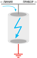
The classic SPD is a gas spark gap ( wiki ), designed for a certain “threshold” of charge, which is less than the “safety margin” of the protected equipment. One of the electrodes of this arrester is grounded, and the other is connected to one of the wires of the line / cable.
Upon reaching this threshold, a discharge occurs inside the arrester :-) between the electrodes. As a result, the accumulated charge is discharged into the ground (via grounding).
As in lightning protection, grounding in such a system is an indispensable element, because it is it that provides a timely and guaranteed occurrence of a discharge in an SPD, preventing the excess of charge on the line above the level safe for the protected equipment.
B2.3. Power Ground
A third example of the protective role of grounding is to ensure the safety of humans and electrical equipment in the event of breakdowns / accidents.Most easily, such a breakdown is described by shorting the phase wire of the power supply network to the device body (short circuit in the power supply unit or short circuit in the water heater through an aqueous medium). A person who touches such a device will create an additional electric circuit through which a current runs, causing damage to internal organs, primarily the nervous system and heart, in the body.
To eliminate such consequences, the connection of the housings with the ground electrode is used (to divert emergency currents to the ground) and protective automatic devices that disconnect the current in a split second in an emergency.
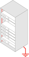
For example, grounding of all cases, cabinets and racks of telecommunication equipment.
B. Grounding quality. Ground resistance
For correct grounding to perform its functions, it must have certain parameters / characteristics. One of the main properties that determine the quality of grounding is the resistance to current spreading (grounding resistance), which determines the ability of the ground electrode (grounding electrodes) to transmit currents that come from the equipment to the ground.This resistance has finite values and, in the ideal case, is a zero value, which means the absence of any resistance when passing “harmful" currents (this guarantees their FULL absorption by the soil).
IN 1. Factors Affecting Grounding Quality
Resistance mainly depends on two conditions:- area (S) of the electrical contact of the ground electrode with ground
- электрическое сопротивление ( R ) самого грунта, в котором находятся электроды
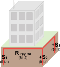
В1.1. Площадь контакта заземлителя с грунтом.
The larger the contact area of the ground electrode system with the ground, the larger the area for the passage of current from this ground electrode to the ground (the more favorable conditions are created for the passage of current into the ground).You can increase the contact area of the ground electrode with ground either by increasing the number of electrodes, connecting them together (by adding together the area of several electrodes), or by increasing the size of the electrodes. When using vertical grounding electrodes, the latter method is very effective if the deep layers of the soil have lower electrical resistance than the upper ones.
B1.2. Electric resistance of soil (specific)
Let me remind you: this is the value that determines how well the soil conducts current through itself. The less resistance the soil has, the more efficient / easier it will be to “absorb” the current from the ground electrode.Examples of highly conductive soils are salt marshes or highly moist clay. The ideal natural environment for transmitting current is seawater.
An example of “bad” grounding is dry sand.
(If interested, you can see the table of soil resistivity values used in the calculation of grounding devices).
Returning to the first factor and the method of reducing the grounding resistance in the form of increasing the electrode depth, we can say that in practice in more than 70% of cases, soil at a depth of more than 5 meters has significantly lower electrical resistivity than that of the surface, due to greater moisture and density . Groundwater is often found which provides the soil with very low resistance. Grounding in such cases is very high quality and reliable.
IN 2. Existing grounding resistance standards
Since it is impossible to achieve the ideal (zero spreading resistance), all electrical equipment and electronic devices are created on the basis of some normalized values of grounding resistance, for example 0.5, 2, 4, 8, 10, 30 and more ohms.For orientation, I will give the following values:
- for a substation with a voltage of 110 kV, the spreading resistance of currents should be no more than 0.5 Ohms (PUE 1.7.90)
- when connecting telecommunication equipment , grounding should usually have a resistance of not more than 2 or 4 ohms
- для уверенного срабатывания газовых разрядников в устройствах защиты воздушных линий связи (например, локальная сеть на основе медного кабеля или радиочастотный кабель) сопротивление заземления, к которому они (разрядники) подключаются должно быть не более 2 Ом. Встречаются экземпляры с требованием в 4 Ом.
- у источника тока (например, трансформаторной подстанции) сопротивление заземления должно быть не более 4 Ом при линейном напряжении 380 В источника трехфазного тока или 220 В источника однофазного тока (ПУЭ 1.7.101)
- у заземления, использующегося для подключения молниеприёмников, сопротивление должно быть не более 10 Ом (РД 34.21.122-87, п. 8)
- для частных домов, с подключением к электросети 220 Вольт / 380 Вольт:
- при использовании системы TN-C-S необходимо иметь локальное заземление с рекомендованным сопротивлением не более 30 Ом (ориентируюсь на ПУЭ 1.7.103)
- при использовании системы TT (изолирование заземления от нейтрали источника тока) и применении устройства защитного отключения (УЗО) с током срабатывания 100 мА необходимо иметь локальное заземление с сопротивлением не более 500 Ом (ПУЭ 1.7.59)
В3. Расчёт сопротивления заземления
For the successful design of a grounding device having the necessary grounding resistance, as a rule, typical grounding configurations and basic calculation formulas are used.The configuration of the ground electrode system is usually chosen by the engineer on the basis of his experience and the possibility of its (configuration) application at a specific object.
The choice of calculation formulas depends on the selected configuration of the ground electrode.
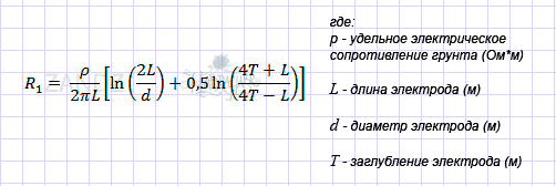
The formulas themselves contain the parameters of this configuration (for example, the number of grounding electrodes, their length, thickness) and the soil parameters of a particular object where the ground electrode will be placed. For example, for a single vertical electrode, this formula will be like this:
The calculation accuracy is usually low and again depends on the soil - in practice, discrepancies in practical results are found in almost 100% of cases. This is due to its (soil) great heterogeneity: it changes not only in depth, but also in area - forming a three-dimensional structure. The available formulas for calculating the grounding parameters can hardly cope with one-dimensional heterogeneity of the soil, and the calculation in a three-dimensional structure is associated with huge computing power and requires extremely high operator training.
In addition, to create an accurate map of the soil, it is necessary to carry out a large amount of geological work (for example, for an area of 10 * 10 meters, you need to make and analyze about 100 pits up to 10 meters long), which causes a significant increase in the cost of the project and most often is not possible.
In the light of the foregoing, almost always calculation is a mandatory, but indicative measure and is usually carried out on the basis of achieving a grounding resistance of "no more than." The formulas are substituted with the average values of the resistivity of the soil, or their largest values. This provides a "margin of safety" and in practice is expressed in obviously lower (lower - means better) values of grounding resistance than expected during design.
Grounding construction
In the construction of grounding conductors, vertical grounding electrodes are most often used. This is due to the fact that it is difficult to deepen horizontal electrodes to a great depth, and with a shallow depth of such electrodes, they greatly increase the grounding resistance (deterioration of the main characteristic) in the winter period due to freezing of the upper soil layer, leading to a large increase in its specific electrical resistance.As the vertical electrodes, steel pipes, pins / rods, angles, etc. are almost always chosen. standard rolling products having a long length (more than 1 meter) with a relatively small transverse dimension. This choice is associated with the possibility of easily deepening such elements into the ground, in contrast, for example, from a flat sheet.
More information about construction - in the following parts.
Continuation:
Alexei Rozhankov, specialist of the technical center " ZANDZ.ru "
In preparing this part, the following materials were used:
- Publications on the site “ Grounding on ZANDZ.ru ”
- Electrical Installation Rules (PUE), part 1.7 as amended by the seventh edition ( google )
- GOST R 50571.21-2000 (IEC 60364-5-548-96)
Grounding devices and electrical potential equalization systems in electrical installations containing information processing equipment ( google ) - Instructions for lightning protection of buildings and structures RD 34.21.122-87 ( google )
- Own experience and knowledge