We use the Nokia 1100 screen for our purposes
Today we will talk about how to use the Nokia 1100 phone screen in our DIY projects, but first we will share a short history about this phone.
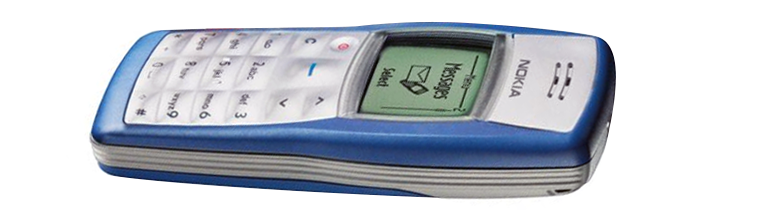
Nokia 1100 - the most popular phone in the world, which was fortunate enough to make us. Since the start of sales in late 2003, the Nokia 1100 has been sold in quantities of over 250 million units - this is not only the best-selling product among phones, but also among all consumer electronics.
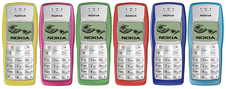
Designed for a wide geography of the audience, the phone had an extremely simple, but satisfying practical design for residents of all continents. Nokia 1100 had a monolithic silicone keyboard and ribbed non-slip edges that protect the phone from damage in humid and dusty climates, as well as a built-in flashlight designed specifically for residents of countries with insufficient street lighting. The appearance of the phone was developed at California-based Nokia Design Center by the Bulgarian-American designer Miki Mehandjiysky.
“The only way to come to all these functions is to spend a lot of time with consumers, communicate with them, and look at how they live. Take, for example, the flashlight function. Most likely you’ll think, “Who needs it at all ?!”, but for consumers, say, from India or Africa, where there is either no electricity at all or it’s not always available, the presence of a flashlight is extremely important ”- Alex Lambik recalls the development of Nokia 1100 (Alex Lambeek), vice president of Nokia, responsible for the budget phone segment.
The Nokia 1100 used an inexpensive monochrome graphic screen with green LED backlighting, providing full readability even in very bright sunshine. The screen resolution was 96x65 pixels, displaying one service and three user lines. Some craftsmen even learned use the Nokia 1100 display for your own purposes, and now we’ll show you how to do it.
The Nokia 1100 used a Philips display with the PCF8814 IC driver, which, despite the I2C protocol support, did not use the latter. Instead, a simple bit exchange mechanism was used.

Nokia 1100 display pinout
To work with the display, you can use almost any microcontroller, for example, PIC, AVR, MSP 430, 8051, but we will resort to a microcontroller based on the PIC 18F458 microchip. We will write the software for the project in pure C in the MPLAB IDE.
The graphic display from Nokia 1100 is made using the controller-mounted technology on COG glass (chip-on-glass) with 9 inputs (the latter is not used) on the rear side. If interested, you can read the description of the controller from the manufacturer. We will discuss several important points necessary for the implementation of our ideas.

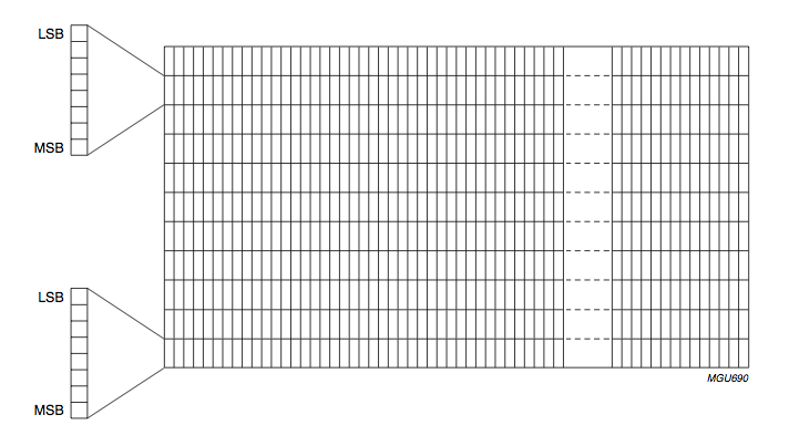
The dimensions of this are 96x65 pixels, which can be accessed directly through RAM-memory, as shown in the image below:
A typical RAM example is shown below. The vertical axis displays cells from 0 to 8 with eight bits for each address when combined with the horizontal axis. The horizontal axis displays the addressing from 0 to 95, and each bit is responsible for the corresponding pixel along the X axis.
This display has two addressing modes: horizontal and vertical.

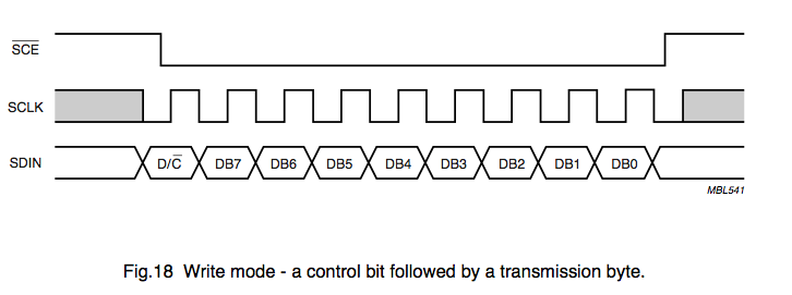


Bits are sent to the LCD as follows:
Cleaning the display : after initialization, set SCE to Ground to turn on the display. Set D / C to High to send data to the display. Repeat the “write byte 0x00” operation to write to the display 864 times to clear all pixels.
The circuit is very simple to understand, but keep in mind that connecting wires to the display is not a trivial task, and you cannot supply more than 3V. Applying more voltage may render your display unusable. Our prototype is shown below.

The software is written in C using MPLAB and the Microchip C18 compiler. Source codes and already compiled firmware are available at the link .
That's it, now you can use the Nokia 1100 screen for your own purposes. True, you will have to disassemble one of the most shock-resistant phones in history without our prompts.
Nokia 1100 - the most popular phone in the world, which was fortunate enough to make us. Since the start of sales in late 2003, the Nokia 1100 has been sold in quantities of over 250 million units - this is not only the best-selling product among phones, but also among all consumer electronics.
Designed for a wide geography of the audience, the phone had an extremely simple, but satisfying practical design for residents of all continents. Nokia 1100 had a monolithic silicone keyboard and ribbed non-slip edges that protect the phone from damage in humid and dusty climates, as well as a built-in flashlight designed specifically for residents of countries with insufficient street lighting. The appearance of the phone was developed at California-based Nokia Design Center by the Bulgarian-American designer Miki Mehandjiysky.
“The only way to come to all these functions is to spend a lot of time with consumers, communicate with them, and look at how they live. Take, for example, the flashlight function. Most likely you’ll think, “Who needs it at all ?!”, but for consumers, say, from India or Africa, where there is either no electricity at all or it’s not always available, the presence of a flashlight is extremely important ”- Alex Lambik recalls the development of Nokia 1100 (Alex Lambeek), vice president of Nokia, responsible for the budget phone segment.
The Nokia 1100 used an inexpensive monochrome graphic screen with green LED backlighting, providing full readability even in very bright sunshine. The screen resolution was 96x65 pixels, displaying one service and three user lines. Some craftsmen even learned use the Nokia 1100 display for your own purposes, and now we’ll show you how to do it.
We disassemble and use
The Nokia 1100 used a Philips display with the PCF8814 IC driver, which, despite the I2C protocol support, did not use the latter. Instead, a simple bit exchange mechanism was used.
Nokia 1100 display pinout
To work with the display, you can use almost any microcontroller, for example, PIC, AVR, MSP 430, 8051, but we will resort to a microcontroller based on the PIC 18F458 microchip. We will write the software for the project in pure C in the MPLAB IDE.
About screen
The graphic display from Nokia 1100 is made using the controller-mounted technology on COG glass (chip-on-glass) with 9 inputs (the latter is not used) on the rear side. If interested, you can read the description of the controller from the manufacturer. We will discuss several important points necessary for the implementation of our ideas.
The dimensions of this are 96x65 pixels, which can be accessed directly through RAM-memory, as shown in the image below:
A typical RAM example is shown below. The vertical axis displays cells from 0 to 8 with eight bits for each address when combined with the horizontal axis. The horizontal axis displays the addressing from 0 to 95, and each bit is responsible for the corresponding pixel along the X axis.
Addressing Modes
This display has two addressing modes: horizontal and vertical.
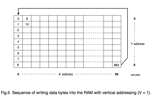
Vertical addressing mode
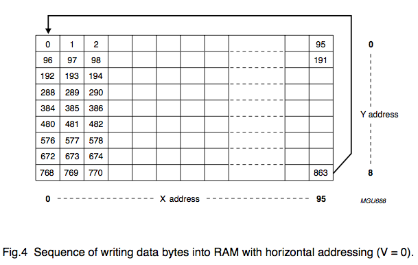
In the vertical addressing mode, each write instruction will increment the address in the Y direction, then returning to the starting address.Horizontal addressing mode
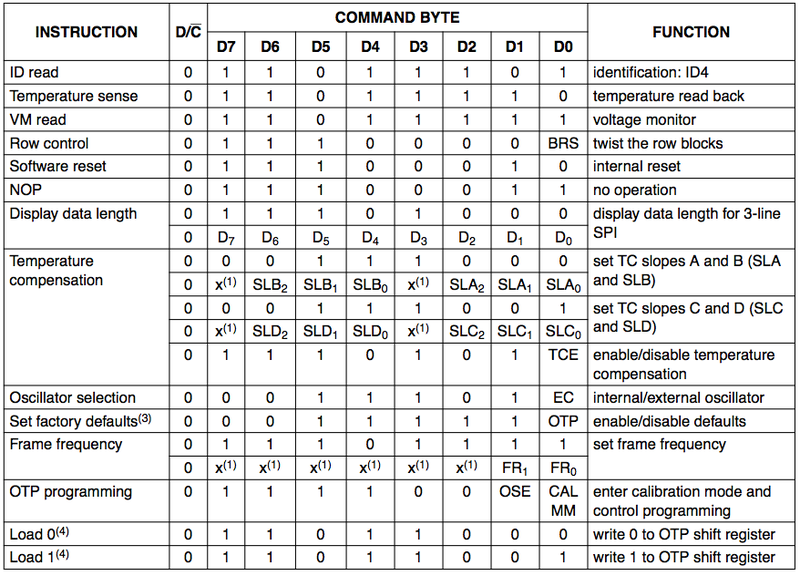
Each instruction will increment the address in the X direction and then return to the starting address.PCF8814 Instruction Set
Serial communication
Bits are sent to the LCD as follows:
- Install SC to GND
- Install SCLK in GND
- Send D / C bit (data or command) to SDA
- Set SCLK to 1
- Set SCLK to 0
- Send data bit to SDA
- Set SCLK to 1
- Repeat steps 5.6 and 7 for the remaining seven bits.
Display Initialization Sequence
- Set CS to Ground to activate the display.
- Set RST to Low
- Wait some time ~ 5ms.
- Set RST to high.
- Write the 0x20 command to the LCD on the serial bus. Write Vop Register
- Write the 0x90 command to the LCD on the serial bus.
- Write the 0xA4 command to the LCD on the serial bus. Set the display to normal mode
- Write the 0x2F command to the LCD on the serial bus. Power Management (enable / disable charge pump)
- Write the 0x40 command to the LCD on the serial bus. Set starting line address = 0
- Write the 0xB0 command to the LCD on the serial bus. Set the address along the axis Y = 0
- Write the 0x10 command to the LCD on the serial bus. Set the address on the X axis, the lower 3 bits
- Write the 0x00 command to the LCD on the serial bus. Set address on X axis, high 3 bits
- Write the 0xC8 command to the LCD on the serial bus. Flip Y axis (relative to the X axis)
- Write the 0xA1 command to the LCD on the serial bus. Invert screen in horizontal axis
- Write the 0xAC command to the LCD on the serial bus. Set the initial row (R0) of the display
- Write the 0x07 command to the LCD on the serial bus.
- Write the 0xF9 command to the LCD on the serial bus.
- Write the 0xAF command to the LCD on the serial bus. Turn on / off display
- Clear display
- Write the 0xA7 command to the LCD on the serial bus. Invert display
- Wait approximately 500 ms
- Write the 0xA7 command to the LCD on the serial bus. Return display to normal
Cleaning the display : after initialization, set SCE to Ground to turn on the display. Set D / C to High to send data to the display. Repeat the “write byte 0x00” operation to write to the display 864 times to clear all pixels.
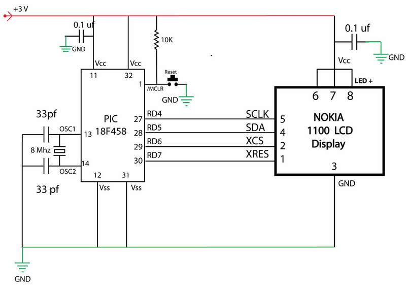
Putting together a circuit
The circuit is very simple to understand, but keep in mind that connecting wires to the display is not a trivial task, and you cannot supply more than 3V. Applying more voltage may render your display unusable. Our prototype is shown below.
Software
The software is written in C using MPLAB and the Microchip C18 compiler. Source codes and already compiled firmware are available at the link .
That's it, now you can use the Nokia 1100 screen for your own purposes. True, you will have to disassemble one of the most shock-resistant phones in history without our prompts.