Using Inhaos RF-2400 Radio Modules
An article about radio modules was recently published on a hub ; in my opinion, it is unfairly deprived of attention of 2.4 GHz devices with SPI interface in it. They attract at the price of two or three bucks apiece, and with a ready-made communication protocol, including addressing, CRC, sending confirmation and other amenities.
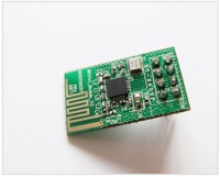
Modules RF-2400R from Inhaos built on the chip BK2421 , which seems pinched from Nordic NRF24L01 . Therefore, to work with them, you can use the Mirf library , written under Nordic.
The problem that I solved was to organize the exchange of data between several modules, so the logic of work used in Mirf and built on the interaction between a pair of modules was not very convenient. Instead, a virtual piece of memory was organized, synchronized via the radio interface, which was used by several devices simultaneously. The result is such a library for arduino.
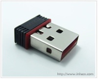
In addition to the RF-2400P modules, Inhaos offers a very nice USB “whistle” RF-2410U built on the same BK2421 but already in conjunction with the C8051F321 microcontroller , which comes with a stitched bootloader and can be programmed via USB using the supplied bootloader.
In my opinion, it turns out a very affordable and interesting solution for a system such as “smart home” - a bunch of cheap radio modules that, thanks to the price, can even be integrated into light bulbs and a compact control interface in the form of a “whistle” that can be plugged into any computer without bothering with additional wires and serial port availability.
To simplify the process of getting to know these devices and illustrate their joint work, the following demo is presented to your attention.
In principle, one can do without (1) or (3).
1. Connect the RF-2400P modules to the Arduino boards as follows:
2. Copy the library code to the arduino folder and flash the client and server scripts.
3. We observe the exchange of data through a serial interface.
4. Download the firmware to the RF-2410U.
5. When connected, the RF-2410U will ask for the driver, give them to him .
6. It remains to download the client application, press the start button and observe the synchronization process in real time.
Modules RF-2400R from Inhaos built on the chip BK2421 , which seems pinched from Nordic NRF24L01 . Therefore, to work with them, you can use the Mirf library , written under Nordic.
The problem that I solved was to organize the exchange of data between several modules, so the logic of work used in Mirf and built on the interaction between a pair of modules was not very convenient. Instead, a virtual piece of memory was organized, synchronized via the radio interface, which was used by several devices simultaneously. The result is such a library for arduino.
In addition to the RF-2400P modules, Inhaos offers a very nice USB “whistle” RF-2410U built on the same BK2421 but already in conjunction with the C8051F321 microcontroller , which comes with a stitched bootloader and can be programmed via USB using the supplied bootloader.
In my opinion, it turns out a very affordable and interesting solution for a system such as “smart home” - a bunch of cheap radio modules that, thanks to the price, can even be integrated into light bulbs and a compact control interface in the form of a “whistle” that can be plugged into any computer without bothering with additional wires and serial port availability.
RF- 2400 Demo
To simplify the process of getting to know these devices and illustrate their joint work, the following demo is presented to your attention.
Iron
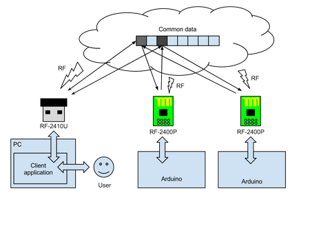
- Client device - Arduino + RF-2400P
- Server Device - Arduino + RF-2400P
- Observer - Windows PC + RF-2410U
In principle, one can do without (1) or (3).
Software
- RFSync library and arduino scripts for client and server parts.
- Firmware for RF-2410U, and drivers for it.
- Windows client application RF-2410U.
Work logic
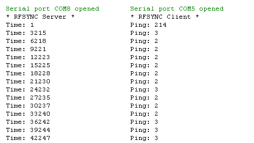
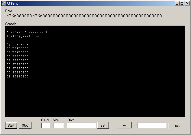
- On the client ardun board, the current time is written to the synchronized array at address 0.
- On the server board, after synchronization, the data read but at address 0 are duplicated at address 5.
- After synchronization is completed, the value at address 5 is read on the client board and calculated, the time spent on synchronization.
- All this
circussynchronization process is observed on a Windows machine with a connected RF-2410U module using a client application.
Launch
1. Connect the RF-2400P modules to the Arduino boards as follows:
| Module | Arduino |
|---|---|
| Miso | 12 |
| MOSI | eleven |
| SCK | thirteen |
| CE | 8 |
| CSN | 7 |
| 3.3 V | 3.3 V |
| GND | GND |
2. Copy the library code to the arduino folder and flash the client and server scripts.
3. We observe the exchange of data through a serial interface.
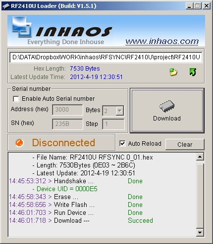
4. Download the firmware to the RF-2410U.
- make sure the module is not connected to the computer
- run the firmware application .
- select firmware, click “Download”
- insert the RF-2410U module into the USB port
- wait for the message Download Succeed
5. When connected, the RF-2410U will ask for the driver, give them to him .
6. It remains to download the client application, press the start button and observe the synchronization process in real time.