Plesiochronous Digital Hierarchy and E1 Stream
Greetings, friends!
In the course of studying Digital transmission systems, as well as on the recommendation of a mentor, in order to better understand the material being studied and put everything on the shelves, I will try to explain this material to you, if I succeed, then we can assume that I learned it well. I hope you will be interested.
In the article I will tell briefly about the DSP and the features of their construction, PDI (PDH) and in more detail about the flow of E1 and its structure.
It will not be news to anyone that the main trend in the development of telecommunications around the world is the digitalization of communication networks, which provides for the construction of a network based on digital transmission and switching methods. This is due to the following significant advantages of digital transmission methods over analog:
High noise immunity.
The requirements for DSPs are defined in the ITU-T G-series recommendations, and this recommendation also presents two types of DSP hierarchies: plesiochronous digital hierarchy (PDI) and synchronous digital hierarchy (SDH). The primary signal for all types of DSPs is a digital stream with a transmission speed of 64 Kbps, called the main digital channel (BCC) [foreign sources: Basic Digital Circuit (BDC)] , on Habré it was already told how digitization of channels of HF occurs in this article . The principle of time division of channels (WRC) [foreign sources: Time Division Multiply Access (TDMA), or Time Division Multiplexing (TDM)] is used to combine the BCC signals into group high-speed digital signals .
The historically first plesiochronous digital hierarchy (PDI) [foreign sources: Plesiochronous Digital Hierarchy (PDH)], which has emerged historically, has European, North American, and Japanese varieties.
For digital flows of PDI, the corresponding notation is used, for North American - T, Japanese - J (DS), European - E. Digital streams of the first level are designated T1, E1, J1 of the second T2, E2, J2, etc. ...
To use on the communication networks of the Russian Federation adopted the European PDI.
On the communication network of the Russian Federation, DSPPs of domestic and foreign production are operated. Domestic systems are called DSP with PCM (digital transmission systems with pulse-code modulation). Instead of the hierarchy level, the system designation indicates the number of informational BCCs of the system. So, the DSP of the first level of the hierarchy is designated as IKM-30, the second - as IKM-120, etc.
In the plesiochronous, “as if synchronous”, DSPs, the principle of SQF is used, therefore, correct restoration of the initial signals at reception is possible only with synchronous and common mode operation of the generator equipment at the transmitting and receiving stations. For the normal operation of plesiochronous DSPs, the following types of synchronization must be provided:
Clock synchronization ensures equality in the processing speeds of digital signals in linear and station regenerators, codecs, and other DSP devices that process the signal with a clock frequency of Ft.
There are several options for clock synchronization:
Cycle synchronization is as follows. At the transmitting station, a digital clock signal (CC) is introduced into the group digital signal at the beginning of the cycle. At the receiving station, a clock receiver (MSS) is installed, which extracts the cyclic clock signal from the group digital signal and thereby determines the beginning of the transmission cycle.
There are 3 types of flow E1:
Consider the structure of the transmission frame DSP IKM-30.
The structure of the E1 stream is defined in ITU-T G.704. This stream is called the primary digital stream and is organized by the union of 30 information BCC.
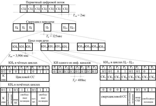
The linear signal of the system is built on the basis of supercycles, cycles, channel and clock intervals, as shown in the figure above (the designation 0/1 corresponds to the transmission of a random signal in a given clock interval). A transmission super cycle (SC) corresponds to the minimum time interval for which one count of each of the 60 signal channels (SC) and alarm transmission channels (loss of super-cycle or cycle synchronization) is transmitted. The duration of the SC TSC = 2ms. The supercycle consists of 16 transmission cycles (from Ts0 to Ts15). The cycle time is TC = 125 μs and corresponds to the sampling interval of the PM channel with a frequency of 8 kHz. Each cycle is divided into 32 channel intervals (time slots) with a duration of Tk = 3.906 μs. Channel intervals KI1-KI15, KI17-KI31 are reserved for the transmission of information signals. KI0 and KI16 - for the transmission of official information. Each channel interval consists of eight discharge intervals (P1-P8) with a duration of Tr = 488ns. Half of the discharge interval can be occupied by a rectangular pulse with a duration of Ti = 244ns when transmitting a unit in this discharge (when transmitting zero, there is no pulse in the discharge interval). Intervals KI0 in even cycles are intended to transmit a cyclic clock signal (DSS), having the form 0011011 and occupying the intervals P2 - P8. In the interval P1 of all cycles, information of a permanent data transmission channel (DI) is transmitted. In odd cycles, the intervals P3 and P6 KI0 are used to transmit information about the loss of cyclic synchronization (Avar. ЦС - LOF) and the reduction of the residual attenuation of the channels to a value at which self-excitation can occur in them (Remain.). The intervals P4, P5, P7 and P8 are free, they are occupied by single signals to improve the operation of the clock isolators. In the interval KI16 of the zero cycle (Ts0), a super-cycle clock signal of the form 0000 (P1 - P4) is transmitted, as well as a signal about the loss of super-cycle synchronization (P6 - Avar. STsS - LOM). The remaining three bit intervals are free. In the KI16 channel interval of the remaining cycles (Ts1 - Ts15), the service channels SK1 and SK2 are transmitted; moreover, SK1 for the 1st and 16th channels of the PM are transmitted to Ts1, in Ts2 - for the 2nd and 17th, etc. . The intervals P3, P4, P6 and P7 are free. From the point of view of telephone channel transmission: the telephone channel is an 8-bit count. The payload is a conversation between two subscribers. In addition, service information is transmitted (dialing, hang up, etc.) - control and interaction signals (SUV). To transmit such signals, it is enough to repeat them once every 15 cycles, in this case, each SUV will occupy 4 bits (SUV for a particular channel). For these purposes, the 16th channel interval was selected. In one channel are placed SUV for two telephone channels. Because only 30 channels, one channel uses two channels, then the cycle needs to be repeated 15 times, therefore, from Ts1 to Ts15 we transmit all the information about the SUV. Thus, it is necessary to determine the cycle number. For these purposes, the zero cycle contains a supercycle SS (“0000” in 1 four bytes –MFAS). In the 6th bit, super cycle loss (LOM) is transmitted. from Ts1 to Ts15 we transmit all the information about the SUV. Thus, it is necessary to determine the cycle number. For these purposes, the zero cycle contains a supercycle SS (“0000” in 1 four bytes –MFAS). In the 6th bit, super cycle loss (LOM) is transmitted. from Ts1 to Ts15 we transmit all the information about the SUV. Thus, it is necessary to determine the cycle number. For these purposes, the zero cycle contains a supercycle SS (“0000” in 1 four bytes –MFAS). In the 6th bit, super cycle loss (LOM) is transmitted.
I had to come across people who, trying to explain the structure of the E1 stream, presented it as a pipe, into which 32 smaller pipes (32 timeslots) were crammed, this is pretty obvious, but absolutely not right, because in PDI, data is transmitted sequentially, bit by bit, and not in parallel.
To control transmission errors, the first bit of the zero channel interval is used.
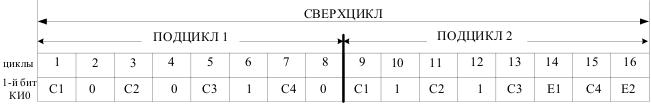
The contents of the first bit KI0 in various subcycles.
The polynomial x4 + x + 1 determines the presence of an error. Bits C1, C2, C3, C4 is the remainder of dividing the subcycle (8 cycles) by the polynomial x4 + x + 1. In this case, the result is inserted into the next subcycle. We take the value of the 1st sub-cycle, compare it with the 2nd-m. If there is a mismatch, an error message is issued. Bits E1 and E2 are designed to transmit error messages to the transmitter side on the first and second cycle (E1 - for the first, E2 - for the second). For correct processing in even cycles (except 14 and 16), a super-cycle clock signal (001011) is introduced to control errors.
The physical layer includes a description of the electrical parameters of the interfaces and the parameters of the transmission signals, including the structure of the linear code. These parameters are described in ITU-T Recommendation G.703.
The following physical interfaces are defined for PDI:
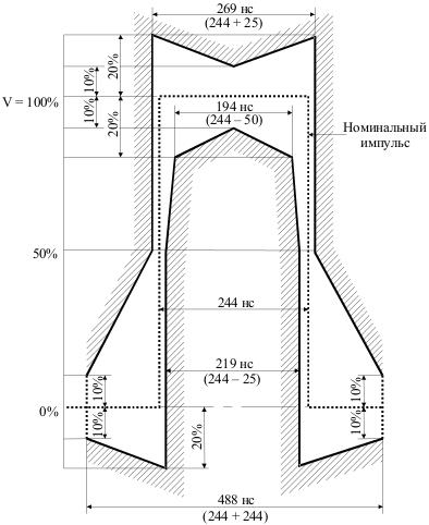
The pulse mask of the physical interface of the 2048 Kbps stream.
On this, I think you can stop. Thank you all for your attention, I hope you were interested.Subscribe, like ... In the article I tried to present as much information as possible in the simplest possible way (I don’t know if I was able to) without diving too deep into the details of the DSP structures and, in particular, the E1 stream.
If I like the article, I can try to write the same about the synchronous digital hierarchy (SDH) [foreign sources: Synchronous Digital Hierarchy (SDH)] and synchronous transport module (STM)[Foreign sources: Synchronous Transport Module (STM)] - STM-1.
Technologies for measuring the primary network - I.G. Cormorants;
Modern high-speed digital telecommunication systems - V.N. Gordienko.
UPD: Slightly supplemented the article with English terms and abbreviations.
In the course of studying Digital transmission systems, as well as on the recommendation of a mentor, in order to better understand the material being studied and put everything on the shelves, I will try to explain this material to you, if I succeed, then we can assume that I learned it well. I hope you will be interested.
In the article I will tell briefly about the DSP and the features of their construction, PDI (PDH) and in more detail about the flow of E1 and its structure.
Digital Transmission Systems
Features of the construction of digital transmission systems
It will not be news to anyone that the main trend in the development of telecommunications around the world is the digitalization of communication networks, which provides for the construction of a network based on digital transmission and switching methods. This is due to the following significant advantages of digital transmission methods over analog:
High noise immunity.
- Weak dependence of the transmission quality on the length of the communication line.
- The stability of the parameters of the DSP channels.
- The efficiency of using channel bandwidth for transmitting discrete signals.
- Ability to build a digital communication network.
- High technical and economic indicators.
The requirements for DSPs are defined in the ITU-T G-series recommendations, and this recommendation also presents two types of DSP hierarchies: plesiochronous digital hierarchy (PDI) and synchronous digital hierarchy (SDH). The primary signal for all types of DSPs is a digital stream with a transmission speed of 64 Kbps, called the main digital channel (BCC) [foreign sources: Basic Digital Circuit (BDC)] , on Habré it was already told how digitization of channels of HF occurs in this article . The principle of time division of channels (WRC) [foreign sources: Time Division Multiply Access (TDMA), or Time Division Multiplexing (TDM)] is used to combine the BCC signals into group high-speed digital signals .
Plesiochronous Digital Hierarchy
The historically first plesiochronous digital hierarchy (PDI) [foreign sources: Plesiochronous Digital Hierarchy (PDH)], which has emerged historically, has European, North American, and Japanese varieties.
| Hierarchy level | Europe | North America | Japan | |||
| Mbps speed | Coeff. Multiplex. | Mbps speed | Coeff. Multiplex. | Mbps speed | Coeff. Multiplex. | |
| 0 | 0,064 | - | 0,064 | - | 0,064 | - |
| 1 | 2,048 | thirty | 1,554 | 24 | 1,554 | 24 |
| 2 | 8,448 | 4 | 6,312 | 4 | 6,312 | 4 |
| 3 | 34,368 | 4 | 44,736 | 7 | 32,064 | 5 |
| 4 | 139,264 | 4 | - | - | 97,728 | 3 |
For digital flows of PDI, the corresponding notation is used, for North American - T, Japanese - J (DS), European - E. Digital streams of the first level are designated T1, E1, J1 of the second T2, E2, J2, etc. ...
To use on the communication networks of the Russian Federation adopted the European PDI.
On the communication network of the Russian Federation, DSPPs of domestic and foreign production are operated. Domestic systems are called DSP with PCM (digital transmission systems with pulse-code modulation). Instead of the hierarchy level, the system designation indicates the number of informational BCCs of the system. So, the DSP of the first level of the hierarchy is designated as IKM-30, the second - as IKM-120, etc.
Basic principles of synchronization
In the plesiochronous, “as if synchronous”, DSPs, the principle of SQF is used, therefore, correct restoration of the initial signals at reception is possible only with synchronous and common mode operation of the generator equipment at the transmitting and receiving stations. For the normal operation of plesiochronous DSPs, the following types of synchronization must be provided:
Clock synchronization ensures equality in the processing speeds of digital signals in linear and station regenerators, codecs, and other DSP devices that process the signal with a clock frequency of Ft.
There are several options for clock synchronization:
- Co-directional interface: additional clock transmission is carried out on separate lines;
- Anti-directional interface: one unit (controlling) sets another (subordinate) operating clock frequency;
- Interface with a centralized master (master oscillator): the master oscillator performs clocking of all equipment nodes.
Cycle synchronization is as follows. At the transmitting station, a digital clock signal (CC) is introduced into the group digital signal at the beginning of the cycle. At the receiving station, a clock receiver (MSS) is installed, which extracts the cyclic clock signal from the group digital signal and thereby determines the beginning of the transmission cycle.
Stream E1
The structure of the stream E1.
There are 3 types of flow E1:
- Unstructured (there is no division into KI channel intervals [foreign sources: Time Slot] , the logical structure is not allocated; data stream at a speed of 2048Kbit / s); used when transmitting data;
- Flow with a cyclic structure (channel intervals are allocated, but control and interaction signals (SUV) are not transmitted) - PCM-31;
- A stream with a super-cycle structure (both cyclic and super-cycle structures are distinguished) - PCM-30.
Consider the structure of the transmission frame DSP IKM-30.
The structure of the E1 stream is defined in ITU-T G.704. This stream is called the primary digital stream and is organized by the union of 30 information BCC.
The linear signal of the system is built on the basis of supercycles, cycles, channel and clock intervals, as shown in the figure above (the designation 0/1 corresponds to the transmission of a random signal in a given clock interval). A transmission super cycle (SC) corresponds to the minimum time interval for which one count of each of the 60 signal channels (SC) and alarm transmission channels (loss of super-cycle or cycle synchronization) is transmitted. The duration of the SC TSC = 2ms. The supercycle consists of 16 transmission cycles (from Ts0 to Ts15). The cycle time is TC = 125 μs and corresponds to the sampling interval of the PM channel with a frequency of 8 kHz. Each cycle is divided into 32 channel intervals (time slots) with a duration of Tk = 3.906 μs. Channel intervals KI1-KI15, KI17-KI31 are reserved for the transmission of information signals. KI0 and KI16 - for the transmission of official information. Each channel interval consists of eight discharge intervals (P1-P8) with a duration of Tr = 488ns. Half of the discharge interval can be occupied by a rectangular pulse with a duration of Ti = 244ns when transmitting a unit in this discharge (when transmitting zero, there is no pulse in the discharge interval). Intervals KI0 in even cycles are intended to transmit a cyclic clock signal (DSS), having the form 0011011 and occupying the intervals P2 - P8. In the interval P1 of all cycles, information of a permanent data transmission channel (DI) is transmitted. In odd cycles, the intervals P3 and P6 KI0 are used to transmit information about the loss of cyclic synchronization (Avar. ЦС - LOF) and the reduction of the residual attenuation of the channels to a value at which self-excitation can occur in them (Remain.). The intervals P4, P5, P7 and P8 are free, they are occupied by single signals to improve the operation of the clock isolators. In the interval KI16 of the zero cycle (Ts0), a super-cycle clock signal of the form 0000 (P1 - P4) is transmitted, as well as a signal about the loss of super-cycle synchronization (P6 - Avar. STsS - LOM). The remaining three bit intervals are free. In the KI16 channel interval of the remaining cycles (Ts1 - Ts15), the service channels SK1 and SK2 are transmitted; moreover, SK1 for the 1st and 16th channels of the PM are transmitted to Ts1, in Ts2 - for the 2nd and 17th, etc. . The intervals P3, P4, P6 and P7 are free. From the point of view of telephone channel transmission: the telephone channel is an 8-bit count. The payload is a conversation between two subscribers. In addition, service information is transmitted (dialing, hang up, etc.) - control and interaction signals (SUV). To transmit such signals, it is enough to repeat them once every 15 cycles, in this case, each SUV will occupy 4 bits (SUV for a particular channel). For these purposes, the 16th channel interval was selected. In one channel are placed SUV for two telephone channels. Because only 30 channels, one channel uses two channels, then the cycle needs to be repeated 15 times, therefore, from Ts1 to Ts15 we transmit all the information about the SUV. Thus, it is necessary to determine the cycle number. For these purposes, the zero cycle contains a supercycle SS (“0000” in 1 four bytes –MFAS). In the 6th bit, super cycle loss (LOM) is transmitted. from Ts1 to Ts15 we transmit all the information about the SUV. Thus, it is necessary to determine the cycle number. For these purposes, the zero cycle contains a supercycle SS (“0000” in 1 four bytes –MFAS). In the 6th bit, super cycle loss (LOM) is transmitted. from Ts1 to Ts15 we transmit all the information about the SUV. Thus, it is necessary to determine the cycle number. For these purposes, the zero cycle contains a supercycle SS (“0000” in 1 four bytes –MFAS). In the 6th bit, super cycle loss (LOM) is transmitted.
I had to come across people who, trying to explain the structure of the E1 stream, presented it as a pipe, into which 32 smaller pipes (32 timeslots) were crammed, this is pretty obvious, but absolutely not right, because in PDI, data is transmitted sequentially, bit by bit, and not in parallel.
Transmission Error Control
To control transmission errors, the first bit of the zero channel interval is used.
The contents of the first bit KI0 in various subcycles.
The polynomial x4 + x + 1 determines the presence of an error. Bits C1, C2, C3, C4 is the remainder of dividing the subcycle (8 cycles) by the polynomial x4 + x + 1. In this case, the result is inserted into the next subcycle. We take the value of the 1st sub-cycle, compare it with the 2nd-m. If there is a mismatch, an error message is issued. Bits E1 and E2 are designed to transmit error messages to the transmitter side on the first and second cycle (E1 - for the first, E2 - for the second). For correct processing in even cycles (except 14 and 16), a super-cycle clock signal (001011) is introduced to control errors.
Physical layer OSI model in PDI
The physical layer includes a description of the electrical parameters of the interfaces and the parameters of the transmission signals, including the structure of the linear code. These parameters are described in ITU-T Recommendation G.703.
The following physical interfaces are defined for PDI:
- E0 - symmetrical pair (120 Ohms);
- E1 - coaxial cable (75 Ohms) or balanced pair (120 Ohms);
- E2, E3, E4 - coaxial cable (75 Ohm).
- E0 - AMI;
- E1, E2, E3 - HDB3;
- E4 - CMI.
The pulse mask of the physical interface of the 2048 Kbps stream.
On this, I think you can stop. Thank you all for your attention, I hope you were interested.
If I like the article, I can try to write the same about the synchronous digital hierarchy (SDH) [foreign sources: Synchronous Digital Hierarchy (SDH)] and synchronous transport module (STM)[Foreign sources: Synchronous Transport Module (STM)] - STM-1.
Literature
Technologies for measuring the primary network - I.G. Cormorants;
Modern high-speed digital telecommunication systems - V.N. Gordienko.
UPD: Slightly supplemented the article with English terms and abbreviations.