Simple automation: Easy programmable relays
Hello dear community!
On Habré a lot of words have already been said about various automation devices, ranging from simple Arduino to industrial multiprocessor systems. I want to paint another white spot on the habro-automation card with an article on intermediate devices - programmable relays , using the example of Easy microprocessor devices manufactured by Eaton (Moeller) Corporation.
Quite a lot of time has passed since my first acquaintance with this type of device, but still, these “electronic kids” remain indispensable assistants for the implementation of a wide range of engineering and domestic tasks.
A programmable (intelligent) relay is a type of programmable logic controller (PLC).
Programmable relays have found the main application as means of automation of local circuits, individual units of machines and mechanisms, for domestic use.
On the basis of smart relays, various automatic control systems are intuitively and clearly built, for example, control systems for pumping equipment, drilling machines, automatic reserve input systems (ATS). The compact size and ease of programming make it possible to develop elements of the “smart home” system based on programmable relays.
The standard means of describing and constructing programs for these devices are the languages of relay logic ( LD ) or function blocks ( FBD), designed specifically for engineers engaged in the automation of industry and production.
The simplicity of the programming language, the ease of transition from obsolete automation systems based on relay-contactor circuits to microprocessor devices, allowed programmable relays to take a reliable position in the market of automation devices.
Based on the name of the described class of devices, the main element to be operated will be a relay.
Relay - an electromechanical device designed to switch electrical circuits for a given change in electrical or non-electrical input values. A classic relay has a control coil x , and a group of contacts that implement the output function y = f (x) .
When a control voltage is applied to the input of the coil, the contacts change their initial state to inverse.
A contact group can contain two main types of contacts: normally open contacts and normally closed contacts .
Normally open contact - a contact that is in the open state in the absence of voltage on the control coil.
Normally closed contact - a contact that is in a closed state in the absence of voltage on the control coil.
Thus, two main types of functions implemented using relays can be written:
y (x) = x - for normally open contacts;
y (x) = x̅ - for normally closed contacts.
The remaining types of functions implemented using relays are based on giving the contact group additional properties. The functions and types of relay contacts are shown in the figure below.
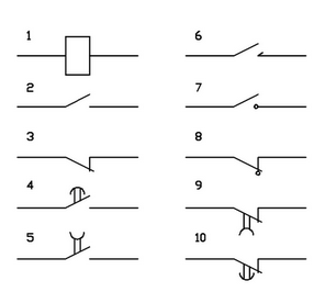
1 - relay coil (control circuit), 2 - normally open contact, 3 - normally closed contact, 4 - normally open contact with the moderator upon operation, 5 - normally open contact with the moderator upon return, 6 - normally open pulse contact, 7 - normally open contact without self-resetting, 8 - normally closed contact without self-resetting, 9 - normally closed contact with moderator when triggered, 10 - normally closed contact with moderator when returning.
A discrete automated device is understood to mean a control device that processes a priori and current information into control information, and the carriers of all these components of information are signals that are discrete in level and in time. This means that the signal state of each input (output) of the automated device is characterized by two levels: the minimum, conditionally designated “0”, and the maximum, designated “1”.
Drawing up a control block diagram for the given conditions of its operation is called synthesis . Determining the working conditions of a circuit or its individual elements by the existing structure is called an analysis of control circuits.
Circuits on relay and contactless elements can be composed in two ways.
The first method is experimental, widely used in the practice of logical design of relay-contactor circuits. Based on the given operating conditions of the individual parts of the working machine, a circuit diagram of the automation system is made up. Contactless analogs of relay-contact circuits, in which the specified operating conditions of the circuit are expressed in the form of functions of the algebra of logic, are composed similarly . At the same time, it is advisable to minimize any contact or contactless circuit constructed in such an experimental way. Minimization of circuits is based on the laws of algebra of logic.
Second wayThe construction (synthesis) of circuits is based on a more complete use of the theory of algebra of logic and the principles of formalizing the real working conditions of the automation circuit. In this case, they proceed from the given operating conditions, compiling the corresponding state tables (function maps), where combinations of arguments and values of functions (output signals) are noted in the form of logical “1” and “0”. The main task of the synthesis is to determine this form of expression of the desired logical function, which can be implemented using the minimum number of possibly simplest elements. The synthesis of relay control circuits is reduced to the preparation of a structural formula (analytical expression) that describes the logical functions that must be performed by this device. Then, the resulting algebraic formula is analyzed and a graphic outline of the circuit is made.
The analysis of the full course of the theory of logic and synthesis of circuits is beyond the scope of this article; all those interested in this topic can familiarize themselves with the subject in detail using references to the literature (at the end of the article).
Let's look at the process of creating a control circuit using a simple example from life.
It is necessary to develop a lighting control system for the office space in accordance with the following conditions:
Given an
office space with one main lighting group (fluorescent lamps) and one group of emergency and background lighting.
Electric blinds.
Necessary
Additional terms
Let us first of all determine the correspondence of the input and output signals of the designed system to variables. We agree to denote all input signals by the variables I with resp. index, and all output signals - variables Q with resp. index.
Input variables :
I1 - light sensor signal.
I2 - signal of the upper position of the blinds.
I3 - signal for the lower position of the blinds.
I4 - background light enable signal.
Output variables :
Q1 - turn on / off the main lighting group.
Q2 - turn on / off the emergency lighting.
Q3 - turn on / off the background lighting.
Q4 - raising the blinds.
Q5 - lowering the blinds.
Time variables :
T1 - reaching the end time of the working day.
T2 - reaching the start time of the working day.
Next, we divide our problem into conditional parts and compose logical functions for each of the parts.
So, we got logical functions that describe the behavior of the elements of our system depending on the conditions and disturbing influences. Next, it is necessary to make the transition to a relay-contactor circuit, i.e., describe the operation of our system on real physical devices.
The transition from the functions of the algebra of logic to the relay-contactor circuit is very simple. To do this, it is enough to represent all the input and intermediate variables in the form of relay contacts, and the output functions in the form of relay coils.
A separate word needs to be said about time-dependent variables. In our example, these are variables describing the time interval of the working day, T1 and T2. There are special types of relays — time relays and timers — to represent time-dependent variables .
To go to the practical part of our task, we need to figure out which hardware is more profitable and convenient to carry out the solution. Manufacturers represent a fairly wide range of programmable relays for optimal cost and functionality solutions for certain types of engineering problems. Let's try to understand this variety.
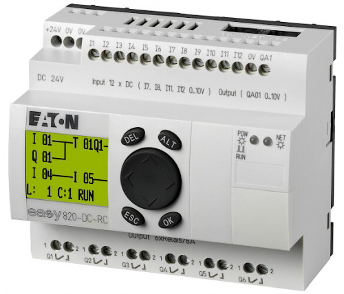
A programmable relay is usually a one-piece design with terminals for connecting power, inputs, outputs, a liquid crystal screen and controls.
At the top of the device are:
At the bottom of the device are:
On the front panel are located:
According to the voltage and type of power, programmable relays are divided into:
The power and type of supply voltage of the programmable relays determine the value of the logical unit on the digital inputs of the device. That is, in order to supply a logical unit to the input of the device, it is necessary to apply a voltage corresponding in its value and type to the supply voltage of the device. Thus, according to the input voltage, there are:
Depending on the type of Easy programmable relay, one or more digital inputs can be used as “fast counters” - for counting pulses with a frequency of up to 3 kHz.
For processing analog signals, such as signals from temperature sensors, wind speed sensors, external potentiometers, Easy programmable relays have two or more analogue 0..10 V (DC) inputs on board.
It should be noted that analog inputs are provided only on devices powered by 12 V (DC), 24 V (AC, DC).
For switching output signals, Easy programmable relays have 4 or more outputs. The device outputs are of two types:
Devices with transistor outputs are mainly used where switching with low currents is necessary, or the task is to transmit the signals of the output functions of the relay to other parts of the automation system.
Direct connection of lighting sources, low-power motors and other consumers with an active load not exceeding 8 A is possible for devices with relay outputs.
Easy800 Series programmable relays have an analog output (0..10 V) on board.
The built-in screen is designed to display textual (in devices of the Easy500, 700, 800 series) and graphic (in devices of the MFD-Titan series) information.
Ethernet - the ability to connect through an expansion module that implements the functions of an OPC server. For the entire line of devices.
Profibus, CANopen, DeviceNet, As-i - the ability to connect via expansion modules. For devices of the Easy700, Easy800 series.
Easy-net - the ability to connect programmable relays to the network. For Easy800 devices, MFD-Titan.

Expansion modules are available for Easy700, Easy800 series devices to increase the number of device inputs and outputs. Expansion modules can be butt-mounted, via an adapter, or installed remotely (up to 100 m). Remote installation is convenient if, for example, you implement a two-room control system.
Only one expansion module can be connected to one programmable Easy relay.
The programmable relays of the Easy800 series have an Easy-net interface on board, which allows you to combine up to 8 devices into a single network, and an expansion module can be connected to each device. Thus, it is possible to organize a system with the number of inputs / outputs up to 328.

Easy programmable relays are available in the Easy500, Easy700, Easy800 and MFD-Titan series devices.
The initial series of programmable relays designed to solve simple automation tasks, such as: controlling the lighting of a small room, heating systems, presence monitoring, starting engine control, compressor or pump control.

Key Features of Easy500 Series Relays
Devices that combine all the advantages of Easy500-series devices, with the ability to connect additional expansion units: analog and digital inputs / outputs, communication modules, etc.
This series of programmable Easy relays is optimal for solving quite complex automation tasks, with the ability to control a large number of signals (lines). Also, the devices are ideal for use in projects involving the further expansion of the capabilities of the control system with minimal cost.
Key Features of Easy700 Series Programmable Relays
The most advanced and most functional series of Easy devices, allowing you to implement a flexible solution to almost any task of home and industrial automation. The Easy800 Series can be expanded with additional functional and communications expansion modules.
Along with the standard functions presented in easy500 / 700, such as multi-function relays, pulse relays, counters, analog comparators, timers, real-time clocks and non-volatile memory, easy800 additionally contains PID controllers, arithmetic units, value scaling units and many other functions . Also, the ability to network up to 8 devices makes easy800 the most powerful programmable relay on the electrical market.
When solving complex tasks, Easy800 programmable relays can be combined into one common network of EasyNet devices.
Key Features of Easy800 Series Programmable Relays:
And so, we examined almost the entire line of devices, we know their main characteristics. It remains to choose the necessary programmable relay to solve our problem.
Since our task is quite trivial, not requiring additional communication and other device capabilities, we will use a simple algorithm to select the suitable Easy programmable relay.
Using the catalog of programmable relays, we select the type of device that is most suitable for our purposes: EASY719-AC-RC10 .
The selected relay has on board:
To develop automation systems based on Easy programmable relays, the device manufacturer offers an easy-to-use and easy-to-use Easy-Soft development environment .
The software makes it easy to "draw" your relay-contactor circuit using a convenient graphical development environment.
If necessary, it is possible to choose one of several types of display of relay-contactor circuits:
Easy-Soft has an emulator that allows you to debug a program without connecting a physical device.
The documentation for the software is available in several languages, including Russian.
You can download the demo version of Easy-Soft here .
The process of writing a program for the Easy programmable relay is reduced to “drawing” the relay-contactor connection diagram in accordance with the obtained logical functions and determining the necessary parameters, such as time constants, timer values, etc.
Launch Easy-Soft and create a new project.
Select the desired device type from the list on the left and drag it into the project window. At the same time, the device version selection menu appears. From the drop-down list, select the version 10-xxxxxxxxx - this corresponds to devices with Cyrillic support.
Next, go to the editing section of the wiring diagram by selecting the appropriate item in the menu at the bottom left.
Set up a convenient option for displaying the connection diagram using the appropriate menu. For me, the first display option is more convenient, so it makes it possible to view the program in the familiar form - from top to bottom. For electrical engineers, perhaps the second option will be more convenient, since it is as close as possible to standard relay-contactor circuits.

Let us pass from the logical functions of the lighting control system synthesized by us in the “theory” section to the relay-contactor circuit. To do this, it is enough to represent all the input and intermediate variables in the form of relay contacts, and the output functions in the form of relay coils.
Since one line of the program can contain only 3 contacts and one coil, if necessary, intermediate variables should be introduced to break up long logical functions. Intermediate variables are called markers in the ideology of relay-contactor circuits.
To determine the end and the beginning of the working day, it is convenient to use the weekly timer (H), which has flexible settings for the days of the week. Also, the use of a weekly timer allows you to use only one variable to determine the boundaries of the working day.
To "draw" the relay-contactor circuit, simply drag the necessary elements from the menu on the left to the workspace of the project. The connection of elements is carried out using the pencil tool.
After adding elements to the diagram, it is necessary to determine their available parameters. Let's see how to do this with the example of a weekly timer.

The weekly timer is designed to initiate any action during the week, depending on the set time limits. The timer has 4 independent channels A, B, C, D. Each of the channels can be configured for certain time intervals. For example, in our case, the configuration of the weekly timer ensures its operation from Monday to Sunday, from 18-45 to 8-45.
You will be right if you notice that our example uses an office space, whose working days are usually Monday through Friday.
The final relay-contactor circuit of our example
After building the relay-contactor circuit, it is convenient to use the program debugging mode. To do this, just go to the Simulation menu .
To simulate, all input and output signals of the device are available, as well as all variables of the programmable relay.
For convenience, debugging - there is the ability to configure the type of input signals. For example, imitating the position of the blinds, it is convenient to configure the corresponding input signal as a self-locking button. That will allow once clicking on it, fix its position.
When using debug mode, the current time of the simulated device is the system time of your computer.
If there is a real physical device, after debugging the operation of the relay-contactor circuit, it is necessary to flash it into a programmable relay. To do this, use the Communication menu item . I think there is no need to comment on individual menu items, as they are intuitive.
When realizing real tasks, the next step would be to physically connect the programmable relay to the executive bodies and mechanisms, in our case, connect to the office network.
It is fair to say that, as with any development from scratch, it is advisable to debug systems built on programmable relays in the form of a prototype assembly. This is quite simple, taking into account the features of the device and the convenience of connecting control and executive bodies.
When designing real control systems, one should be guided by the general rules for connecting programmable relays. You can find detailed information about connections in the documentation for devices (at the end of the article).
The main requirement when connecting the load (incandescent lamps, motors, etc.) is not to exceed the permissible currents on the group of contacts of the output device:
In case of exceeding the permissible loads, for example, when controlling an electric heated floor, intermediate contactors should be used . In this case, the load will be limited only by the power of the intermediate contactor.
I hope that many who did not know about the described class of devices now have the information and basic knowledge to start implementing their ideas that may have arisen when reading this article.
I would like to believe that my work was not in vain and the information presented is useful to people for the practical implementation of their engineering ideas in industry and at home. With Easy programmable relays, it's really easy and fun!
If the Habrosocommunity finds the information interesting, for the future I plan to prepare a series of articles on the practical application of the described devices in automation and industry. I’ll tell you about some undocumented features of Easy programmable relays, for example, how to make a graphical interface with the ability to monitor all internal variables. Yes, you are absolutely right, on the Easy relay you can build a dispatching system with a graphical interface.
[1] Wikipedia is an algebra of logic.
[2] Wikipedia - Carnot maps - methods for minimizing Boolean functions.
[3] Wikipedia is a relay.
[4] Documentation for programmable relays series Easy500, Easy700.
[5] Documentation for Easy800 Series programmable relays.
[6] Easy Relay Training Center - many examples of the use of Easy programmable relays (in Russian).
[7] Software for Easy relays (including in Russian).
[8] Site of the manufacturer.
[9] Easy programmable relay catalog .
[10]Easy is easy . Tutorial. O.A. Andryushchenko, V.A. Vodichev.
Some links to the documentation are given not from the manufacturer’s website, but from the website of my company, since after the merger of Eaton and Moeller corporations, internal resources are being re-designed, and links to documentation may not be available.
UPD 1. Added literature [10] - a textbook for university students. Examples, laboratory work.
UPD 2. Yes, these devices can be programmed directly from the built-in keyboard. Large programs, of course, are not very convenient to type, but for online editing of circuits, this possibility can be used.
UPD 3. Habrozer ShadowHackersuggests that it is more correct to use the terms “normally open contact” and “normally closed contact” in terms of electrical engineering / electronics. In the article I will leave the initial terminology due to the fact that the terms “normally closed contact” and “normally open contact” are used in the Russian-language documentation and catalogs for the device.
On Habré a lot of words have already been said about various automation devices, ranging from simple Arduino to industrial multiprocessor systems. I want to paint another white spot on the habro-automation card with an article on intermediate devices - programmable relays , using the example of Easy microprocessor devices manufactured by Eaton (Moeller) Corporation.
Quite a lot of time has passed since my first acquaintance with this type of device, but still, these “electronic kids” remain indispensable assistants for the implementation of a wide range of engineering and domestic tasks.
A programmable (intelligent) relay is a type of programmable logic controller (PLC).
Programmable relays have found the main application as means of automation of local circuits, individual units of machines and mechanisms, for domestic use.
On the basis of smart relays, various automatic control systems are intuitively and clearly built, for example, control systems for pumping equipment, drilling machines, automatic reserve input systems (ATS). The compact size and ease of programming make it possible to develop elements of the “smart home” system based on programmable relays.
The standard means of describing and constructing programs for these devices are the languages of relay logic ( LD ) or function blocks ( FBD), designed specifically for engineers engaged in the automation of industry and production.
The simplicity of the programming language, the ease of transition from obsolete automation systems based on relay-contactor circuits to microprocessor devices, allowed programmable relays to take a reliable position in the market of automation devices.
Theory
Relay as the main programming operator
Based on the name of the described class of devices, the main element to be operated will be a relay.
Relay - an electromechanical device designed to switch electrical circuits for a given change in electrical or non-electrical input values. A classic relay has a control coil x , and a group of contacts that implement the output function y = f (x) .
When a control voltage is applied to the input of the coil, the contacts change their initial state to inverse.
A contact group can contain two main types of contacts: normally open contacts and normally closed contacts .
Normally open contact - a contact that is in the open state in the absence of voltage on the control coil.
Normally closed contact - a contact that is in a closed state in the absence of voltage on the control coil.
Thus, two main types of functions implemented using relays can be written:
y (x) = x - for normally open contacts;
y (x) = x̅ - for normally closed contacts.
The remaining types of functions implemented using relays are based on giving the contact group additional properties. The functions and types of relay contacts are shown in the figure below.
1 - relay coil (control circuit), 2 - normally open contact, 3 - normally closed contact, 4 - normally open contact with the moderator upon operation, 5 - normally open contact with the moderator upon return, 6 - normally open pulse contact, 7 - normally open contact without self-resetting, 8 - normally closed contact without self-resetting, 9 - normally closed contact with moderator when triggered, 10 - normally closed contact with moderator when returning.
Elements of the theory of discrete automated devices
A discrete automated device is understood to mean a control device that processes a priori and current information into control information, and the carriers of all these components of information are signals that are discrete in level and in time. This means that the signal state of each input (output) of the automated device is characterized by two levels: the minimum, conditionally designated “0”, and the maximum, designated “1”.
Drawing up a control block diagram for the given conditions of its operation is called synthesis . Determining the working conditions of a circuit or its individual elements by the existing structure is called an analysis of control circuits.
Circuits on relay and contactless elements can be composed in two ways.
The first method is experimental, widely used in the practice of logical design of relay-contactor circuits. Based on the given operating conditions of the individual parts of the working machine, a circuit diagram of the automation system is made up. Contactless analogs of relay-contact circuits, in which the specified operating conditions of the circuit are expressed in the form of functions of the algebra of logic, are composed similarly . At the same time, it is advisable to minimize any contact or contactless circuit constructed in such an experimental way. Minimization of circuits is based on the laws of algebra of logic.
Second wayThe construction (synthesis) of circuits is based on a more complete use of the theory of algebra of logic and the principles of formalizing the real working conditions of the automation circuit. In this case, they proceed from the given operating conditions, compiling the corresponding state tables (function maps), where combinations of arguments and values of functions (output signals) are noted in the form of logical “1” and “0”. The main task of the synthesis is to determine this form of expression of the desired logical function, which can be implemented using the minimum number of possibly simplest elements. The synthesis of relay control circuits is reduced to the preparation of a structural formula (analytical expression) that describes the logical functions that must be performed by this device. Then, the resulting algebraic formula is analyzed and a graphic outline of the circuit is made.
The analysis of the full course of the theory of logic and synthesis of circuits is beyond the scope of this article; all those interested in this topic can familiarize themselves with the subject in detail using references to the literature (at the end of the article).
Let's look at the process of creating a control circuit using a simple example from life.
Synthesis of a relay-contactor control circuit using an example
Formulation of the problem
It is necessary to develop a lighting control system for the office space in accordance with the following conditions:
Given an
office space with one main lighting group (fluorescent lamps) and one group of emergency and background lighting.
Electric blinds.
Necessary
- At the end of the working day (18:15), ensure that the main lighting group is turned off and that the emergency lighting is turned on. If the blinds remain closed - ensure their opening.
- Before the beginning of the working day (8:45), turn off the emergency lighting.
- In case of insufficient natural lighting, ensure that the main lighting is switched on by a signal from the dimming sensor, provided that the blinds are open.
- Ensure the inclusion of background lighting with closed blinds. If the main light has been turned on, turn it off.
- When turning on the background lighting, automatically lower the blinds.
Additional terms
- The light sensor has a binary output that can be adjusted to a specific light threshold. In low light - the contact closes.
- The blind drive system has contacts informing of the limit positions.
Decision
Let us first of all determine the correspondence of the input and output signals of the designed system to variables. We agree to denote all input signals by the variables I with resp. index, and all output signals - variables Q with resp. index.
Input variables :
I1 - light sensor signal.
I2 - signal of the upper position of the blinds.
I3 - signal for the lower position of the blinds.
I4 - background light enable signal.
Output variables :
Q1 - turn on / off the main lighting group.
Q2 - turn on / off the emergency lighting.
Q3 - turn on / off the background lighting.
Q4 - raising the blinds.
Q5 - lowering the blinds.
Time variables :
T1 - reaching the end time of the working day.
T2 - reaching the start time of the working day.
Next, we divide our problem into conditional parts and compose logical functions for each of the parts.
- The end of the working day
- Turn off the main light: Q1 = not (T1)
- Turn on the standby light: Q2 = T1
- Open the blinds, if closed: Q4 = not (I2) ⋅T1
- The begining of the work day
- Turn off the standby light: Q2 = not (T2)
- Light level control
- Turning on the main light according to the light sensor, checking whether the blinds are open: Q1 = I1⋅ I2⋅not (T1) ⋅T2
- We control the background lighting
- Turning on the background lighting when the blinds are closed: Q3 = I3
- Turn off the main light when the blinds are closed Q1 = not (I3)
- Management of blinds depending on the included background lighting
- When background lighting is on, lower the blinds, if not at the end of the working day: Q5 = I4⋅not (I3) ⋅not (T1) ⋅T2
So, we got logical functions that describe the behavior of the elements of our system depending on the conditions and disturbing influences. Next, it is necessary to make the transition to a relay-contactor circuit, i.e., describe the operation of our system on real physical devices.
The transition from the functions of the algebra of logic to the relay-contactor circuit is very simple. To do this, it is enough to represent all the input and intermediate variables in the form of relay contacts, and the output functions in the form of relay coils.
A separate word needs to be said about time-dependent variables. In our example, these are variables describing the time interval of the working day, T1 and T2. There are special types of relays — time relays and timers — to represent time-dependent variables .
Iron
To go to the practical part of our task, we need to figure out which hardware is more profitable and convenient to carry out the solution. Manufacturers represent a fairly wide range of programmable relays for optimal cost and functionality solutions for certain types of engineering problems. Let's try to understand this variety.
A programmable relay is usually a one-piece design with terminals for connecting power, inputs, outputs, a liquid crystal screen and controls.
At the top of the device are:
- power connection terminals;
- digital input terminals of the device;
- analog input terminals (0..10 V).
At the bottom of the device are:
- terminals of relay (or transistor) outputs of the device.
On the front panel are located:
- LCD screen - for displaying information messages, editing a program, changing parameters;
- keyboard - to navigate the device menu;
- connector for connecting the programming cable.
Device power
According to the voltage and type of power, programmable relays are divided into:
- devices powered by 12, 24 V (DC);
- devices powered by 24, 110-220 V (AC).
Digital inputs
The power and type of supply voltage of the programmable relays determine the value of the logical unit on the digital inputs of the device. That is, in order to supply a logical unit to the input of the device, it is necessary to apply a voltage corresponding in its value and type to the supply voltage of the device. Thus, according to the input voltage, there are:
- devices with inputs 12, 24 V (DC);
- devices with 24, 110-220 V (AC) inputs.
Depending on the type of Easy programmable relay, one or more digital inputs can be used as “fast counters” - for counting pulses with a frequency of up to 3 kHz.
Analog inputs
For processing analog signals, such as signals from temperature sensors, wind speed sensors, external potentiometers, Easy programmable relays have two or more analogue 0..10 V (DC) inputs on board.
It should be noted that analog inputs are provided only on devices powered by 12 V (DC), 24 V (AC, DC).
Relay and transistor outputs
For switching output signals, Easy programmable relays have 4 or more outputs. The device outputs are of two types:
- transistor outputs, providing the ability to switch small loads up to 0.5 A;
- relay outputs for switching loads up to 8 A (AC1).
Devices with transistor outputs are mainly used where switching with low currents is necessary, or the task is to transmit the signals of the output functions of the relay to other parts of the automation system.
Direct connection of lighting sources, low-power motors and other consumers with an active load not exceeding 8 A is possible for devices with relay outputs.
Analog outputs
Easy800 Series programmable relays have an analog output (0..10 V) on board.
Screen
The built-in screen is designed to display textual (in devices of the Easy500, 700, 800 series) and graphic (in devices of the MFD-Titan series) information.
Communications and system scalability
Ethernet - the ability to connect through an expansion module that implements the functions of an OPC server. For the entire line of devices.
Profibus, CANopen, DeviceNet, As-i - the ability to connect via expansion modules. For devices of the Easy700, Easy800 series.
Easy-net - the ability to connect programmable relays to the network. For Easy800 devices, MFD-Titan.
Expansion modules are available for Easy700, Easy800 series devices to increase the number of device inputs and outputs. Expansion modules can be butt-mounted, via an adapter, or installed remotely (up to 100 m). Remote installation is convenient if, for example, you implement a two-room control system.
Only one expansion module can be connected to one programmable Easy relay.
The programmable relays of the Easy800 series have an Easy-net interface on board, which allows you to combine up to 8 devices into a single network, and an expansion module can be connected to each device. Thus, it is possible to organize a system with the number of inputs / outputs up to 328.
Easy programmable relay line
Easy programmable relays are available in the Easy500, Easy700, Easy800 and MFD-Titan series devices.
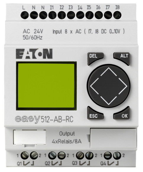
Easy500 Series Programmable Relays
The initial series of programmable relays designed to solve simple automation tasks, such as: controlling the lighting of a small room, heating systems, presence monitoring, starting engine control, compressor or pump control.
Key Features of Easy500 Series Relays
- Supply voltage and voltage of digital inputs: 24 V and 100 - 240 V AC, 12 V and 24 V DC.
- 8 digital inputs.
- 2 analog inputs: 0 - 10 V (0 - 1023 bit), in versions with power supply 12 V, 24 V DC and 24 V AC.
- 4 relay outputs: 8 A, or 4 transistor outputs: 24 V DC / 0.5 A.
- 128 "lines of the program" with 3 contacts and the 1st coil.
- Easy500 series relays do not have the option of connecting expansion modules.
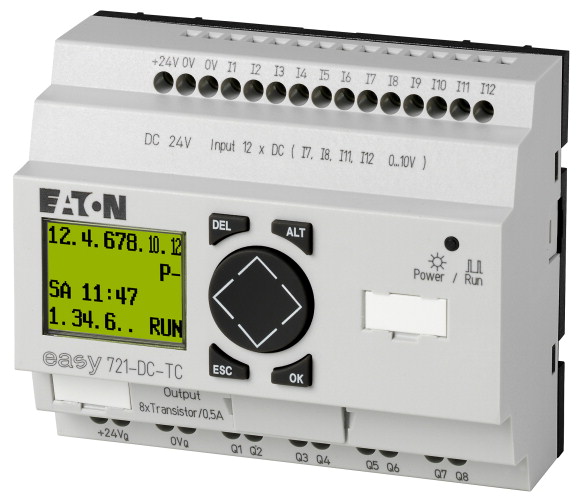
Easy700 Series Programmable Relays
Devices that combine all the advantages of Easy500-series devices, with the ability to connect additional expansion units: analog and digital inputs / outputs, communication modules, etc.
This series of programmable Easy relays is optimal for solving quite complex automation tasks, with the ability to control a large number of signals (lines). Also, the devices are ideal for use in projects involving the further expansion of the capabilities of the control system with minimal cost.
Key Features of Easy700 Series Programmable Relays
- Supply voltage and voltage of digital inputs: 24 V and 100 - 240 V AC, 12 V and 24 V DC.
- 12 digital inputs.
- 4 analog inputs: 0 - 10 V (0 - 1023 bit), in versions with power supply 12 V, 24 V DC and 24 V AC.
- 6 релейных выхода: 8 A, или 8 транзисторных выходов: 24 В DC/0.5 A.
- 128 «строк программы» с 3-мя контактами и 1-й катушкой.
- Возможность подключения блоков расширения.
Программируемые реле серии Easy800
The most advanced and most functional series of Easy devices, allowing you to implement a flexible solution to almost any task of home and industrial automation. The Easy800 Series can be expanded with additional functional and communications expansion modules.
Along with the standard functions presented in easy500 / 700, such as multi-function relays, pulse relays, counters, analog comparators, timers, real-time clocks and non-volatile memory, easy800 additionally contains PID controllers, arithmetic units, value scaling units and many other functions . Also, the ability to network up to 8 devices makes easy800 the most powerful programmable relay on the electrical market.
When solving complex tasks, Easy800 programmable relays can be combined into one common network of EasyNet devices.
Key Features of Easy800 Series Programmable Relays:
- Supply voltage and voltage of digital inputs: 24 V and 100 - 240 V AC, 12 V and 24 V DC.
- 12 digital inputs.
- 4 analog inputs: 0 - 10 V (0 - 1023 bit), in versions with power supply 12 V, 24 V DC and 24 V AC.
- 6 relay outputs: 8 A, or 8 transistor outputs: 24 V DC / 0.5 A.
- 256 "lines of the program" with 4 contacts and the 1st coil.
- Integrated EasyNet interface for connecting devices to the network (up to 8 devices).
- Ability to connect expansion units.
Practice
Device selection
And so, we examined almost the entire line of devices, we know their main characteristics. It remains to choose the necessary programmable relay to solve our problem.
Since our task is quite trivial, not requiring additional communication and other device capabilities, we will use a simple algorithm to select the suitable Easy programmable relay.
- Determine the number of digital inputs . We have 4 input variables I1..I4, so there are enough 4 inputs in the device.
- Определим напряжение питания и тип цифровых входов. Так как мы планируем применять программируемое реле для бытовых нужд, с питанием внутридомовой сети 220 В, 50 Гц, то наиболее подходящее устройство будет с аналогичными требованиями к питанию и значениям напряжения цифровых входов – 220 В, 50 Гц.
- Определим типы и количество выходных контактов. Для управления 5-ю выходными переменными нам необходимо выбрать устройство с соответствующим количеством выходов. Так выходы программируемого реле должны обеспечивать коммутацию внутриофисных источников света и других силовых устройств, то нам необходимо наличие релейных выходов.
Using the catalog of programmable relays, we select the type of device that is most suitable for our purposes: EASY719-AC-RC10 .
The selected relay has on board:
- 12 digital inputs (220 V, 50 Hz);
- 6 relay outputs (load switching up to 8 A);
- real time clock;
- device power - 110-220 V, 50 Hz.
Development environment
To develop automation systems based on Easy programmable relays, the device manufacturer offers an easy-to-use and easy-to-use Easy-Soft development environment .
The software makes it easy to "draw" your relay-contactor circuit using a convenient graphical development environment.
If necessary, it is possible to choose one of several types of display of relay-contactor circuits:
- contacts and coils are displayed in accordance with IEC standards;
- contacts and coils are displayed in accordance with GOST standards;
- pins and coils are displayed according to ANSI standard.
Easy-Soft has an emulator that allows you to debug a program without connecting a physical device.
The documentation for the software is available in several languages, including Russian.
You can download the demo version of Easy-Soft here .
Programming
The process of writing a program for the Easy programmable relay is reduced to “drawing” the relay-contactor connection diagram in accordance with the obtained logical functions and determining the necessary parameters, such as time constants, timer values, etc.
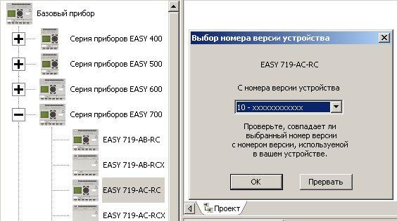
Launch Easy-Soft and create a new project.
Select the desired device type from the list on the left and drag it into the project window. At the same time, the device version selection menu appears. From the drop-down list, select the version 10-xxxxxxxxx - this corresponds to devices with Cyrillic support.
Next, go to the editing section of the wiring diagram by selecting the appropriate item in the menu at the bottom left.
Set up a convenient option for displaying the connection diagram using the appropriate menu. For me, the first display option is more convenient, so it makes it possible to view the program in the familiar form - from top to bottom. For electrical engineers, perhaps the second option will be more convenient, since it is as close as possible to standard relay-contactor circuits.
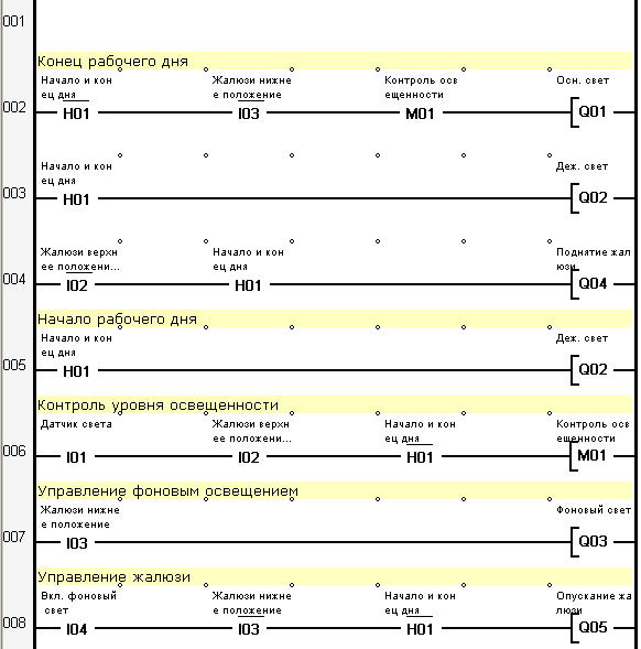
Let us pass from the logical functions of the lighting control system synthesized by us in the “theory” section to the relay-contactor circuit. To do this, it is enough to represent all the input and intermediate variables in the form of relay contacts, and the output functions in the form of relay coils.
Since one line of the program can contain only 3 contacts and one coil, if necessary, intermediate variables should be introduced to break up long logical functions. Intermediate variables are called markers in the ideology of relay-contactor circuits.
To determine the end and the beginning of the working day, it is convenient to use the weekly timer (H), which has flexible settings for the days of the week. Also, the use of a weekly timer allows you to use only one variable to determine the boundaries of the working day.
To "draw" the relay-contactor circuit, simply drag the necessary elements from the menu on the left to the workspace of the project. The connection of elements is carried out using the pencil tool.
After adding elements to the diagram, it is necessary to determine their available parameters. Let's see how to do this with the example of a weekly timer.
The weekly timer is designed to initiate any action during the week, depending on the set time limits. The timer has 4 independent channels A, B, C, D. Each of the channels can be configured for certain time intervals. For example, in our case, the configuration of the weekly timer ensures its operation from Monday to Sunday, from 18-45 to 8-45.
You will be right if you notice that our example uses an office space, whose working days are usually Monday through Friday.
The final relay-contactor circuit of our example
Debugging
After building the relay-contactor circuit, it is convenient to use the program debugging mode. To do this, just go to the Simulation menu .
To simulate, all input and output signals of the device are available, as well as all variables of the programmable relay.
For convenience, debugging - there is the ability to configure the type of input signals. For example, imitating the position of the blinds, it is convenient to configure the corresponding input signal as a self-locking button. That will allow once clicking on it, fix its position.
When using debug mode, the current time of the simulated device is the system time of your computer.
Firmware
If there is a real physical device, after debugging the operation of the relay-contactor circuit, it is necessary to flash it into a programmable relay. To do this, use the Communication menu item . I think there is no need to comment on individual menu items, as they are intuitive.
Connection and assembly of the control system
When realizing real tasks, the next step would be to physically connect the programmable relay to the executive bodies and mechanisms, in our case, connect to the office network.
It is fair to say that, as with any development from scratch, it is advisable to debug systems built on programmable relays in the form of a prototype assembly. This is quite simple, taking into account the features of the device and the convenience of connecting control and executive bodies.
When designing real control systems, one should be guided by the general rules for connecting programmable relays. You can find detailed information about connections in the documentation for devices (at the end of the article).
The main requirement when connecting the load (incandescent lamps, motors, etc.) is not to exceed the permissible currents on the group of contacts of the output device:
- 8 A active load (AC1) for devices with relay outputs;
- 0.5 A - for devices with transistor outputs.
In case of exceeding the permissible loads, for example, when controlling an electric heated floor, intermediate contactors should be used . In this case, the load will be limited only by the power of the intermediate contactor.
Conclusion
I hope that many who did not know about the described class of devices now have the information and basic knowledge to start implementing their ideas that may have arisen when reading this article.
I would like to believe that my work was not in vain and the information presented is useful to people for the practical implementation of their engineering ideas in industry and at home. With Easy programmable relays, it's really easy and fun!
If the Habrosocommunity finds the information interesting, for the future I plan to prepare a series of articles on the practical application of the described devices in automation and industry. I’ll tell you about some undocumented features of Easy programmable relays, for example, how to make a graphical interface with the ability to monitor all internal variables. Yes, you are absolutely right, on the Easy relay you can build a dispatching system with a graphical interface.
Helpful information
[1] Wikipedia is an algebra of logic.
[2] Wikipedia - Carnot maps - methods for minimizing Boolean functions.
[3] Wikipedia is a relay.
[4] Documentation for programmable relays series Easy500, Easy700.
[5] Documentation for Easy800 Series programmable relays.
[6] Easy Relay Training Center - many examples of the use of Easy programmable relays (in Russian).
[7] Software for Easy relays (including in Russian).
[8] Site of the manufacturer.
[9] Easy programmable relay catalog .
[10]Easy is easy . Tutorial. O.A. Andryushchenko, V.A. Vodichev.
Some links to the documentation are given not from the manufacturer’s website, but from the website of my company, since after the merger of Eaton and Moeller corporations, internal resources are being re-designed, and links to documentation may not be available.
UPD 1. Added literature [10] - a textbook for university students. Examples, laboratory work.
UPD 2. Yes, these devices can be programmed directly from the built-in keyboard. Large programs, of course, are not very convenient to type, but for online editing of circuits, this possibility can be used.
UPD 3. Habrozer ShadowHackersuggests that it is more correct to use the terms “normally open contact” and “normally closed contact” in terms of electrical engineering / electronics. In the article I will leave the initial terminology due to the fact that the terms “normally closed contact” and “normally open contact” are used in the Russian-language documentation and catalogs for the device.