We are building a caterpillar Bluetooth robot with a camera. Part 3
In the previous series:
Part 1
Part 2
Well, has everyone already ordered spare parts and assembled robots? It's time for the robot to revive.
Today we will analyze the software.
The option that I offer is as simple as possible . Do not expect unique abilities from him. His task is justto go to work. Fault tolerance, smooth control and additional functions - this is the scope for creativity, which I leave to everyone, so as not to deprive this pleasure. The code is very simple and therefore far from optimal and not secure and generally not beautiful. If there are suggestions for improving it - offer your own options, directly pieces of code explaining why and why it would be better.
Unconstructive criticism of what has been done poorly is not particularly needed :) I already know about the shortcomings. But if something is not clear, ask, I will explain.
So let's go!
Let's divide the task into simple steps: On-
board controller
PC / Laptop
Since we use a ready-made MotorShield and not a bare H-bridge or L293D / L298N, there is nothing particularly complicated to invent. We vspolzuemsya library AFMotor . If you have a Motorshield V3 and you need an SPI bus, take the modified version .
I usually write comments in English, as it’s simpler and shorter.
Declare variables for controlling motors. the right motor is connected to the 4th port, and the left motor to the 3rd port.
depending on the given direction and speed, we command the motors to rotate (for the left motor):
For the right engine the same:
lDirection (or rDirection) takes the following values:
0 - stop the motor
1 - forward rotation
2 - reverse rotation.
To control the servos, we declare two objects panServo (responsible for the rotation of the camera) and tiltServo (responsible for the tilt). Since the servo is mechanical and does not rotate instantly, we introduce a variable for the delay required by the drive to work out the rotation command (15 ms is enough)
previousMillis and currentMillis are used to avoid waiting stupidly in the control loop when the servo runs. We check - if 15 ms has not passed since the last command, then it is useless to command the servo - it is still busy.
Piece responsible for the rotation of the camera:
The bluetooth module from the point of view of the Arduino is simply a serial (UART) port.
Therefore, we will interrogate in a cycle to check whether something has come from the computer. If something is found in the buffer, then we are looking for the beginning of the packet in the stream - the $ FF byte (the extreme positions of the servos and the motor speed values of 255 are practically useless - the servants abut earlier, and the speed of 250-255 does not differ, so this value will occur extremely rarely and this will allow us to catch the beginning of the package, we can increase reliability by complicating the algorithm, but this is quite enough for us).
Having found the header, we accept a byte in which the direction of the engines is encoded in 2 bits per engine. Then we read the speed of the engines - 1 byte per engine (lSpeed, rSpeed) and the position of the camera's servo drives (pan, tilt).
Next, we highlight the directions for the right and left engines
and if the direction or speed has changed since the last command received, then set the speed of the engines and rotate the camera.
This is the whole main work cycle:
As you can see, it’s almost nowhere easier :)
You can download the sketch from the project page in Google code.
We taught the chassis to execute commands. Now we need to learn how to send them.
Those who are too lazy to understand programming or reluctant to install Delphi can download the compiled version
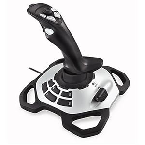
(works with the Logitech Extreme 3D Pro joystick or the Chinese EasyTouch gamepad).

With the rest we go further :)
We will need:
Moving forward and backward does not cause any difficulties - just set the same left and right motor speeds and the same direction.
For turns in motion, we introduce the concept of Steer - the value of deviation from direct movement. The engine speeds are calculated for moving forward and backward as follows:
That is, when moving forward from the speed of the left engine, we subtract the deviation, we add to the speed of the right one. It turns out the effect of braking one of the tracks and the chassis smoothly turns, without stopping completely. When moving backward, the signs simply change.
Well, we check whether the speed has exceeded the maximum permissible values. In particular, this is useful for those who have powered motors with voltage higher than they should - just limit the maximum speed and the motors will be intact.
Examples of control:
go forward - the direction to both motors "1", the same speed
to go back - the direction to both motors "2", the same speed
to turn in moving left / rightset the same direction, different speeds. Turns to a side whose speed is less.
for turning in place - the speed is the same, the direction of the motors is different - it will turn around the center.
stop - direction “0” for both motors
When adding a bluetooth module to a PC, 2 virtual COM ports are formed - one inbound, one outbound.
To connect to the robot, you just need to open the outgoing port. You can specify in the list of ports in bluetooth settings or by brute force method - when connected to the correct one, the program will not swear and the LED on the module stops flashing - the connection is established, we can assume that we are connected directly to the robot.
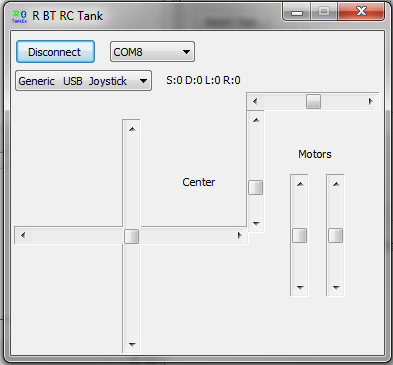
For convenience, I wrote a small class called TRCTank, which implements all actions related to communication with the robot.
Connect and Disconnect essentially just open / close the port and check the current state so as not to try to open the open or close the closed port.
To send a command to the robot, we form a header that the robot will catch (we have a byte with code 255). And then we write down the commands in the order that the robot is waiting for them. It turns out such a structure
In the function of sending a command, the only thing worth mentioning is the packing of directions for both engines in one byte with an offset of 2 bits. The rest is obvious.
Unfortunately, there is not much documentation on working with HID devices that is sensible on the Internet. As a result, I went through a bunch of outdated codes that send to work through the midi port or consider joysticks as a device with 2 axes and 4 buttons. This option did not suit me. There was no information on the TjvJoystick component anywhere, so I stumbled upon it by accident. It's a pity, at this point I already wrote my component :) So if you are not too lazy to figure it out, then you can use the ready-made component from JEDI VCL.
I work with the HID device directly and analyze Report from it by byte. But all the joystick axes are available (EasyTouch has 4 of them) and all buttons (10-12 of my joysticks).
It works like this: using the TjvHIDDeviceController component on the form, we get a list of HID devices in the system and output it to the combo box. We give the selected device to an object of the TRjoystick class by calling SelectJoystickByID (VID, PID: Word); (Selected by VendorID and ProductID - you can see them, for example, in the device manager of the system).
The TRjoystick class performs a checkout, being able to receive reports from the joystick, decrypts the values, sets the properties of buttons and axes, and calls the handler procedure. In our program, the handler looks like this:
First, we give the raw values of the coordinates of the axes to the speed range -256..256 and directions -127..128.
Since, with linear control at low speeds, the motors do not have the strength to move the robot from the place, we introduce small dead zones (empirically) - it will only move from a certain speed value. (ApplyDeadZone (Speed, DeadX); ApplyDeadZone (Steer, DeadY);)
After taking the rudder into account, we check that the speeds have not climbed out of the range and show the speed of the motors on the form with sliders.
Then, depending on the position of the hat, we change the direction of the camera or center it, we also check the limitations (the servos abut mechanically usually before they reach the digital control limits). display the position of the camera on another pair of sliders, display the speed and send a command to the tank.
There are various experiments in the code, pieces responsible for saving the selected port and joystick, saving and loading the control and centering limits of the camera, it is possible to return control not by the joystick, but directly pulling the speed and direction sliders. But this does not concern the main task of management. You can use the code as you like, you can even “arrange BolgenOS” if you want :)
You can download the source code of the R BT RC Tank on the project website in Google code.
I tried to remove the control process from the first person, but shooting the screen with a camera is an ungrateful task, it came out rather mediocre. But the general meaning is clear.
PS right now the chassis is disassembled for rework, so I can’t quickly check any changes in the code on the hardware. But the version available for download is fully functional, as seen in the video.
Part 1
Part 2
Well, has everyone already ordered spare parts and assembled robots? It's time for the robot to revive.
Today we will analyze the software.
The option that I offer is as simple as possible . Do not expect unique abilities from him. His task is just
Unconstructive criticism of what has been done poorly is not particularly needed :) I already know about the shortcomings. But if something is not clear, ask, I will explain.
So let's go!
Let's divide the task into simple steps: On-
board controller
- Controlling caterpillar motors for forward / reverse and cornering
- Camera Servo Control
- Receiving via bluetooth and executing motion commands and controlling camera servos
PC / Laptop
- Calculation of the speed of motors for setting the direction of movement
- Transfer control packets via bluetooth
- Joystick connection for easy control
Controlling caterpillar motors for forward / reverse and cornering
Since we use a ready-made MotorShield and not a bare H-bridge or L293D / L298N, there is nothing particularly complicated to invent. We vspolzuemsya library AFMotor . If you have a Motorshield V3 and you need an SPI bus, take the modified version .
I usually write comments in English, as it’s simpler and shorter.
Declare variables for controlling motors. the right motor is connected to the 4th port, and the left motor to the 3rd port.
AF_DCMotor rMotor(4);  //Right motor
AF_DCMotor lMotor(3);  //Left motor
depending on the given direction and speed, we command the motors to rotate (for the left motor):
      switch (lDirection){
        case 0:
          lMotor.run(RELEASE);
          break;
        case 1:
          lMotor.run(FORWARD);
          lMotor.setSpeed(lSpeed);
          break;
        case 2:
          lMotor.run(BACKWARD);
          lMotor.setSpeed(lSpeed);
          break;
      }
For the right engine the same:
      switch (rDirection){
        case 0:
          rMotor.run(RELEASE);
          break;
        case 1:
          rMotor.run(FORWARD);
          rMotor.setSpeed(rSpeed);
          break;
        case 2:
          rMotor.run(BACKWARD);
          rMotor.setSpeed(rSpeed);
          break;
      }
lDirection (or rDirection) takes the following values:
0 - stop the motor
1 - forward rotation
2 - reverse rotation.
Camera Servo Control
To control the servos, we declare two objects panServo (responsible for the rotation of the camera) and tiltServo (responsible for the tilt). Since the servo is mechanical and does not rotate instantly, we introduce a variable for the delay required by the drive to work out the rotation command (15 ms is enough)
Servo panServo, tiltServo;
long interval = 15;    // interval at which to control servo
long previousMillis = 0;
unsigned long currentMillis;
previousMillis and currentMillis are used to avoid waiting stupidly in the control loop when the servo runs. We check - if 15 ms has not passed since the last command, then it is useless to command the servo - it is still busy.
Piece responsible for the rotation of the camera:
      //Rotate camera
      currentMillis = millis();
      if(currentMillis - previousMillis > interval) {
        previousMillis = currentMillis;
        if (lastPan!=pan) panServo.write(pan);	     // tell pan servo to go to position
        if (lastTilt!=tilt) tiltServo.write(tilt);   // tell tilt servo to go to position
        lastPan=pan;
        lastTilt=tilt;
      }
Receiving via bluetooth and executing motion commands and controlling camera servos
The bluetooth module from the point of view of the Arduino is simply a serial (UART) port.
Therefore, we will interrogate in a cycle to check whether something has come from the computer. If something is found in the buffer, then we are looking for the beginning of the packet in the stream - the $ FF byte (the extreme positions of the servos and the motor speed values of 255 are practically useless - the servants abut earlier, and the speed of 250-255 does not differ, so this value will occur extremely rarely and this will allow us to catch the beginning of the package, we can increase reliability by complicating the algorithm, but this is quite enough for us).
Having found the header, we accept a byte in which the direction of the engines is encoded in 2 bits per engine. Then we read the speed of the engines - 1 byte per engine (lSpeed, rSpeed) and the position of the camera's servo drives (pan, tilt).
  if (Serial.available()>0) {
    Header=Serial.read();
    //If header found then get and process Cmd
    if (Header==255){
      while(Serial.available()<5){};
      Direction=Serial.read();
      lSpeed=Serial.read();
      rSpeed=Serial.read();
      pan=Serial.read();
      tilt=Serial.read();
Next, we highlight the directions for the right and left engines
      lDirection=Direction & 0x03;
      rDirection=(Direction & 0x0C) >> 2;
and if the direction or speed has changed since the last command received, then set the speed of the engines and rotate the camera.
This is the whole main work cycle:
void loop() {
  if (Serial.available()>0) {
    Header=Serial.read();
    //If header found then get and process Cmd
    if (Header==255){
      while(Serial.available()<5){};
      Direction=Serial.read();
      lSpeed=Serial.read();
      rSpeed=Serial.read();
      pan=Serial.read();
      tilt=Serial.read();
      lDirection=Direction & 0x03;
      rDirection=(Direction & 0x0C) >> 2;
      //Left
     if ((lastlDir!=lDirection) or (lastlSpeed!=lSpeed)){
      switch (lDirection){
        case 0:
          lMotor.run(RELEASE);
          break;
        case 1:
          lMotor.run(FORWARD);
          lMotor.setSpeed(lSpeed);
          break;
        case 2:
          lMotor.run(BACKWARD);
          lMotor.setSpeed(lSpeed);
          break;
      }
      lastlDir=lDirection;
      lastlSpeed=lSpeed;
     }
      //Right
     if ((lastrDir!=rDirection) or (lastrSpeed!=rSpeed)){
      switch (rDirection){
        case 0:
          rMotor.run(RELEASE);
          break;
        case 1:
          rMotor.run(FORWARD);
          rMotor.setSpeed(rSpeed);
          break;
        case 2:
          rMotor.run(BACKWARD);
          rMotor.setSpeed(rSpeed);
          break;
      }
      lastrDir=rDirection;
      lastrSpeed=rSpeed;
     }
      //Rotate camera
      currentMillis = millis();
      if(currentMillis - previousMillis > interval) {
        previousMillis = currentMillis;
        if (lastPan!=pan) panServo.write(pan);			// tell pan servo to go to position
        if (lastTilt!=tilt) tiltServo.write(tilt);		// tell tilt servo to go to position
        lastPan=pan;
        lastTilt=tilt;
      }
    }
  }
}
As you can see, it’s almost nowhere easier :)
You can download the sketch from the project page in Google code.
We taught the chassis to execute commands. Now we need to learn how to send them.
Those who are too lazy to understand programming or reluctant to install Delphi can download the compiled version
(works with the Logitech Extreme 3D Pro joystick or the Chinese EasyTouch gamepad).
With the rest we go further :)
We will need:
- Delphi 2010 (you can also Delphi 7, just a couple of lines need to be corrected in the project file)
- TComPort component from the open ComPort Library (I have 4.11s installed)
- Components TjvHIDDevice, TjvHIDDeviceController from JEDI VCL . I use v3.38, you can download fresher. Put it whole, come in handy
Calculation of the speed of motors for setting the direction of movement
Moving forward and backward does not cause any difficulties - just set the same left and right motor speeds and the same direction.
For turns in motion, we introduce the concept of Steer - the value of deviation from direct movement. The engine speeds are calculated for moving forward and backward as follows:
  if Speed>0 then begin
    //Forward
    //Left/Right turn
    lSpeed:=Speed-Steer;
    rSpeed:=Speed+Steer;
    if lSpeed<0 then lSpeed:=0;
    if rSpeed<0 then rSpeed:=0;
    if lSpeed>MaxSpeed then lSpeed:=MaxSpeed;
    if rSpeed>MaxSpeed then rSpeed:=MaxSpeed;
  end else begin
    //Backward
    //Left/Right turn
    lSpeed:=Speed+Steer;
    rSpeed:=Speed-Steer;
    if lSpeed>0 then  lSpeed:=0;
    if rSpeed>0 then  rSpeed:=0;
    if lSpeed<(-MaxSpeed) then  lSpeed:=-MaxSpeed;
    if rSpeed<(-MaxSpeed) then  rSpeed:=-MaxSpeed;
  end;
That is, when moving forward from the speed of the left engine, we subtract the deviation, we add to the speed of the right one. It turns out the effect of braking one of the tracks and the chassis smoothly turns, without stopping completely. When moving backward, the signs simply change.
Well, we check whether the speed has exceeded the maximum permissible values. In particular, this is useful for those who have powered motors with voltage higher than they should - just limit the maximum speed and the motors will be intact.
Examples of control:
go forward - the direction to both motors "1", the same speed
to go back - the direction to both motors "2", the same speed
to turn in moving left / rightset the same direction, different speeds. Turns to a side whose speed is less.
for turning in place - the speed is the same, the direction of the motors is different - it will turn around the center.
stop - direction “0” for both motors
Transfer control packets via bluetooth
When adding a bluetooth module to a PC, 2 virtual COM ports are formed - one inbound, one outbound.
To connect to the robot, you just need to open the outgoing port. You can specify in the list of ports in bluetooth settings or by brute force method - when connected to the correct one, the program will not swear and the LED on the module stops flashing - the connection is established, we can assume that we are connected directly to the robot.
procedure TfTank.bConnectClick(Sender: TObject);
begin
  if Tank.Connected then begin
    Tank.Disconnect;
    bConnect.Caption:='Connect';
  end else begin
    Tank.Port:=cbPort.Text;
    Tank.Connect;
    bConnect.Caption:='Disconnect';
    MessageBeep(MB_ICONINFORMATION);
  end;
end;
For convenience, I wrote a small class called TRCTank, which implements all actions related to communication with the robot.
  TRCTank=class
  private
    fPort:string;
    ComPort:TComPort;
    Cmd, lastCmd:TControlPacket;
    fConnected:Boolean;
    function isConnected: boolean;
  protected
  public
    constructor Create;
    destructor  Destroy;override;
    procedure   Connect;
    procedure   Disconnect;
    procedure   SendCommand(lDir,left, rDir, right, pan, tilt:Byte);
    property    Port:string read fPort write fPort;
    property    Connected:boolean read isConnected;
  end;
Connect and Disconnect essentially just open / close the port and check the current state so as not to try to open the open or close the closed port.
To send a command to the robot, we form a header that the robot will catch (we have a byte with code 255). And then we write down the commands in the order that the robot is waiting for them. It turns out such a structure
  TControlPacket=record
    Header,
    Direction,
    lSpeed,     //left motor speed
    rSpeed  :Byte;//right motor speed
    pan,
    tilt    :Byte; //Camera pan & tilt
  end;
In the function of sending a command, the only thing worth mentioning is the packing of directions for both engines in one byte with an offset of 2 bits. The rest is obvious.
procedure TRCTank.SendCommand;
begin
  if not fConnected then Exit;
  Cmd.Header:=255;
  Cmd.Direction:=lDir + rDir shl 2;
  Cmd.lSpeed:=left;
  Cmd.rSpeed:=right;
  Cmd.pan:=pan;
  Cmd.tilt:=tilt;
  if (lastCmd.Direction=Cmd.Direction) and
    (lastCmd.lSpeed=Cmd.lSpeed) and
    (lastCmd.rSpeed=Cmd.rSpeed) and
    (lastCmd.pan=Cmd.pan) and
    (lastCmd.tilt=Cmd.tilt) then Exit;
  ComPort.Write(cmd, SizeOf(cmd));
  lastCmd:=Cmd;
end;
Joystick connection for easy control
Unfortunately, there is not much documentation on working with HID devices that is sensible on the Internet. As a result, I went through a bunch of outdated codes that send to work through the midi port or consider joysticks as a device with 2 axes and 4 buttons. This option did not suit me. There was no information on the TjvJoystick component anywhere, so I stumbled upon it by accident. It's a pity, at this point I already wrote my component :) So if you are not too lazy to figure it out, then you can use the ready-made component from JEDI VCL.
I work with the HID device directly and analyze Report from it by byte. But all the joystick axes are available (EasyTouch has 4 of them) and all buttons (10-12 of my joysticks).
It works like this: using the TjvHIDDeviceController component on the form, we get a list of HID devices in the system and output it to the combo box. We give the selected device to an object of the TRjoystick class by calling SelectJoystickByID (VID, PID: Word); (Selected by VendorID and ProductID - you can see them, for example, in the device manager of the system).
The TRjoystick class performs a checkout, being able to receive reports from the joystick, decrypts the values, sets the properties of buttons and axes, and calls the handler procedure. In our program, the handler looks like this:
procedure TfTank.OnJoyData;
var
  Hat:THatPosition;
  CenterCamera:Boolean;
begin
  Hat:=hCenter;
  CenterCamera:=False;
  //Easy touch joystick
  if (joyPID=6) and (joyVID=121) then begin
    scrPitch.Position:=TREasyTouchJoystick(Joy).rZ;
    scrAileron.Position:=TREasyTouchJoystick(Joy).Z;
    scrRudder.Position:=TREasyTouchJoystick(Joy).X;
    scrThrottle.Position:=TREasyTouchJoystick(Joy).Y;
    cbFire.Checked:=TREasyTouchJoystick(Joy).Btn1;
    cbAltFire.Checked:=TREasyTouchJoystick(Joy).Btn10;
    Hat:=TREasyTouchJoystick(Joy).Hat;
    CenterCamera:=TREasyTouchJoystick(Joy).Btn2;
    Speed:=Round(((TREasyTouchJoystick(Joy).rZ)-127)*2);
    Steer:=Round((TREasyTouchJoystick(Joy).Z)-127)*2;
  end;
  //Logitech Extreme 3D Pro
  if (joyPID=49685) and (joyVID=1133) then begin
    scrPitch.Position:=TRLogitechExtreme(Joy).Pitch;
    scrAileron.Position:=TRLogitechExtreme(Joy).Aileron;
    scrRudder.Position:=TRLogitechExtreme(Joy).Rudder;
    scrThrottle.Position:=TRLogitechExtreme(Joy).Throttle;
    cbFire.Checked:=TRLogitechExtreme(Joy).Btn1;
    cbAltFire.Checked:=TRLogitechExtreme(Joy).Btn2;
    Hat:=TRLogitechExtreme(Joy).Hat;
    CenterCamera:=TRLogitechExtreme(Joy).Btn1;
    Speed:=(TRLogitechExtreme(Joy).Pitch div 8)-255;   //4096 to -256..256
    Steer:=(TRLogitechExtreme(Joy).Aileron div 4)-127; //1024 to -127..128
  end;
  ApplyDeadZone(Speed,DeadX);
  ApplyDeadZone(Steer,DeadY);
  if Speed>MaxSpeed then Speed:=MaxSpeed;
  if Speed<-MaxSpeed then Speed:=-MaxSpeed;
  if Speed>0 then begin
    //Forward
    //Left/Right turn
    lSpeed:=Speed-Steer;
    rSpeed:=Speed+Steer;
    if lSpeed<0 then lSpeed:=0;
    if rSpeed<0 then rSpeed:=0;
    if lSpeed>MaxSpeed then lSpeed:=MaxSpeed;
    if rSpeed>MaxSpeed then rSpeed:=MaxSpeed;
  end else begin
    //Backward
    //Left/Right turn
    lSpeed:=Speed+Steer;
    rSpeed:=Speed-Steer;
    if lSpeed>0 then  lSpeed:=0;
    if rSpeed>0 then  rSpeed:=0;
    if lSpeed<(-MaxSpeed) then  lSpeed:=-MaxSpeed;
    if rSpeed<(-MaxSpeed) then  rSpeed:=-MaxSpeed;
  end;
  scrLeft.Position:=-lSpeed;
  scrRight.Position:=-rSpeed;
  if (cbAltFire.Checked) and (bConnect.Caption='Connect') then bConnect.OnClick(Self);
  case Hat of
    hUp: Inc(Tilt);
    hUpRight:begin
        Inc(Tilt);Dec(pan);
      end;
    hRight: Dec(pan);
    hRightDown: begin
        Dec(Pan); Dec(tilt);
      end;
    hDown: Dec(Tilt);
    hLeftDown: begin
        Inc(pan);Dec(tilt);
      end;
    hLeft: Inc(pan);
    hLeftUp: begin
        Inc(pan);Inc(tilt);
      end;
    hCenter: if CenterCamera then begin
       pan:=panCenter;
       tilt:=tiltCenter;
    end;
  end;
  //Limit Pan&Tilt range
  if panmaxPan then pan:=maxPan;
  if tilt>maxTilt then tilt:=maxTilt;
  //Show info
  lJoy.Caption:='S:'+IntToStr(Speed)+' D:'+InttoStr(Steer)+' L:'+InttoStr(lSpeed)+' R:'+InttoStr(rSpeed);
  lhat.Caption:=THatPosString[Integer(Hat)];
  //Show camera position on sliders
  scrPan.Position:=pan;
  scrTilt.Position:=tilt;
  //Send command to tank
  Command2Tank;
end;
First, we give the raw values of the coordinates of the axes to the speed range -256..256 and directions -127..128.
Since, with linear control at low speeds, the motors do not have the strength to move the robot from the place, we introduce small dead zones (empirically) - it will only move from a certain speed value. (ApplyDeadZone (Speed, DeadX); ApplyDeadZone (Steer, DeadY);)
After taking the rudder into account, we check that the speeds have not climbed out of the range and show the speed of the motors on the form with sliders.
Then, depending on the position of the hat, we change the direction of the camera or center it, we also check the limitations (the servos abut mechanically usually before they reach the digital control limits). display the position of the camera on another pair of sliders, display the speed and send a command to the tank.
procedure TfTank.Command2Tank;
begin
  lDir:=0;
  rDir:=0;
  //prepare rDir, lDir data based on tracks speed
  case  lSpeed of
   0:lDir:=0; //stop
   1..255:  lDir:=1; //forward
   -255..-1:lDir:=2; //backward
  end;
  case rSpeed of
   0:rDir:=0; //stop
   1..255:  rDir:=1; //forward
   -255..-1:rDir:=2; //backward
  end;
  Tank.SendCommand(lDir,Abs(lSpeed),rDir,Abs(rSpeed), pan, tilt);
end;
There are various experiments in the code, pieces responsible for saving the selected port and joystick, saving and loading the control and centering limits of the camera, it is possible to return control not by the joystick, but directly pulling the speed and direction sliders. But this does not concern the main task of management. You can use the code as you like, you can even “arrange BolgenOS” if you want :)
You can download the source code of the R BT RC Tank on the project website in Google code.
I tried to remove the control process from the first person, but shooting the screen with a camera is an ungrateful task, it came out rather mediocre. But the general meaning is clear.
PS right now the chassis is disassembled for rework, so I can’t quickly check any changes in the code on the hardware. But the version available for download is fully functional, as seen in the video.