Video player from improvised materials
- From the sandbox
- Tutorial
 This article will tell you how to make a video player from items that can be found in the pantry of any IT specialist. Arduino, Vogue magazine, and the display from Nokia 3310 can be left alone - we do not need them. The presence of a soldering iron is welcome, but you can do without it.
 Judging by the speed of technological development, in about ten years a generation will appear that has never seen a cathode ray tube. Meanwhile, the history of video displays began with completely different devices ...
History
In 1884, a few years before the invention of radio, German student Paul Nipkow (Paul Nipkow) patented the world's first television system. It wasn’t important with electronics at that time, so the electromechanical approach was used to construct the image: the brightness of the pixel was set by an electric lamp, and its position was set mechanically using a rotating disk. Holes arranged in a spiral were arranged in the disk; thus, when the disk rotates, holes flying one at a time “scanned” a fixed field of view. And although the inventor himself never created such a system, up to the 1930s, Nipkov’s disk was popular with other television developers.
 On the transmitting side, behind the disk, there was a photocell evaluating the brightness of each image point. The ferroelectric photodetectors of that time had low sensitivity, so the studio had to be flooded with bright light, and the faces of the announcers were made up with purple paint in order to improve image quality. In another embodiment, the sources and detectors of light were interchanged: a bright arc lamp was placed behind the disk, and a luminous dot was darkened by a studio; reflected light was captured by a set of photocells.
 Viewers, in turn, looked through the Nipkov disk at a neon lamp, the brightness of which was determined by the photocell readings transmitted from the studio. The picture was the size of a postage stamp, so a magnifying lens was placed in front of the disc. It is interesting that the image data fit into the sound spectrum, and was received by the most ordinary radio receiver. In fact, the TV was a simple set-top box, which could collect a ham radio. The main problem was to get neonka - everything else, from marking the disk to winding the electric motor, was done by hand. (In especially advanced cases, instead of the electric motor, a handle was placed, which the viewer had to rotate at a speed of strictly 50 rpm.)
Of course, over the past eighty years, technology has stepped forward, and no one is surprised by devices like the “3D HD display with an active matrix on organic LEDs” (in the 1930s, by the way, an ordinary person would understand only the word “organic”). On the other hand, this means that a modern engineer in a heap of old rubbish can find even a bright “neon” (LED), at least a precision stepper motor (in an old CD-ROM), not to mention lightweight and well-balanced compact disks ...
Mechanical TV Assembly
Although our device will work on recorded signals, and it is more appropriate to call it a video player, it can nevertheless be used to show NBTV television broadcasts broadcast by some amateur radio enthusiasts .
We will need four components:
- Nipkova Disk
- Motor for disc rotation
- Adjustable light source
- Video source
Nipkova Disk
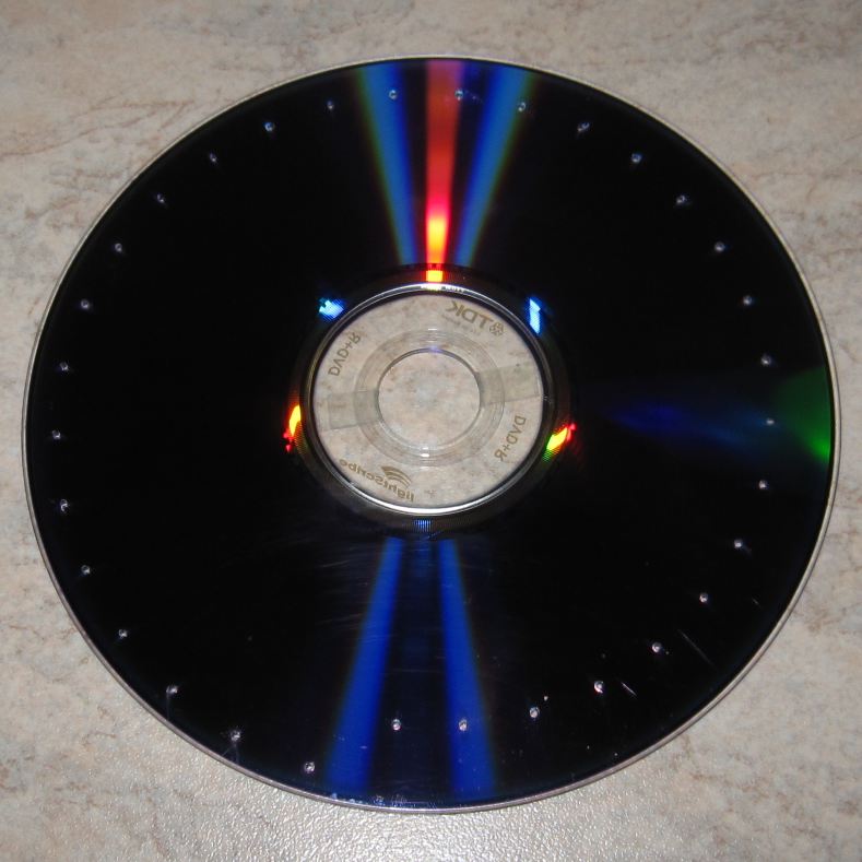
In the thirties, disks were made from cardboard, thin aluminum, or even from a paper ring on a wire frame. We will take advantage of the delights of progress and take an unnecessary CD, the benefit of their bulk. If you have a choice, it is better to take a disc with a dark surface - this will improve the contrast of the image.
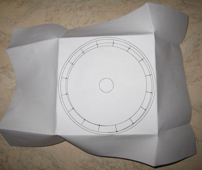 In the last century, marking holes required great accuracy, the ability to handle a protractor, and a special compass to draw a spiral. We will mark the disk virtually in a graphical editor (for example, Inkscape ) and print the finished drawingon the printer. Then we bend the paper along the edges of the printed circle (see photo), and wrap the disk in the resulting paper envelope. The printed image should remain outside, it will serve as a guideline for drilling. Happy owners of drives that support LightScribe / LabelFlash technology can print a mask with holes right on the surface of the disc.
Finally, we take a microdrill with a drill 0.6–0.8 mm and drill a disk according to the marking. No microdrills? No problem! The fact is that on CDs (but not DVDs!) The aluminum layer with data is protected only with a thin layer of varnish, so that they can be carefully scratched with a sharp metal object, such as a screwdriver. Through it is not necessary to scratch, the substrate of the disk is transparent.
Engine
Honestly, this article was originally conceived as a way to somehow use the old DVD-ROM lying around idle: both the engine and the disc holder are convenient there. However, digging the topic showed that the drive motor is far from as simple as we would like: it is multiphase, and uses Hall sensors for feedback, and is controlled by a special chip. Therefore, it was decided to leave experiments with the drive for the future, and use something simpler and more understandable: a computer fan, it is also a cooler.
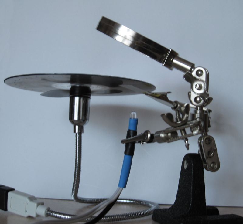
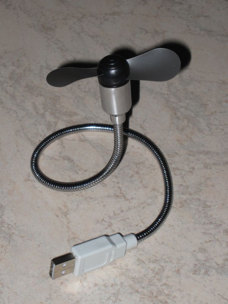 The USB fan of the famous NoName company turned up as a cooler. A pleasant moment was the dome-shaped cap with blades: the diameter of its base was 22 mm, while the diameter of the central hole of the CD was 15 mm. If you direct the fan vertically upward, then from above, almost like a gramophone, you can put a disk, and most importantly - it does not break. To improve grip, a pair of strips of double-sided tape were glued into the inner hole of the disc (see photo ). Unfortunately, the flimsy motor is clearly not designed for a 15-gram load, so it heats up pretty much in a couple of minutes of operation. With a larger cooler, such a problem should not be.
 Attention:Despite its smooth shape and light weight, a failed disk can cause some trouble. And if you go too far with the engine power, the disk may burst, and the fragments will have to not only be collected around the room, but also possibly picked out from the body. So consult common sense - the author is not responsible for any possible injuries.
Light source
Oddly enough, in 2011 it’s no easier to get a neon lamp than in 1930: they are almost never used. Fortunately, one of the LEDs that can be found in any old peripheral device, from the mouse to the printer, is quite suitable for us.
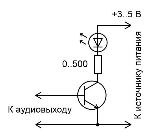 Unfortunately, the LED cannot be turned on directly to the audio output: most likely, even at the maximum volume of the glow, it will not. Therefore, you have to build the simplest amplifier on a single transistor (see diagram ). The power source can be either a pair of ordinary batteries (then the resistor can be removed) or USB (red wire - plus, black - minus; resistor from 500 Ohms or less, selected by brightness). Transistor - any npn type.
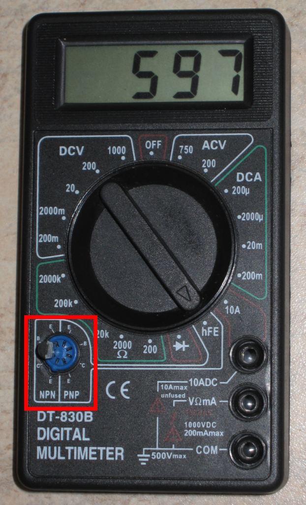
 If the transistor is picked out from some device, you can determine its type and location of the terminals usingmultimeter : try different combinations of conclusions until the device displays a number in the range of 30–1000. When this happens - spell next to the terminals to determine the location of the legs of the transistor.
If the length of the terminals allows, the circuit can be performed on twists, although, of course, it is better to solder the connections for reliability and aesthetics. In any case, bared conclusions should pull the shrink wrap or blue tape ™ to give durability.
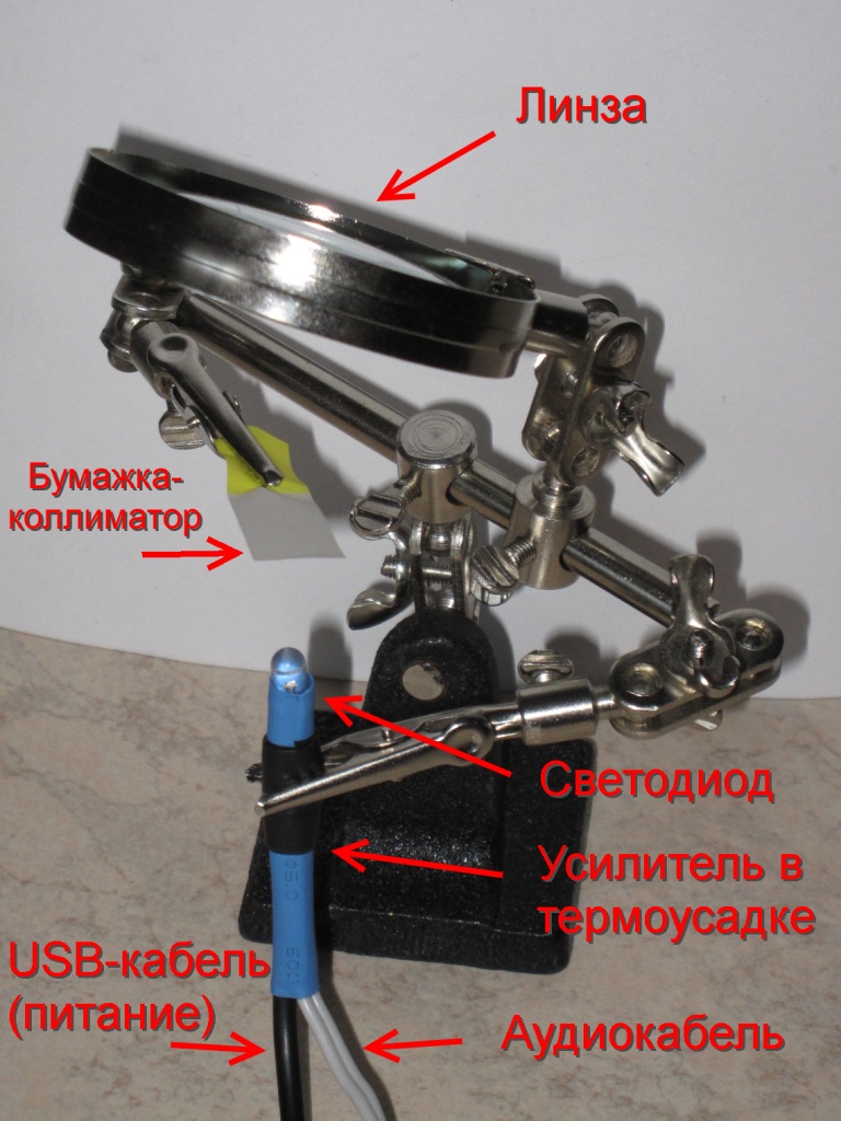
In using an LED instead of a gas lamp, there is one negative point: the semiconductor’s glow is “point-like”, and we need to highlight (evenly as possible) a 15x15 mm square. The problem is easily solved by placing a translucent piece of paper over the LED onto which a spot of light will be projected.
The assembly of the optical part looks like this: The “third hand” tool is very convenient for fixing all components in the right positions. The lens is optional, it just came in the kit. Instead of a “third hand”, you can use the surrounding objects, glue, or the help of colleagues.
Video source
The most affordable signal generator for an IT specialist is a computer sound card. We will use it. Of course, no one bothers then to record the generated file on an MP3 player and argue with friends that your one-touch iPod can play video.
To debug the system, I wrote a simple Java program that displays a 22 by 32 pixel image on a sound card. The source can be taken on pastebin , and the finished audio file is here .
In addition, there are programs that allow you to convert video files to audio signals, and vice versa, play video based on audio files. Moreover, thanks to the stereo format in one audio file, you can record both the image and the audio track. For example, this one The mp3 file turns into an excerpt from the movie "Girls":
Result

The main difficulty when viewing is synchronizing the speed of rotation of the disk with the incoming video signal. In the thirties, sync pulses and special circuits were used for this. Fans, however, were offered a much simpler and more affordable way: to brake the disk by hand. It is clear that obtaining a stable image in this way requires a certain skill ...
Well, now you can rightfully say that you assembled the TV on your knee.
UPD: added a link to avi2wav converter and NBTV viewer on the computer .
