Development of a touch battery Z-Wave switch with luminous buttons

The second year, I develop my own unique Z-Wave switch with touch buttons, which will satisfy me in terms of functionality, design and manufacturing cost.
From the very beginning, the goal was to make the 4-button switch on an 80x80 mm battery as thin as possible, the touch buttons should be large and glow as a whole when touched, and not just a small circle like everyone else. The result was a stylish thin switch that can control any device of a smart home.
During development, I solved a lot of problems in circuit design, housing design, and material selection. Particularly interesting is the creation of the touch button itself, which glows entirely, but about everything in order.
- Functional
- Case design
- PCB Development
- Examination of light diffusers
- Selection of materials of the lens
- Using
Video operation of the touch switch at the end.
Functional
The following switch features were required:
- Turn on / off the light
- Adjust the brightness of the lighting
4 buttons control 2 lighting groups. The top buttons while holding smoothly increase the brightness, with a short press turn on the light. The bottom buttons while holding down gradually reduce the brightness, with a short press turn off the light.
TODO
Make each button work in switch mode, press - on, press - off. This will allow you to control 4 groups of lighting.
Case design
I liked the idea of Basalte's 4 large touch buttons, and I decided to develop it in my own direction.
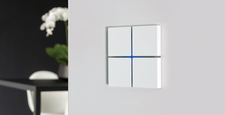
Fig. 1 - KNX Basalte switch
I wanted the button to light up as a whole when I touched it, and not a separate LED. Therefore, the body is a narrow frame with cutouts for 4 touch buttons. The locks for mounting the back cover and the recess for the installation of magnets are thought out. The mounting plate is glued to the wall on a double-sided adhesive tape and the switch itself is already attached to it with the help of magnets. It is convenient to use the switch as a portable remote and conveniently charge the battery.
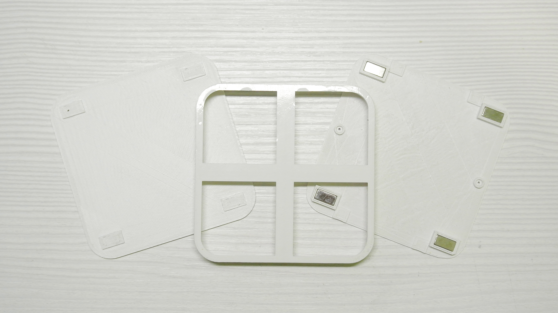
Fig. 2 - Case of the touch switch
All parts of the case are designed in Blender and printed on a 3D printer with white ABS plastic.
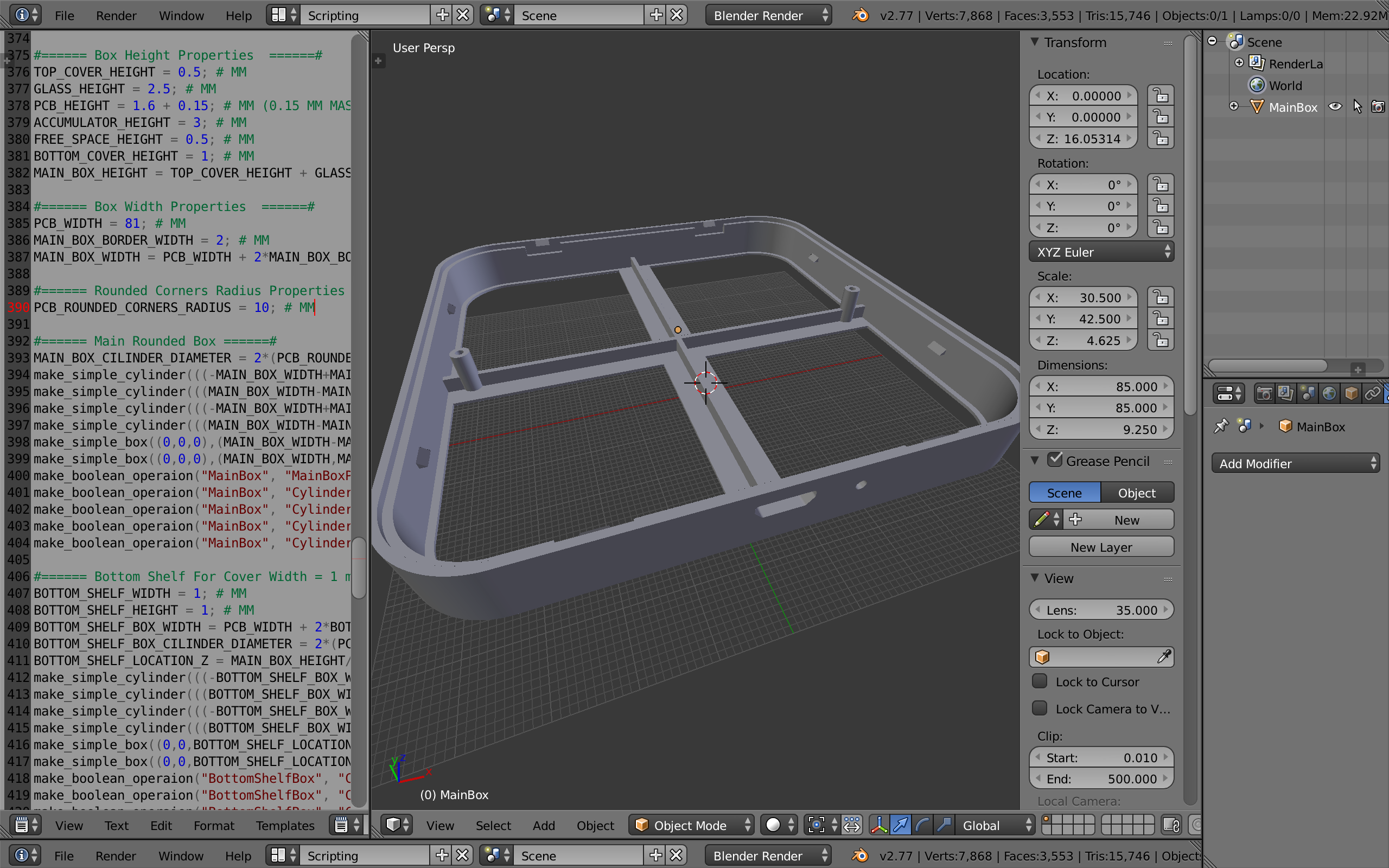
Fig. 3 - Development of the touch switch housing in Blender
PCB Development
Printed circuit board developed in Proteus. This is the second version, it uses one TTP224 sensor chip for 4 channels. In the first version 4 pieces were used. single-channel TTP223, there is no difference in operation, but when using TTP224 there are fewer components to solder.
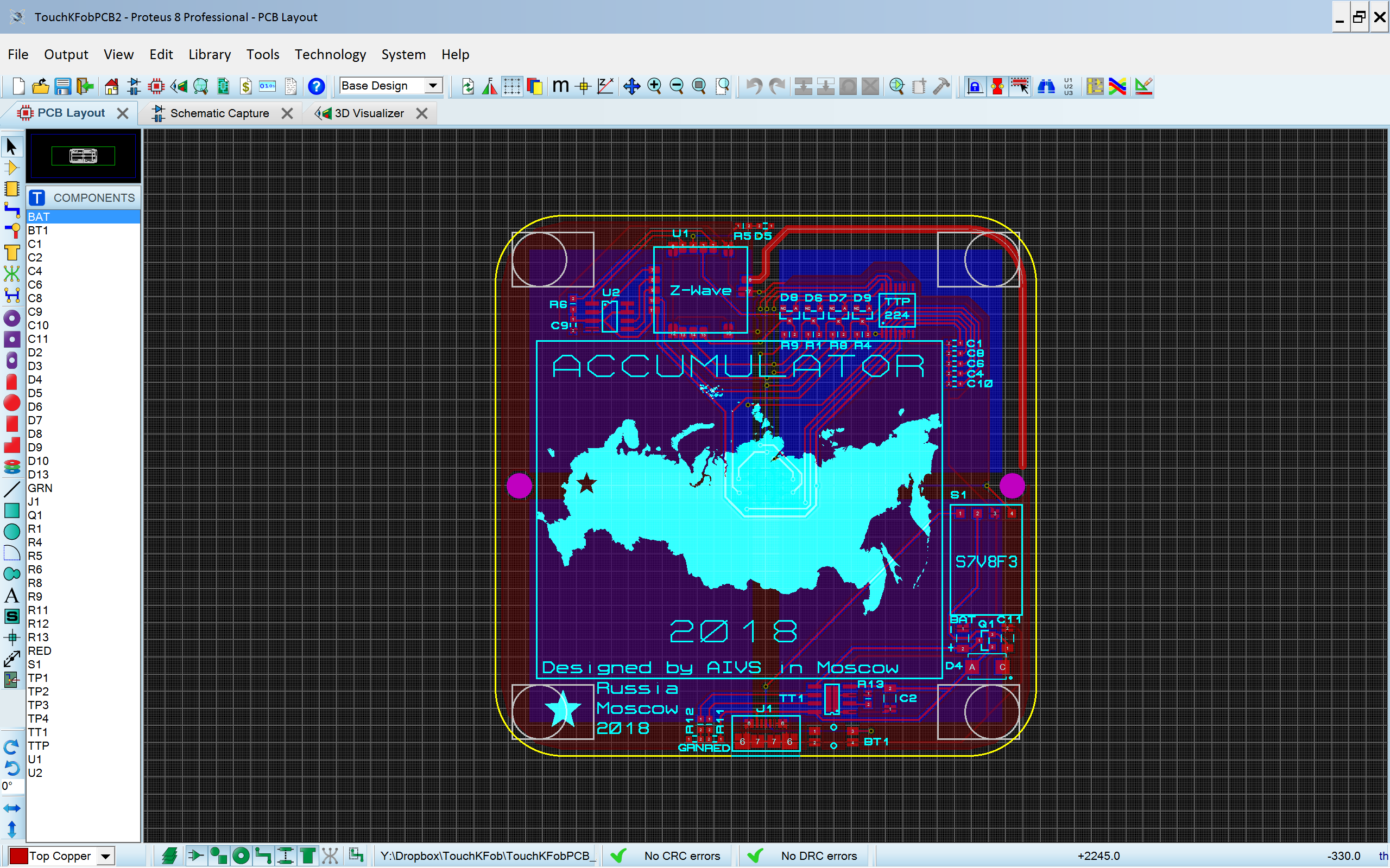
Fig. 4 - Development of the circuit board of the touch switch in Proteus
The main components on the board are:
- Z-wave radio chip
- Robiton 800mAh Battery
- 3.3V Step-Up / Step-Down Voltage Regulator S7V8F3
- TP4056 Battery Chip
- Battery to USB power switching circuit
- Calibration Button
- Chip touch buttons TTP224
The Z-Wave chip operates in the 2.7V - 3.6V range, the battery produces up to 4.7V, so I used a 3.3V up-down converter 3.3V Pololu S7V8F3. To charge the battery I used a cheap and well-known TP4056 chip, the charge current was adjusted to half the capacity of the battery 400mA. When charging is connected, the device switches to USB and the battery is quietly charged, the power switching circuit is implemented on a single transistor and a diode. When pressed, the button resets the regulator power supply and the whole circuit restarts, this is necessary for calibrating the TTP224. On the front of the board there are 4 pads of touch buttons measuring 40x40 mm and 4 LEDs. Production ordered by Seeedstudio, the quality and price are very satisfied.
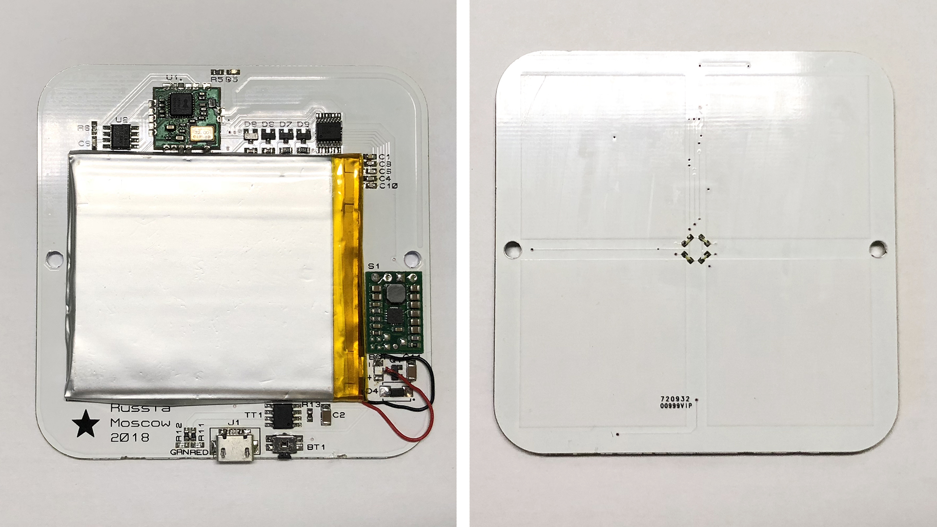
Fig. 5 - Touch Switch Board
The most important component in the touch switch is the touch button controller. I tested 3 controllers and each had both advantages and disadvantages. Test results of the 3 controllers of the touch buttons:
TTP224
Pros: Cheap, on the one side of the PCB there may be sensor pads, on the reverse side other components, but the sensitivity is greatly reduced. Setting the output signal: high / low level, setting the button mode: switch / on. 4 channels.
Minuses:If there are tracks on the back of the touch pad, it does not work through plexiglas more than 3 mm and even worse if a film is stuck on the glass, does not react to a small touch, only pressing the entire pad of the finger, even with the configured maximum sensitivity (Cs = 1pF, range 0 -50pF, the smaller, the more sensitive).
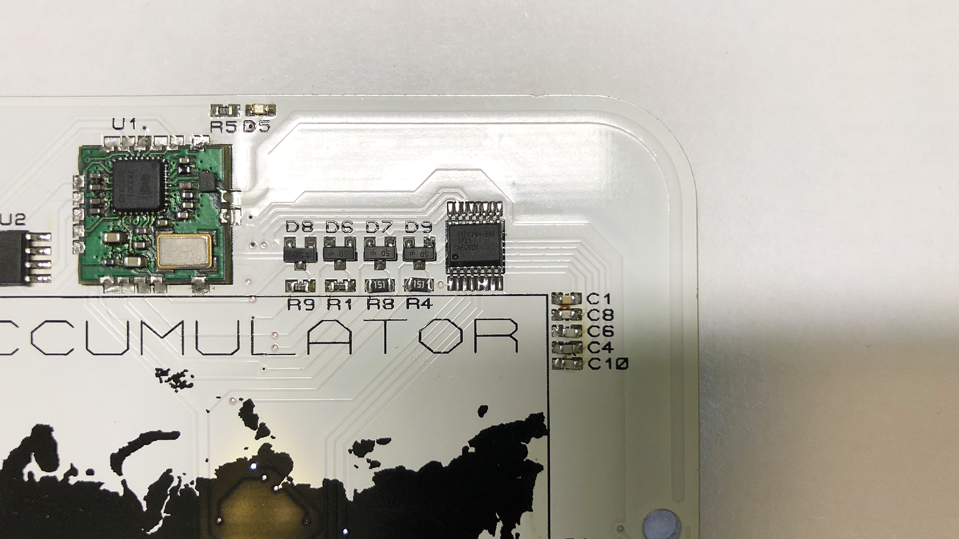
Fig. 6 - TTP224 on the finished
AT42QT1011 board
Pros: Responds to a slight touch through 3 mm (and more) plexiglass, if you adjust the sensitivity at an average level (Cs = 22nF, range 2-50nF, the more, the more sensitive). Automatically adjusts to the glass thickness.
Minuses:Under the touch pad there should be no tracks, no power, no ground, otherwise the sensitivity decreases. Exit only high level. 1 channel only.
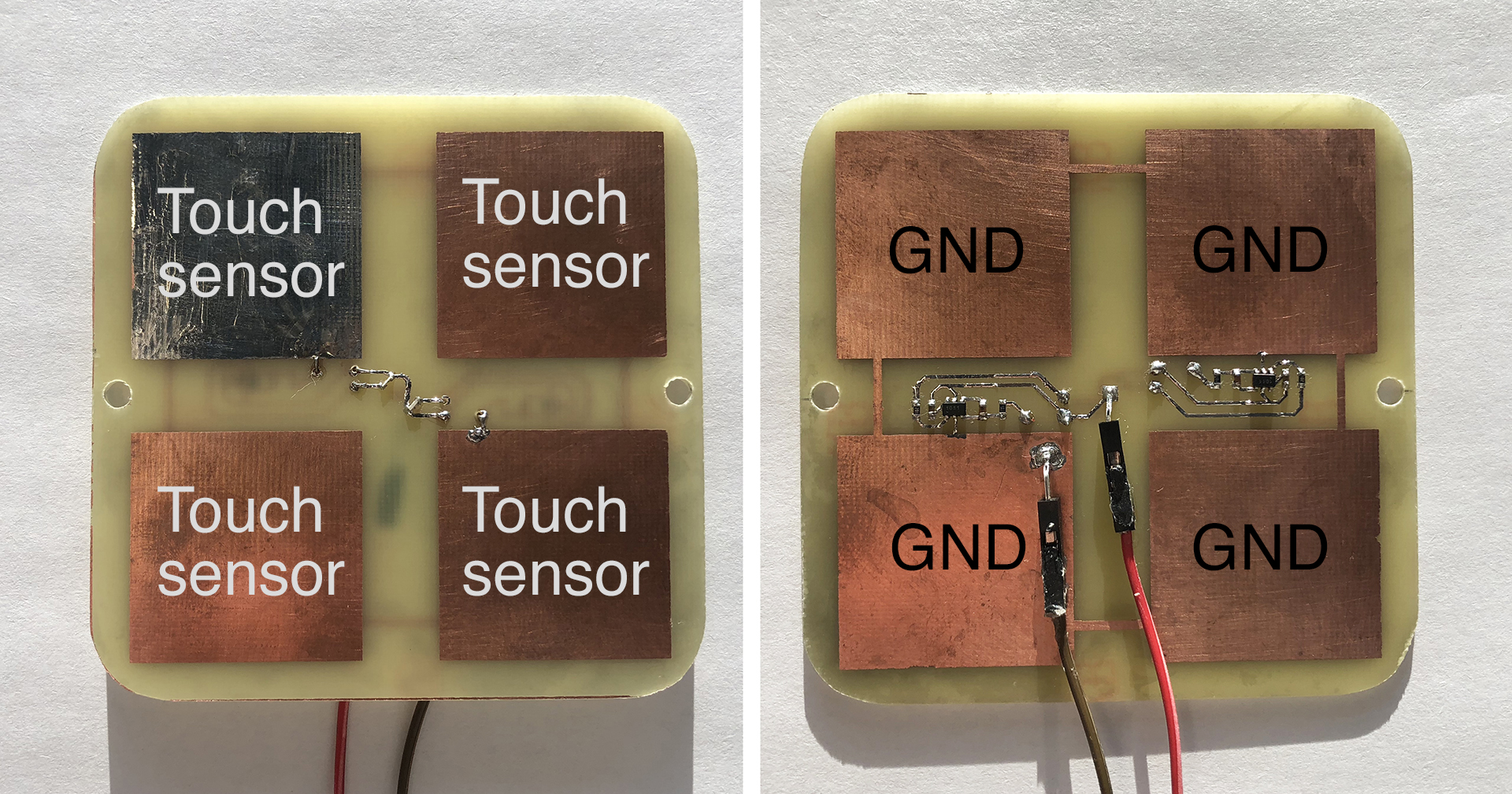
Fig. 7 - AT42QT1011
MTCH105 test board
Pros: Reacts to a slight touch through 3 mm (or more) plexiglass. Protection against interference using the ground around and under the sensor pad, automatically adjusts to the glass thickness. 5 channels.
Minuses: Long reacts to pressing and for a long time understands that the finger was released, about 0.5 seconds. If you hold your finger on the sensor pad, then after 9 seconds the LED turns off, calibration takes place. The touch pad needs to be covered with earth on all sides, including under the pad, otherwise it works at any point where the PCB touches.

Fig. 8 - MTCH105 on the breadboard
I chose TTP224 (4 channels), because on one PCB on one side you can place all the components, and on the other side - the sensor pads. I sacrificed sensitivity, through 3 mm plexiglass works if you touch the whole pad with your finger, although this can be interpreted as protection against accidental touching :). If there are no tracks under the sensor pad, then it reacts through 4 mm plexiglass at the slightest touch.
TODO
To produce a touch switch with two textolites, the first for touch pads, the second for all components. Add vibrator and buzer. Implement the function of a weak backlight when the built-in motion sensor is triggered.
Examination of light diffusers
The task was to uniformly illuminate the 40x40mm pad, which the finger touches. Due to the limitations of the size of the case, it turned out to push only one LED for each pad.
I studied the device of several touch switches: Livolo, Vitrum, HTTM touch button. Each used its own approach to uniform light scattering.
Vitrum
Italian Z-Wave switch with expensive decorative glass. The reflector-diffuser is implemented as follows: on a transparent plexiglass, a rim is painted with reflective paint, highlighted from the side by a single LED. On the LED side, the paint is less applied, thereby achieving a uniform glow all over the rim. Top mounted decorative glass.
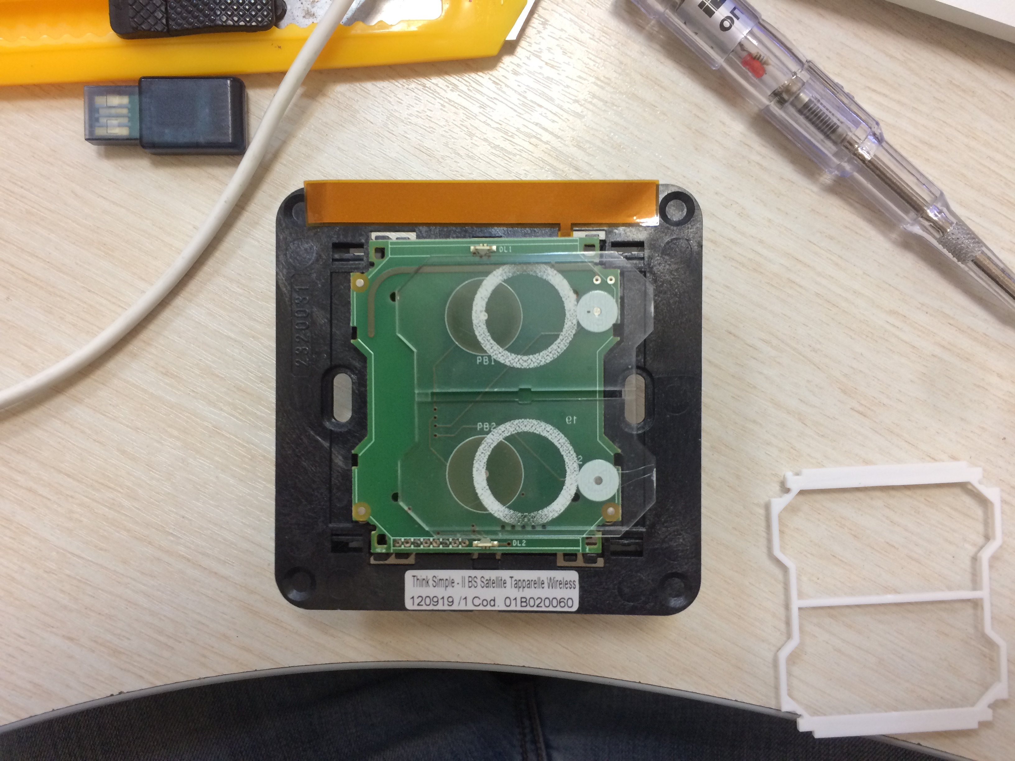
Fig. 9 - Pattern of reflective rim on plexiglass
Livolo
Budget Chinese touch switch. There are 2 LEDs on the board: red and blue, the LEDs shine inside the opaque translucent plastic, due to frequent light refractions inside, a uniform glow of the entire surface is obtained, a reflective paint is applied on the textolite.
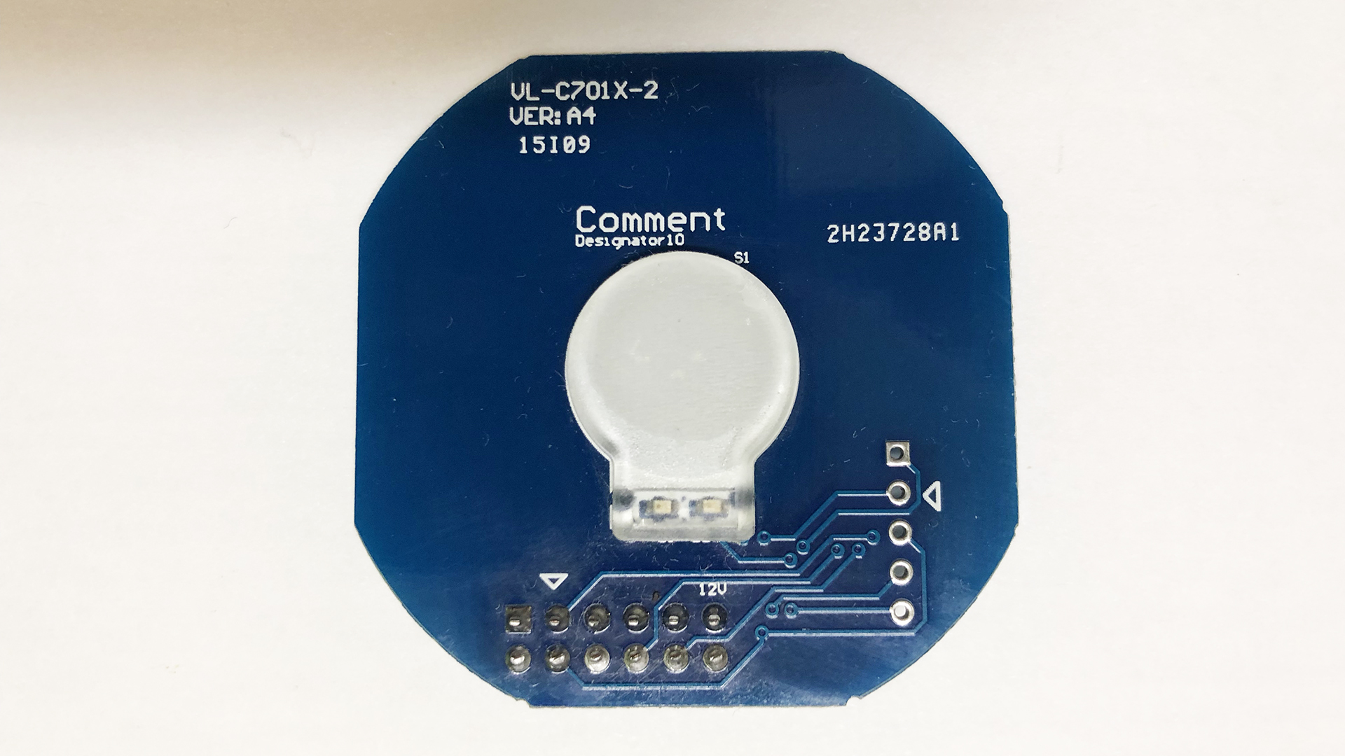
Fig. 10 - Touch switch part Livolo
HTTM - HelTec Touch Model
Ready touch module with Noname microcircuit. The reflector-diffuser consists of 3 parts: a PCB with a tinned pad, plexiglass for the backlight with a lot of microholes, a white, muddy film.
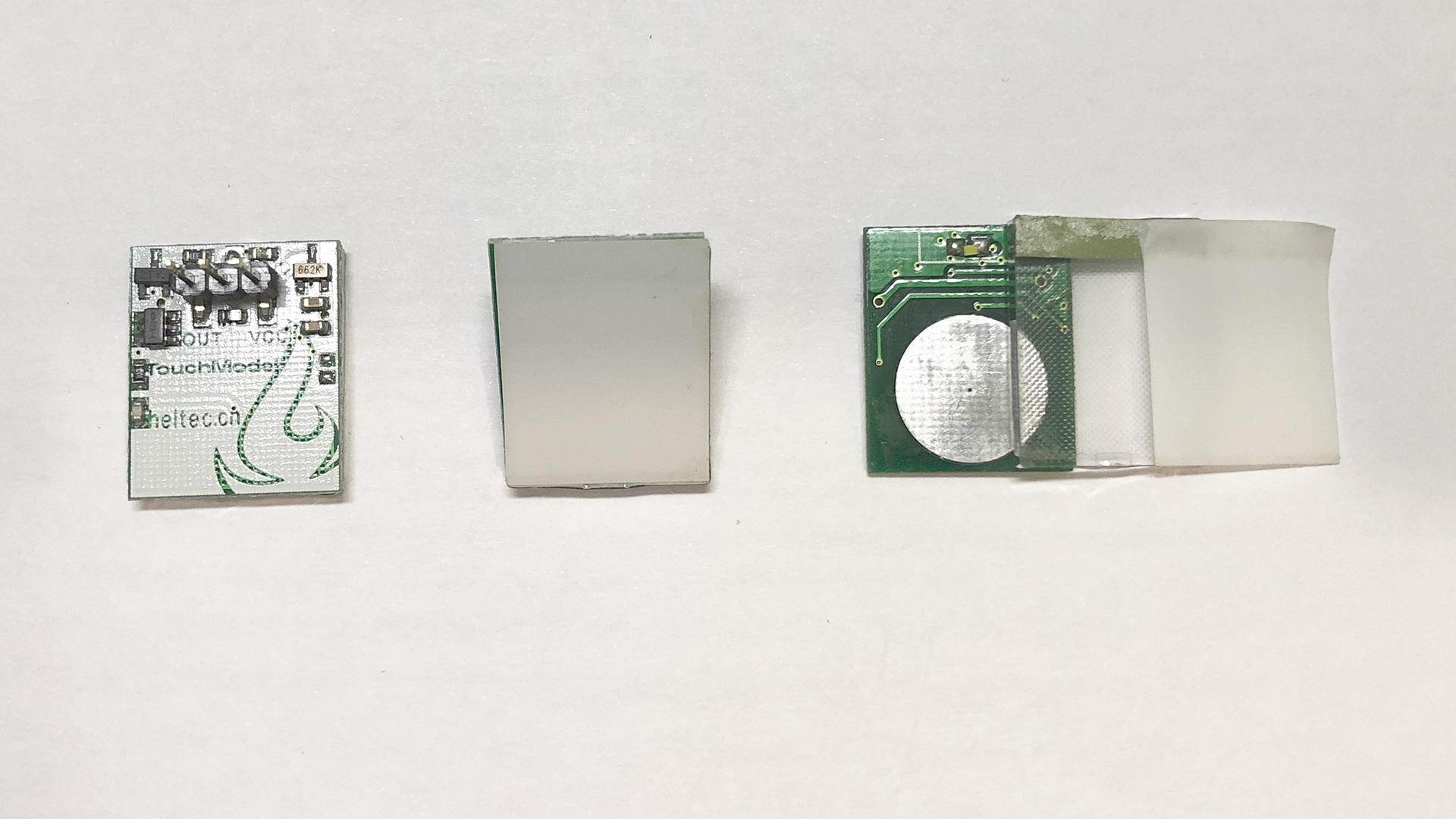
Fig. 10 - Disassembled HTTM touch module
Selection of materials of the lens
Frosted plexiglass diffuser.
Usual clear 3 mm plexiglass was treated with fine sandpaper on both sides to give a dullness. This plexiglass evenly scatters light across the surface. The thickness of the material allows you to comfortably work with any sensor chip. But on the surface are visible minor scratches, which affects the aesthetic appearance.
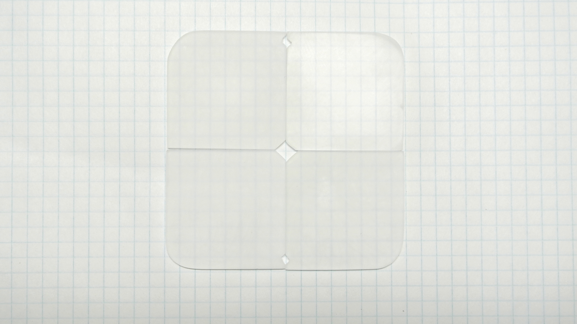
Fig. 11 - Matte Plexiglas Plexiglass
diffuser for edge lighting (LGP) and milk Plexiglas
I used 2 different plexiglas 2 mm thick, a sandwich of two elements turned out 4 mm. The lower plexiglass for the edge illumination, thanks to the white points applied, uniformly diffuses the light over the entire surface. The upper milk plexiglass gives a soft glow and a beautiful look, while the brightness is noticeably lower and the switch weight increases.
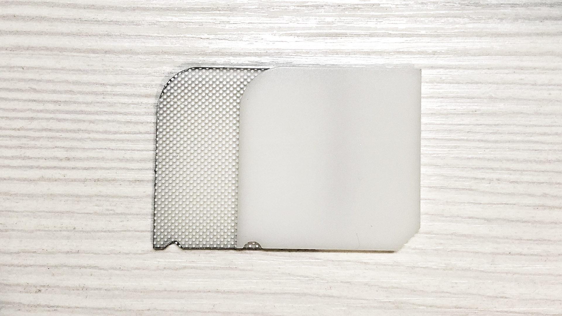
Fig. 12 - Plexiglas for edge lighting and opal plexiglass
Ledison lightbox panel
The Russian company Ledison provided a lightbox panel consisting of 3 components to the test: a reflective backing, a special light-scattering 3 mm plexiglass (seemingly transparent, but a grain structure is visible inside), a transparent protective film. I replaced the top film with a matte Oracal 8500 and it turned out a good dispersion. But when working with a switch, the film does not look solid, it can get scratched and it is difficult to glue it without bubbles.
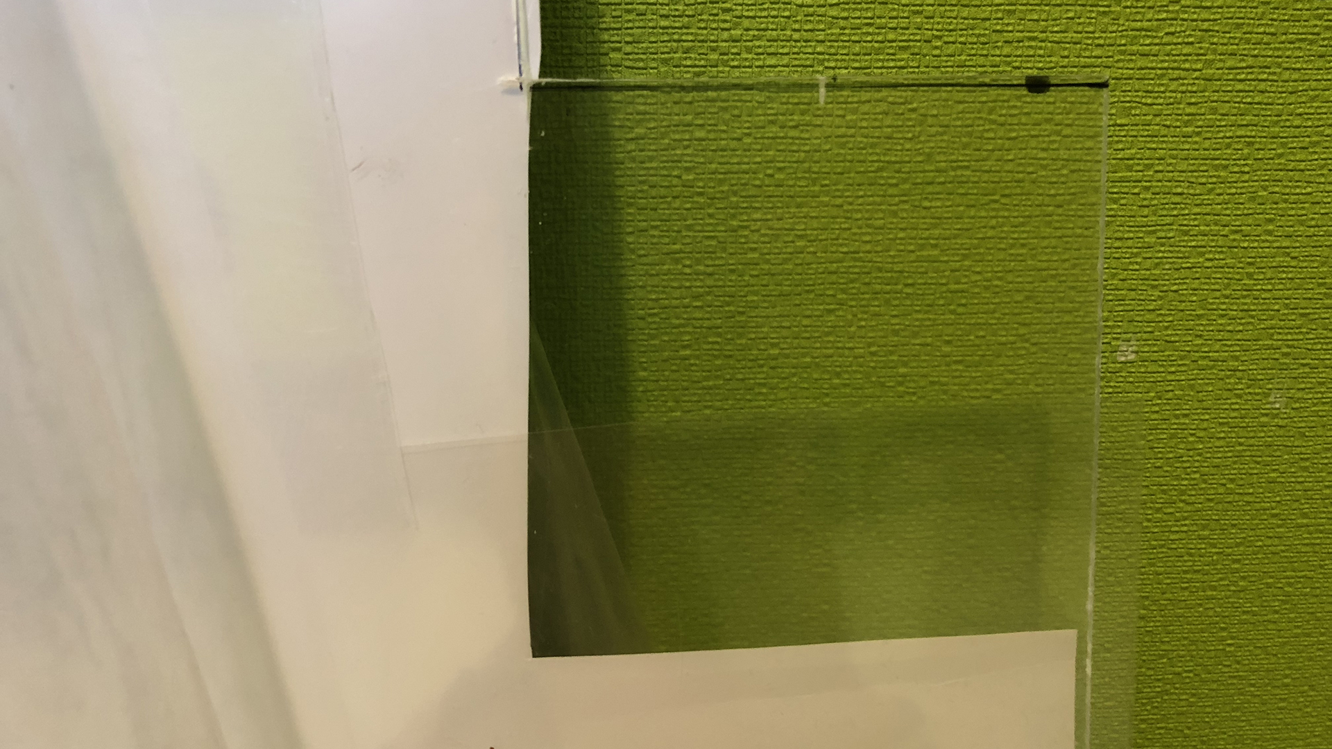
Fig. 13 - Ledison Lightbox Sandwich
After all the tests in the switch, I applied a Ledison reflective backing and made them matte. At the moment, this is the best option for me, and evenly dissipates, and the brightness is not reduced, and the thickness is suitable.
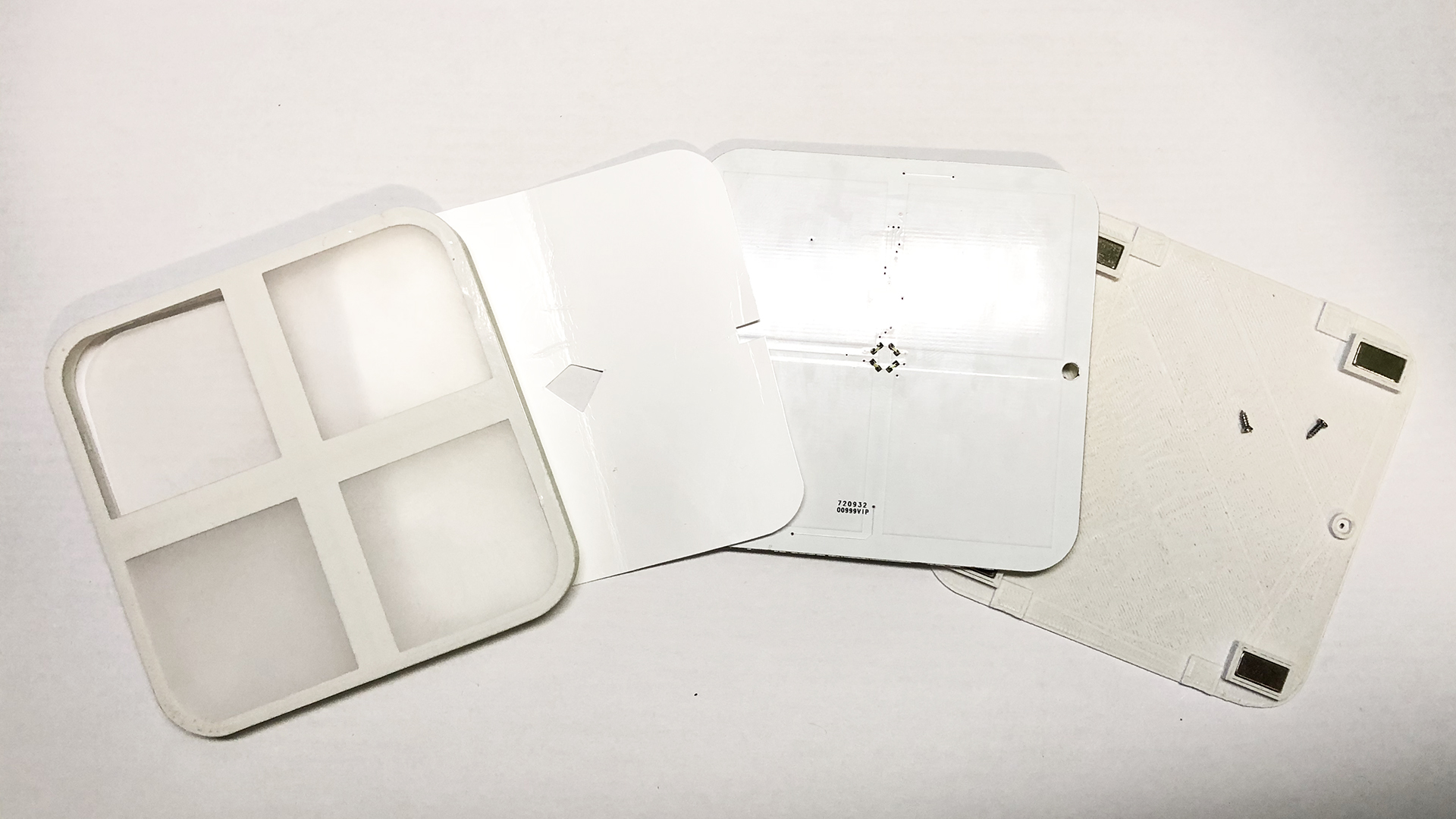
Fig. 14 - Case, board and diffuser
Using
I made the first test versions of the switches 2 years ago and I already have experience of using them, one is installed near the bathroom at a height of 120 cm and is convenient for children, the second is located near the bed and controls the nightlight, chandelier and LED lighting. Because All buttons are separated by a cross-hair, they are easy to grope in the dark and press the desired one. Light feedback says exactly which button is pressed. Compared with the pushbutton switches minus not found.
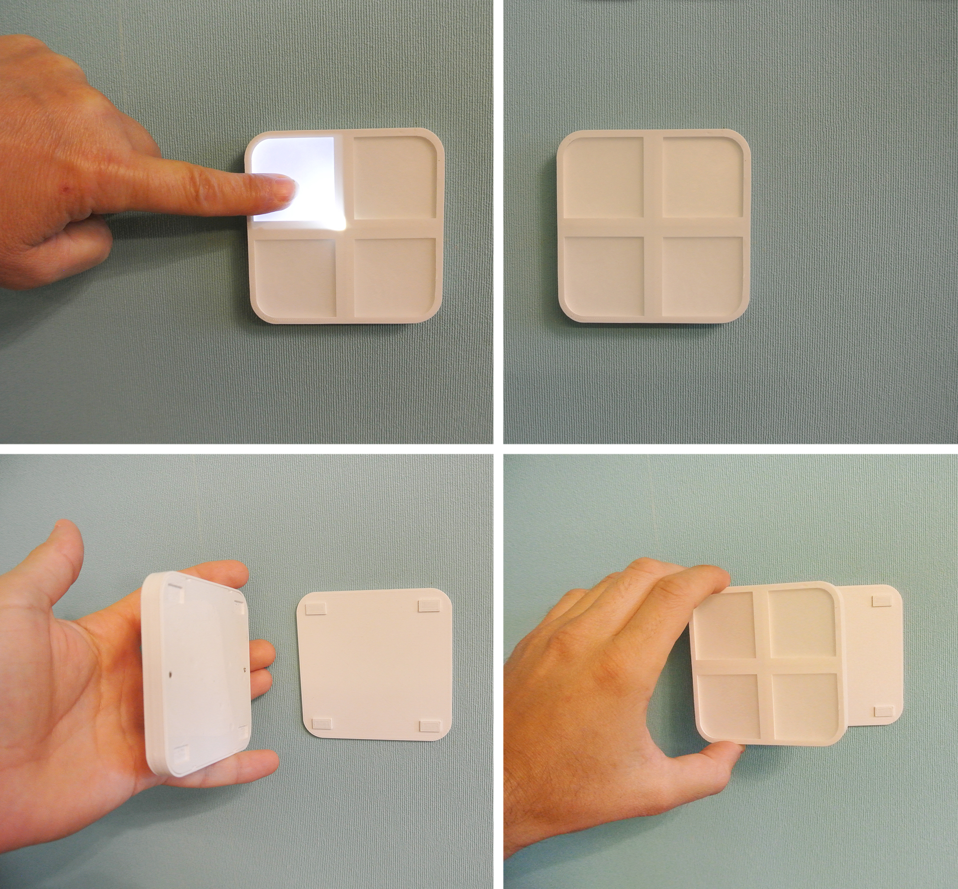
Fig. 15 - The touch switch on the battery in the business.
I noticed a pleasant side effect, the switch near the bed can be used to illuminate the drawer, if you press the bottom buttons.
PS
At the moment, the Z-Wave chip uses firmware from a 4-x button keyfob Z-Wave.Me Key Fob, it’s convenient that it is already ready and well-working, it’s inconvenient that not all functions are there that you want. The only unresolved issue is the illumination of the corners in the center, you need to cover with foil film, but for now I think it is much better to sculpt the foil on the case inside or on plexiglass.
Further plans to go to the freely programmable Z-Uno Module for the implementation of all software hoteles.