RGB lamp
Reflecting on a gift for a girl on March 8, I remembered the project of an LED RGB lamp, which it was decided to implement. Moreover, everything necessary for this was at hand. But to make the present more interesting, I added control using an optical infrared sensor, which made the lamp handling original and also did not spoil the design with buttons.
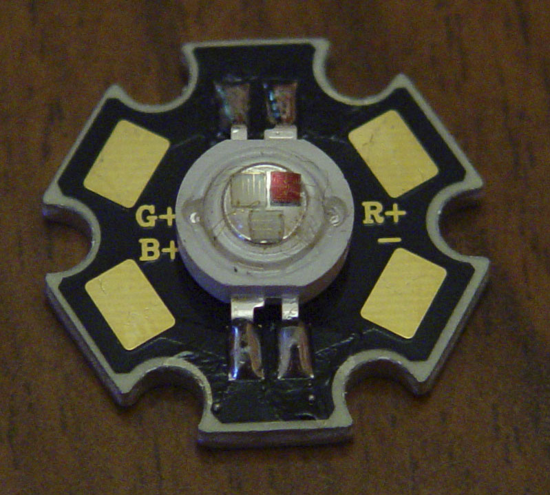
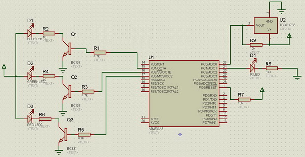
An RGB LED is essentially 3 LEDs of different colors in one housing. In my case, an LED with a common anode and with 3 cathodes, one for each diode, although the designations on the diode are the opposite.
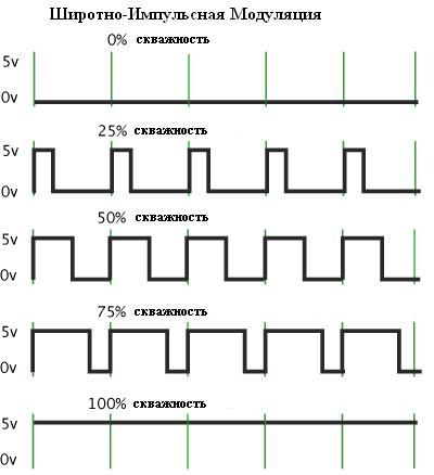
In order to get different colors of the glow of our LED, each diode must be turned on using PWM's (pulse-width modulation), otherwise the LEDs will light up to the maximum, which will ultimately give us a white color.
PWM is a pulse signal of constant frequency and variable duty cycle. Using the duty cycle, you can change the average voltage at the PWM output, as a result of which the brightness of a particular LED will change. In our case, the PWM frequency will be 1 kHz. To generate a PWM signal of variable duty cycle, we need a microcontroller.
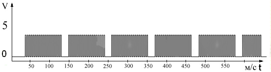
Optical sensor - consists of an IR LED and an IR receiver. The LED and the receiver will be directed upward, when you hold your hand over the sensor, the light will be reflected by hand and will be received by the receiver. Since the RGB LED has strong spurious IR radiation, it is necessary to protect the sensor from false alarms. To solve this problem, the TSOP1738 receiver is used. It provides for triggering only on a modulated signal at a carrier frequency of 38 kHz, but if the modulation pulses will go on continuously for more than 1 second, the receiver will recognize them as interference and will not respond to them. It was experimentally revealed that in order for the receiver not to cut the signal, it must be interrupted every 100ms for 20ms.
A signal like this should go to the LED.
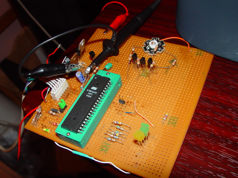
Microcontroller (mk) is a microcircuit designed to control electronic devices. To implement the control, you must write a program and flash it in microns using the programmer. In the final version of the device, I used ATMEGA8, and for the first experiments I took ATMEGA32, because for it I had a debug board on which everything could be quickly assembled.
In ATMEGA8 - 3 timers / counters are provided, their essence is that they can count the clocks with the selected frequency, which depends on the clock frequency mk. Upon reaching a certain value, an interrupt occurs, on which the interrupt code will be executed.
Timer / Counter 0
This 8-bit timer means that it can read up to 255 clock cycles, after which it will be reset. This timer does not have a hardware PWM generator, with its help, modulation for the IR LED will be organized programmatically.
Timer / counter 1
Timer / counter 1 - 16 bit, it counts up to 65 535 clock cycles. He has 2 hardware PWM generators, which will be used to control 2 out of 3 diodes.
The timer / counter 2 is
also 8 bit and has 1 PWM generator that will control the 3rd diode.
As a programmer, I used the USBAsp USB programmer .
To assemble it, you need to flash one micron, so there are simpler options that really require LPT or COM ports.
I wrote the program in C using CodeVisionAVR and ImageCraft7. First of all, you need to set timers 1 and 2 to PWM mode at a frequency of 1 kHz. Then set the interrupt by timer 0, with a sufficient frequency to process the interrupt code, in my case the interrupt call frequency was 148 kHz. It is also necessary to establish an interrupt from an external source, it is necessary to respond to the signal of the receiver.
Upon interruption from the receiver, the LED will flash white for 100ms to indicate operation, and add 1 to the mode variable, in the main cycle, a certain mode will turn on depending on the variable. The change of modes is implemented in the cycle by changing the duty cycle with a delay at each iteration.
Assembly
First of all, the concept.
Power is supplied from the power supply, the output voltage is 5 volts, current 1A.
I bred the board in the Sprint Layout 5 program. The
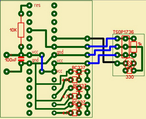
board is divided into the main and the optical sensor board. This is done so that the sensor can be conveniently positioned, the blue line on the main board is a jumper, the other blue and black lines are wires.
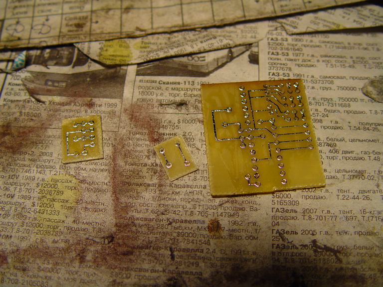
Made by laser iron .
I note that it is better to use an iron with a steam generator, thanks to a couple of paper it is easier to move away from the board.
The center board was not used in the final device.
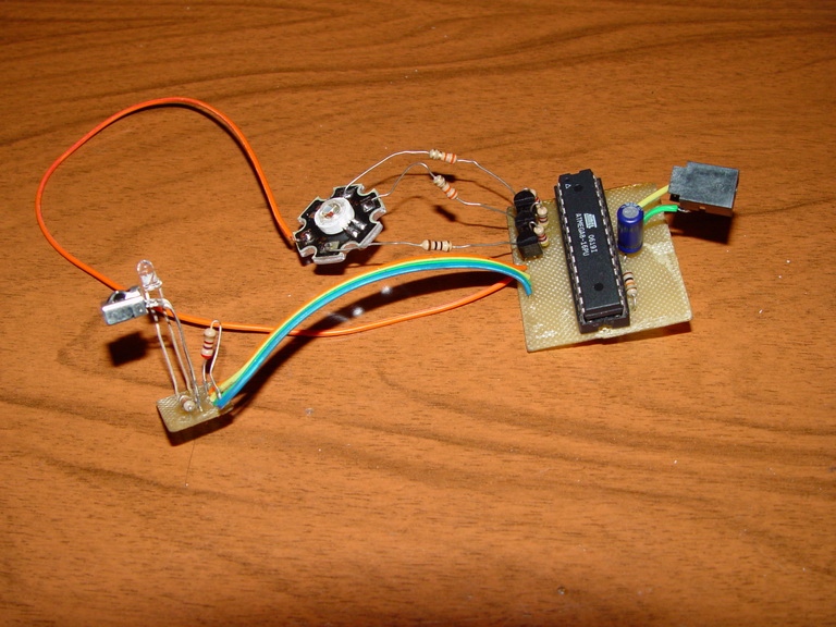
Pre-assembly.
Lamp
Assembly
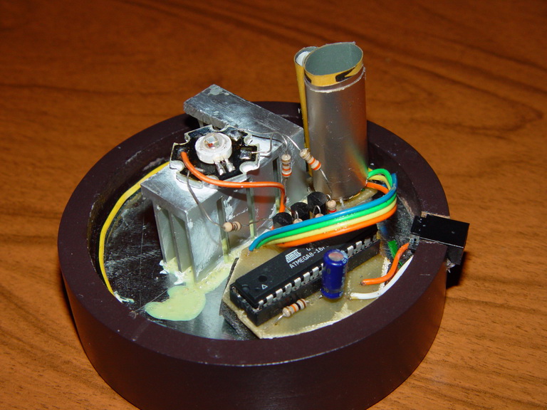
Since the glass itself turned out to be almost mirrored inside, I had to isolate the receiver and the IR LED using sandpaper and foil, but I would have to isolate it in any case, otherwise there would be illumination. The radiator is required to install, the diode will be very hot and just overheat without the radiator, in addition, in my firmware the diode works at 70% of maximum power. In the white light mode, the temperature rose to 53 degrees for an hour and did not grow anymore, which is quite acceptable.
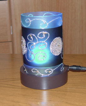
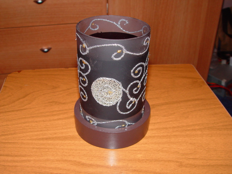
Final result
To implement the plan, the following was required:
- RGB LED, I took a power of 3 watts.
- Microcontroller ATMEGA 8 - for others, you will have to modify the firmware.
- Socket for ATMEGA 8
- IR receiver - e.g. TSOP1736
- IR LED, e.g. FYL 3014ir
- 3 transistors BC337
- 0.1 uF capacitor
- Resistors:
- 10 ohms - 2 pieces
- 3 Ohm - 1 piece
- 1 Kom - 1 piece
- 10Kom - 1 pieces
- 330 Ohm - 1 piece
- 4.7Kom - 3 pieces
- AVR programmer
- Switching power supply - output voltage 5 volts, current 1A.
- Actually the lamp itself
- Wires, textolite, radiator, thermal grease, etc.
Some definitions were taken from Wikipedia.
Source, firmware and wiring file.
Upd : If you want to assemble a lamp for this post, then do not forget to look at the source, the fuses are stitched at 8 MHz. Since μ is clocked from the internal resonator, and its error is quite high and can be 10%, most likely you will need to adjust the modulation of the IR LED in the line TCNT0 = 0xCA; so that its frequency matches the frequency of the receiver. Archive wiring file for Sprint Layout 5.0.