Centralized remote control control of lighting sources TsPKIO-2D Rotor
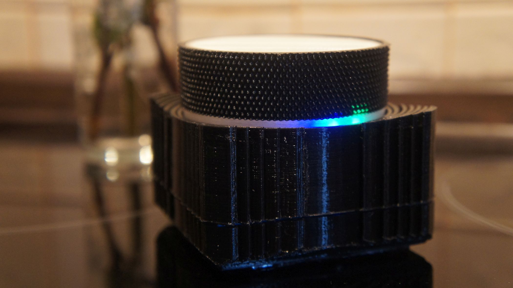
Sorry, I have not had fun with naming for a long time, as well as with the periphery for home automation. Specifically, this thing - the remote control light - turned out, because I wanted something with an interface like "click-twist-click", and not with the usual scattering of buttons. The wow effect is not achieved: the home ones do not notice the remote at close range, but at least I have closed the gestalt.
Short TK:
1) Control of three lighting groups in the kitchen
2) Control of three lighting groups in a room
3) Control of all light sources at the same time
4) Reasonable battery life (from a week)
5) Compatibility with Livolo, SC2260, EV1527 coding
Total, no further you need to read if you do not like Arduino, Livolo switches and Chinese radio sockets. Because the first is the basis for the console, and the second and third is the periphery.
Concept
The control logic seemed to me the following:
- Clicking on the "Krutilka" switches the zones of the lighting group around the ring (the kitchen - the room - everything).
- Turning the knob, depending on the direction of rotation, sequentially turns on or off the lighting of the selected group.
- The mode of operation (selected group) is displayed by an unobtrusive LED display.
Since I have radio control on the most despised option, without protection from interference and feedback, a small trick is also provided in case of a miss of a trigger.
If turning the knob does not lead to the desired result, then the combined pressing and turning in the opposite direction allows you to skip the command. Then the command can be repeated as usual.
That is, if I turned the knob clockwise, and the main light did not come on, then I can press the knob, turn it counterclockwise, and then release and turn it clockwise again to repeat the switch.
Why so hard? Then, aside from awkward protocols, I also have awkward peripherals. For example, Livolo radio-controlled light switches and radio relays, in which the same command to turn on and off, along with the usual radio rosettes, in which the commands to turn on and off are separate.
The team skip trick allows you to creatively beat non-power (non-power), without breaking the overall illumination scheme. In addition, skipping a command allows you to jump over light sources that are not required to be turned on or off.
And, of course, to understand what is happening with the console at all, it has a separate indicator, which is lit when a command is sent.
If the console does not touch for some time (configured in the code), then the controller goes to sleep. However, he does not save the last state, and when he wakes up by pressing the handle, he begins his life from scratch.
It's not a mistake. Again, I have switches without feedback, and the console is not physically able to obtain information about the current state of each controlled peripheral device.
Therefore, immediately after waking up, turning the knob begins to either turn on or turn off the light from scratch.
First approach
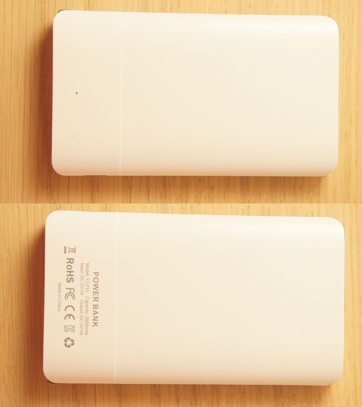
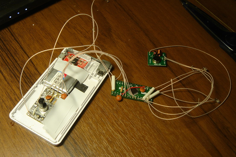
The visual concept of the “box with a twist” view required, as you might guess, two things: boxes and twisters. In the first version, the role of the box was played by a thin powerbank, the use of which solved two problems at once: I had a case and a battery charging circuit, and already with a connector. The battery itself, of course, had to be replaced with a more compact one, otherwise the filling would not fit.
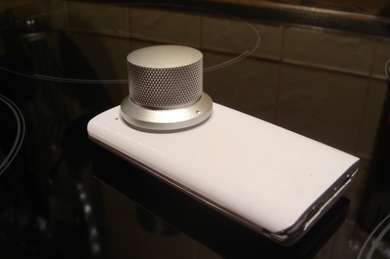
With the twister came out intricately. In the course of the search, I found out that the nicer the potentiometer knob and the bigger it is, the closer its gram cost is to the gram gold value. Therefore, I acquired a pen that minimally suited me for aesthetic properties.

The control part was the result of an experiment with ATmega328P and a natural continuation of the storyline set by the already existing home automation (on the same Arduino and primitive radio protocols).
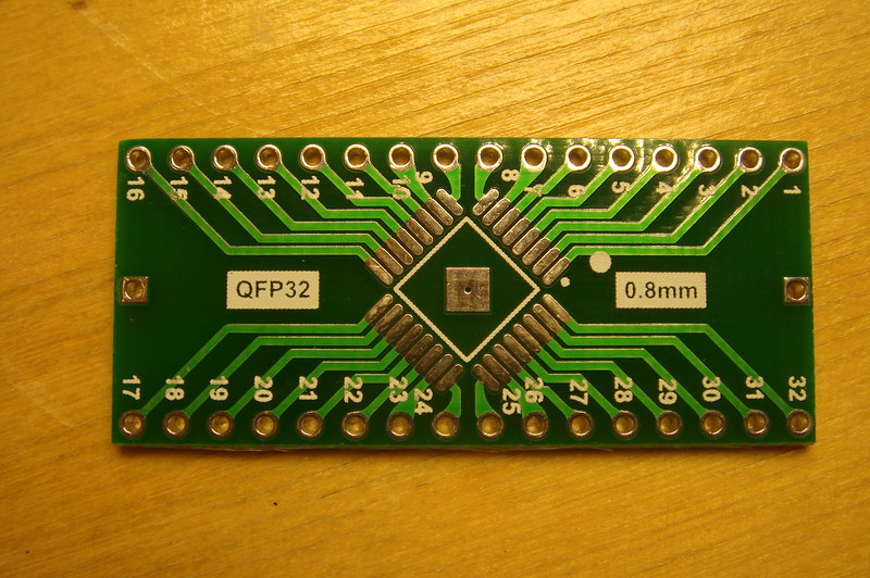
I did not buy a lot of the above-mentioned controllers and conditionally mock-up (in fact, the adapter from the small case to the large step) boards, in order to try to make a low-budget version of the Arduino with the minimum (but reasonable) number of elements.
The experiment turned out to be successful, and the controller configured for the Arduino environment quite successfully blinked with an LED after swallowing the classic Blink. Well, then according to the principle “doris owl”, I added an encoder (with a button), three LEDs, and a conventional transmitter with amplitude modulation on a carrier 433.92 MHz to the resulting board.
To place all the elements in a small case, I had to suffer a little, but the remote still worked. And although, it would seem, the problem was solved, I wanted more - the original case.
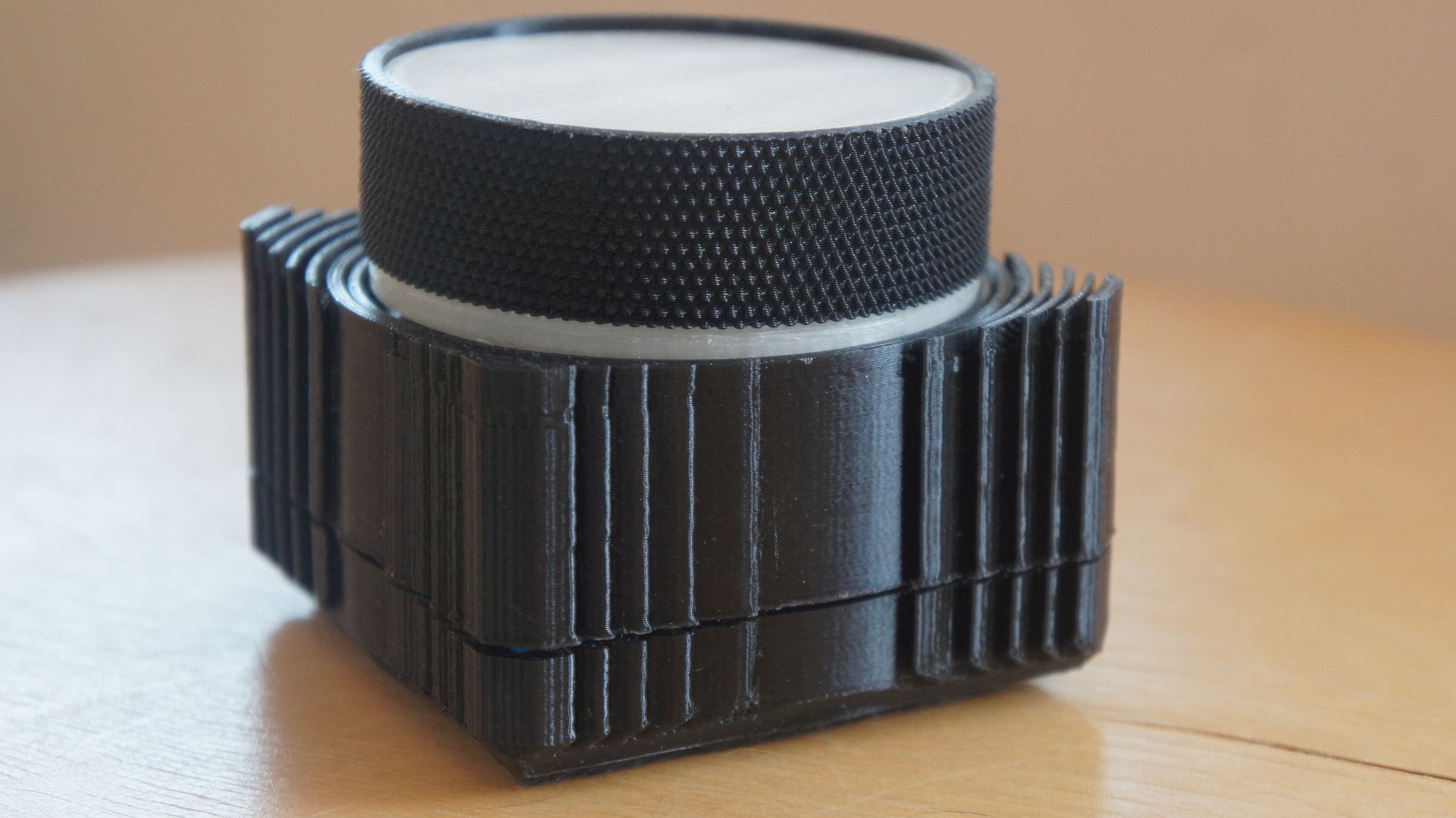
Second approach
Actually, the first version (complaining) in appearance was a group of comrades smashed to smithereens, so I postponed it indefinitely. But did not disassemble: sorry.
But when a 3D printer appeared, he promised himself one day to make the very original case and thus close the issue with the remote control.
I don’t know if it turned out badly or well — I don’t really know how to evaluate my pieces. But on 3DToday, the team is more welcoming than on MySKU (which I don’t complain about is not a gift myself), and they rated the body higher than I did.
But having complete freedom of action, I refused the frail and unintelligible Chinese batteries, and took the good old 18650 power source. And, as it is easy to see, it is its dimensions that largely determine the dimensions of the whole case.
The very same body I began to make modular, consisting of many parts, which allowed to reprint only individual (erroneous or not too optimal) elements, and not the whole product.
Another point is that I really do not like to make cutouts for connectors, which I really do not get. Therefore, in the supply chain there is another trick known for hedgehog Evelyn : wireless charging.
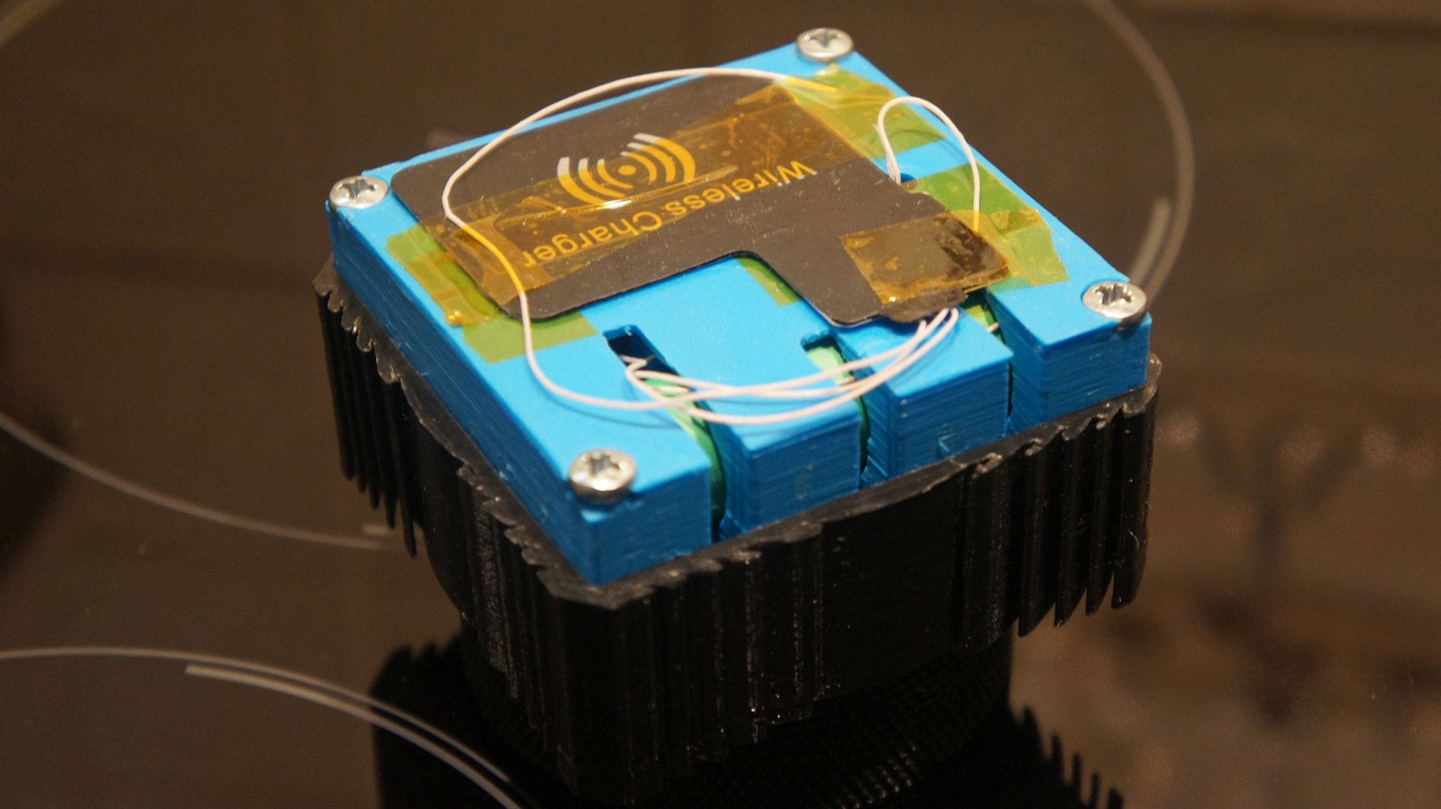
I had another receiver in my storeroom, which I immediately let go of business.
Finally, the last trick is pretty obvious, but still: so that the console does not crawl on the table, I stuck a piece of non-slip car mat to the bottom. And in the end, this thing is an absolute monolith, although rearranging it to another place is also not a problem.
What you need to repeat
Piece of iron
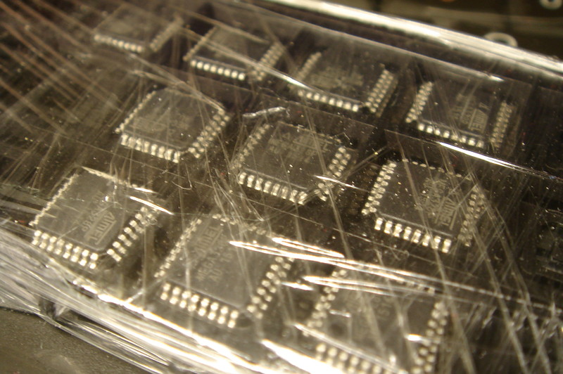
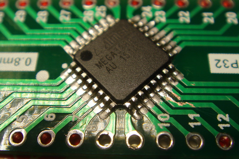
1) ATmega328P controller - 1 pc. (in my TQFP package, but any one can be used)
2) 10 kΩ resistor - 5 pcs. (4 for suppressing encoder chatter, 1 for controller)
3) Resistor 100 Ohm - 3 pcs.
4) Ceramic capacitors 0.1 μF - 4 pcs. (on the controller and encoder chatter suppression)
5) Pressure encoder (valcoder) - 1 pc. (I have PEC12-4220F-S0024 )
6) LEDs - 3 pcs. (3 mm diameter)
7) Lithium battery charging board - 1 pc. (from the powerbank that came to hand, in theory, any one with automatic switching on under load)
8) Qi wireless charging receiver - 1 pc.
9) Transmitter with amplitude modulation at 433 MHz - 1 pc. ( like this )
10) Some fiberglass for the encoder board
11) 3D printer
12) Suitable plastic (I printed PLA)
13) Screws M4x30 - 4 pcs.
In general, the number of components can be reduced. For example, in a completely minimal version, the controller does not require a strapping at all, although I decided to follow the advice of Nick Gammon and did not regret a pair of capacitors and a resistor.
Similarly, you can not bother with the hardware suppression of contact bounce, and try to do software. Then you can cross out four more resistors and a pair of capacitors.
Alternatively, you can use a ready-made Arduino board, like the Pro Mini, but in this case I cannot guarantee a low level of energy consumption, and you have to conjure it yourself. At the same time it is necessary to correct the case.
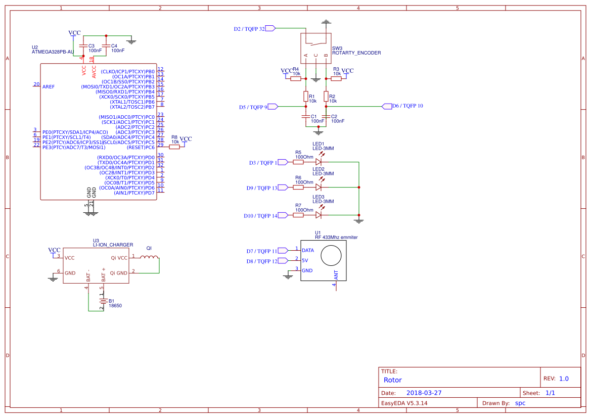
Scheme:
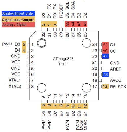
For reference, the ATmega328p pinout in the TQFP-32 package from Hobby Electronics :
I drew a small board for my encoder:
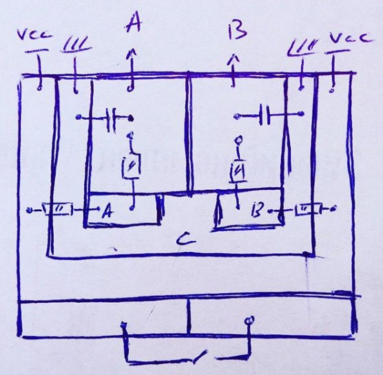
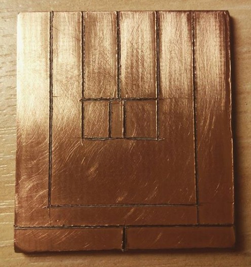
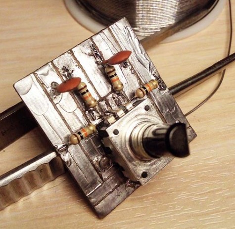
For good, it would have to be drilled to mount the encoder, or press it with the belly to the board (taking care of isolation so that there is no short circuit ) so that the encoder was mounted a) more or less evenly and b) did not stagger. Historically, I have the second option.
For the case, it is important that the board height with details, excluding the encoder, be no more (or not much more) than 5 mm.
If you don’t have a ready-made Arduino board, then in order for it to work, you need to first write the Arduino bootloader to the ATmega328P controller.
Для этого необходимо, во-первых, добавить в среду Arduino описание контроллера. Для этого идем на официальный сайт Arduino и скачиваем оттуда подходящий для установленной у вас версии среды архив описаний (для 1.6, для 1.5, для 1.0).
Содержимое архива следует извлечь в папку hardware папки среды Arduino. В дальнейшем я описываю происходящее на примере среды 1.0.3, которой пока пользуюсь.
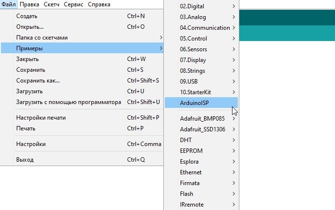
Когда описания скопированы, следует запустить Arduino и загрузить скетч программатора в Arduino, которая будет использоваться в качестве этого самого программатора. Скетч находится в меню Файл — Примеры — ArduinoISP.
Разумеется, следует выбрать свою плату и порт. Я выбираю Mega, потому что у меня она и есть:
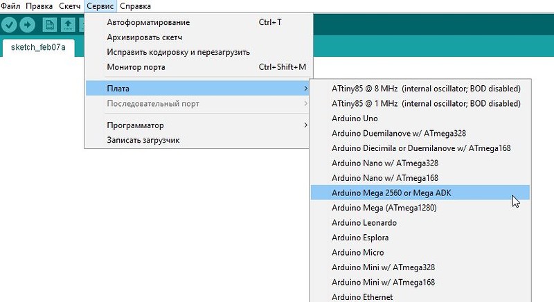
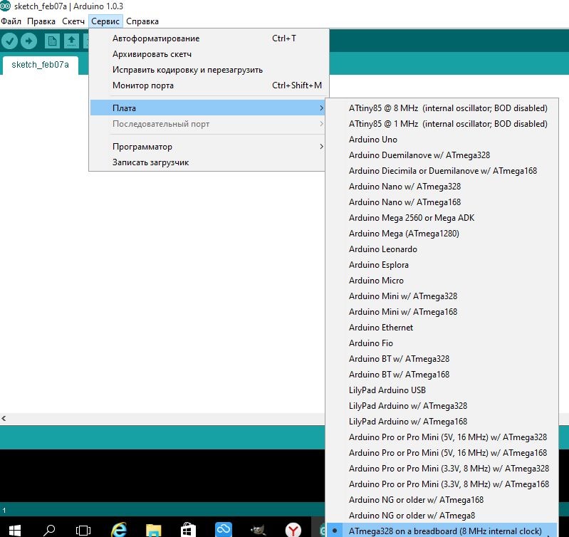
После загрузки скетча программатора необходимо переключиться на целевую плату. Т.е. в нашем случае — ATmega328 с частотой 8 МГц и внутренним задающим генератором. Она будет в списке плат, если описания, о которых говорил выше, скопированы правильно:
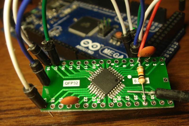
Теперь нужно соединить линии MISO, MOSI и SCK платы-программатора и платы с будущей Arduino, а также подключить RESET, GND и VCC. Плюс питания лучше именно в последнюю очередь.
Исходя из приведенной выше инфографики и описания Arduino Mega, вырисовывается следующая картина:
SPI — Arduino Mega — ATmega328p
MISO — 50 — 16
MOSI — 51 — 15
SCK — 52 — 17
SS (RESET) — 53 — 29
Физическое подключение на ваш вкус, я применил исключительно варварский метод — обычные макетные провода прямо в отверстия платы, без пайки и изоляции:
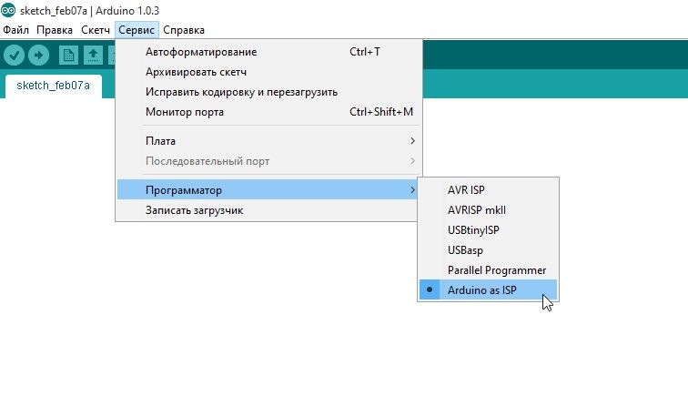
Если все готово — записываем загрузчик. Сначала убеждаемся, что выбран правильный программатор (Сервис — Программатор — Arduino as ISP):
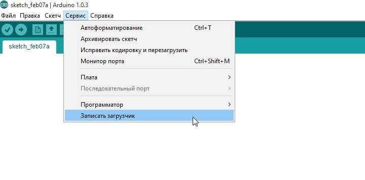
Потом делаем Сервис — Записать загрузчик:
Содержимое архива следует извлечь в папку hardware папки среды Arduino. В дальнейшем я описываю происходящее на примере среды 1.0.3, которой пока пользуюсь.
Когда описания скопированы, следует запустить Arduino и загрузить скетч программатора в Arduino, которая будет использоваться в качестве этого самого программатора. Скетч находится в меню Файл — Примеры — ArduinoISP.
Разумеется, следует выбрать свою плату и порт. Я выбираю Mega, потому что у меня она и есть:
После загрузки скетча программатора необходимо переключиться на целевую плату. Т.е. в нашем случае — ATmega328 с частотой 8 МГц и внутренним задающим генератором. Она будет в списке плат, если описания, о которых говорил выше, скопированы правильно:
Теперь нужно соединить линии MISO, MOSI и SCK платы-программатора и платы с будущей Arduino, а также подключить RESET, GND и VCC. Плюс питания лучше именно в последнюю очередь.
Исходя из приведенной выше инфографики и описания Arduino Mega, вырисовывается следующая картина:
SPI — Arduino Mega — ATmega328p
MISO — 50 — 16
MOSI — 51 — 15
SCK — 52 — 17
SS (RESET) — 53 — 29
Физическое подключение на ваш вкус, я применил исключительно варварский метод — обычные макетные провода прямо в отверстия платы, без пайки и изоляции:
Если все готово — записываем загрузчик. Сначала убеждаемся, что выбран правильный программатор (Сервис — Программатор — Arduino as ISP):
Потом делаем Сервис — Записать загрузчик:
After that, the output is a minimalist Arduino board, to load the skits into which you can use a USB-Serial adapter or a full-fledged Arduino board with such an adapter on board. In the first case, you need to cross-connect the RX and TX, and do not forget to connect the common ground. In the second case, it is additionally necessary to close the RESET Arduino, which is used as an adapter, to earth.
If you, like me, do not have an automatic controller reset circuit before loading the sketch, then there are two options: either pull its reset or just turn on its power when the Arduino environment writes about the start of the load.
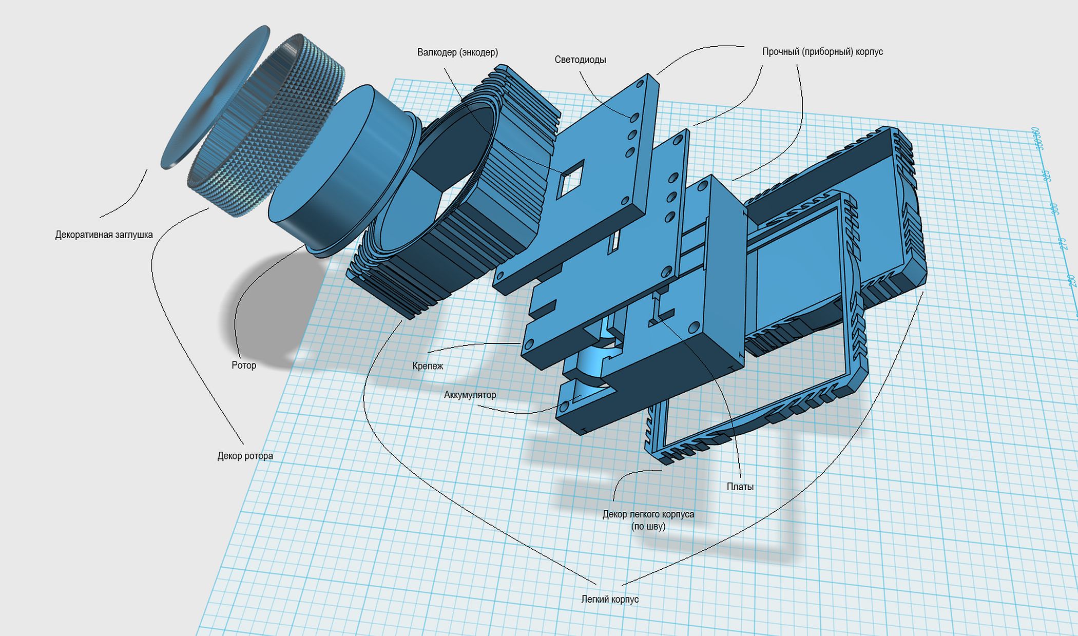
Housing
The case, as I said, is modular. This means that the plastic can be thrown onto the inner part hidden from the eyes, which is stale and no longer suitable. You can wear electronics in it:
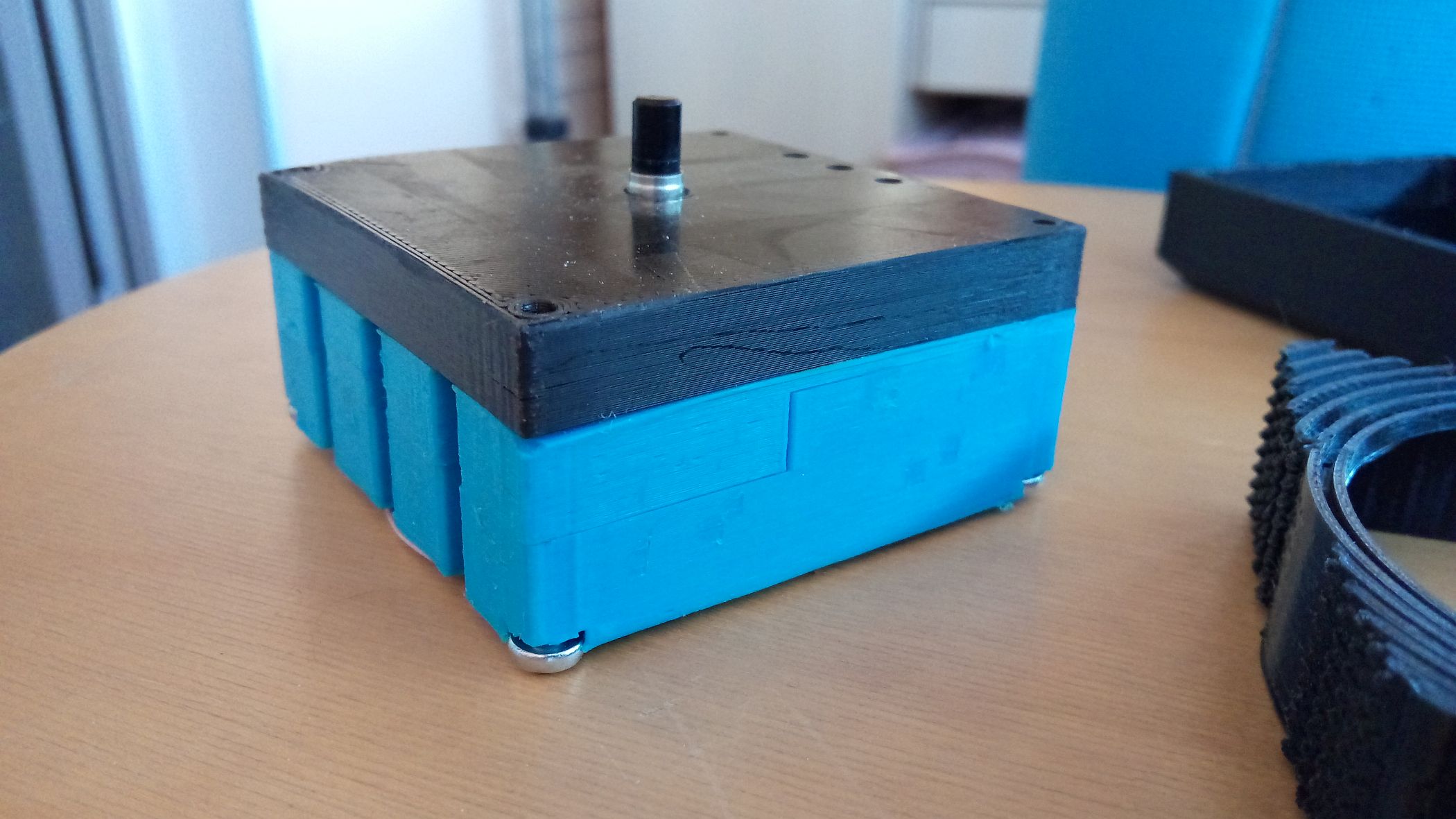
I draw attention to the fact that the body is specific and designed to fit my version of the filling.
I propose to make the rotor transparent so that it disperses the light of the indicators. For greater weighty inside the rotor, you can attach the nut M16: You
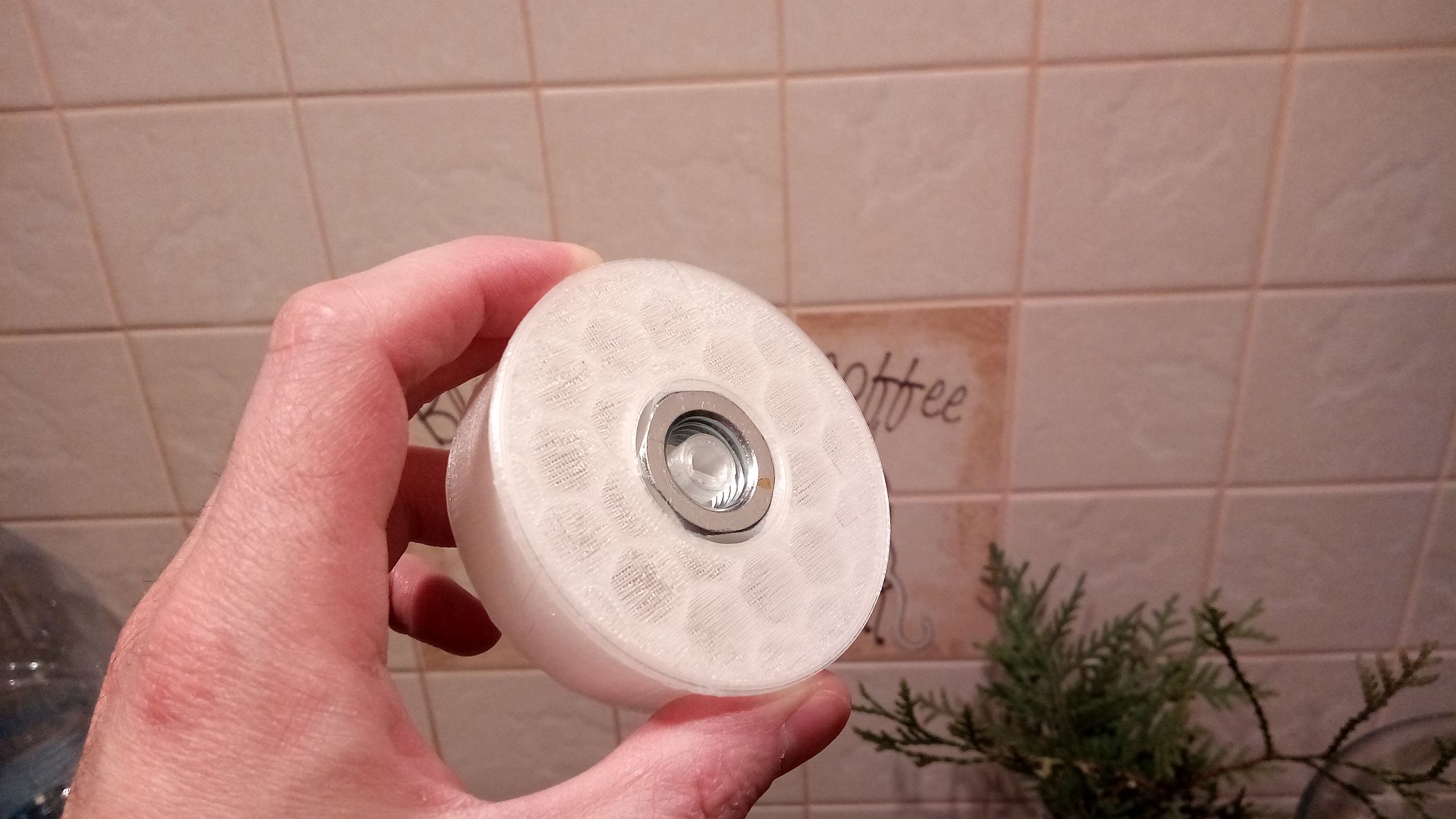
still need the rotor shirt and the cover to it. The lid is simply inserted inside and held on to friction. And, of course, can not do without the top and bottom of the outer case.
I printed the rotor with a filling of 10%, the remaining elements - with a filling of 5%. Plastic - PLA. The set temperature of the nozzle on my printer is 200C on the first three layers, 185C on the following ones. Unfortunately, I can not say what the true temperature of the nozzle. The table is cold.
The assembly is simple.
Boards are placed in the slots of the robust case, LEDs - with legs into the slots of the bottom of the robust case. The transmitter antenna is displayed down, and the wireless charging receiver is also output down — so that it is closer to that charge.
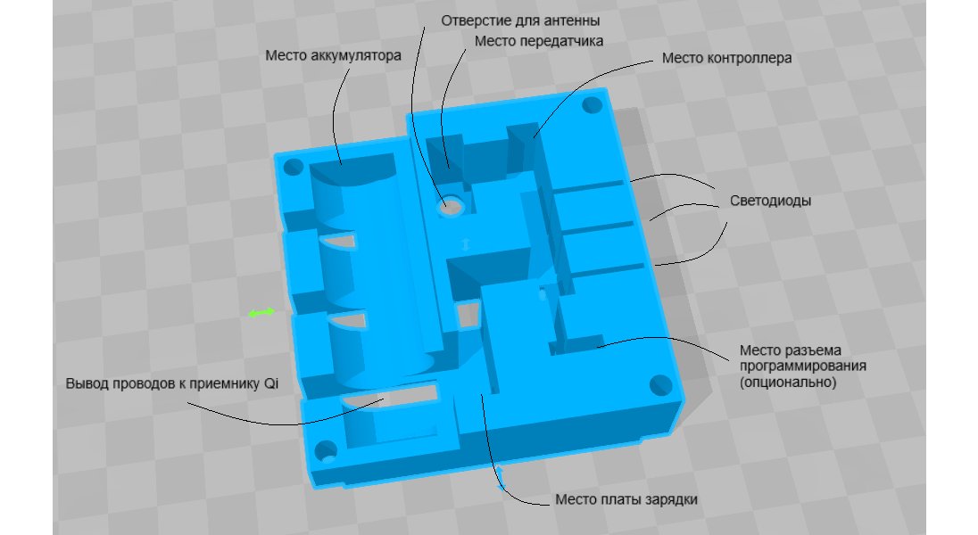
The filling is fixed by an intermediate plate, in the groove of which the encoder wire harness passes.
The encoder is fixed with the upper plate, all together it is tightened with M4x30 screws, which themselves cut threads in plastic.
Now the rugged case can be enclosed in halves of the outer case. A rotor is put on the encoder shaft, and a shirt is attached to the rotor. Optionally, a non-slip mat is glued to the bottom of the case. Another option is a decorative insert that hides the seam between the body halves.
Code
В коде нужно задать команды на включение и выключение своих периферийных устройств. Опционально — поменять таймаут автовыключения.
Это все располагается в секции переменных.
Это все располагается в секции переменных.
// Код сна: http://donalmorrissey.blogspot.ru/2010/04/sleeping-arduino-part-5-wake-up-via.html// Библиотека Livolo: http://forum.arduino.cc/index.php?action=dlattach;topic=153525.0;attach=108106#include<avr/sleep.h>#include<avr/power.h>#include<livolo.h>#define adc_disable() (ADCSRA &= ~(1<<ADEN)) // disable ADC (before power-off) #define adc_enable() (ADCSRA |= (1<<ADEN)) // re-enable ADC#define  txPin  7 //  пин передатчикаLivolo livolo(txPin);
#define PULSESHORT 450  #define PULSELONG  1350#define PULSESYNC  13950#define encA 5#define encB 6 // пины энкодера#define buttonPin 2 // пин кнопки (прерывание)#define roomLed 10 // пин индикатора комнаты#define kitchenLed 9 // пин индикатора кухни#define switchLed 3 // пин индикатора переключения освещения#define switchLedTimeOut 150 // время свечения индикатора переключения освещения#define switchTreshold 4 // количество срабатываний энкодера до переключения#define offDelay 15000 // таймаут автовыключения#define rLev 3 // количество уровней света комнаты#define kLev 3 // количество уровней света кухни#define glev 2 // количество уровней света всего#define txPowerPin 8 // пин питания передатчика#define kitchenBackLightOn1 12#define kitchenBackLightOn2 34#define kitchenMainLightOn 56#define roomBackLightOn 12#define roomMainLightOn1 34#define roomMainLightOn2 56#define mainLightOn 12#define kitchenBackLightOff1 12#define kitchenBackLightOff2 34#define kitchenMainLightOff 56#define roomBackLightOff 12#define roomMainLighOtff1 34#define roomMainLightOff2 56#define mainLightOff 12#define LivoloID 8500volatile byte rotorMode = 0; // режим работы
byte currentMode = 0; // текущий режим работыint curEncA, prevEncA, curButton, prevButton; // текущее значение энкодера, предыдущее
byte encCountPlus = 0; // счетчик энкодера
byte encCountMinus = 0; // счетчик энкодераunsignedlong offTimeOut = 0; // счетчик таймера автовыключенияunsignedlong modeTimeOut = 0; // счетчик таймера короткого нажатия для переключения режимаunsignedlong switchLedTime = 0; // счетчик выключения индикатора переключения освещенияunsignedlong modeTime = 0; // длительность нажатияunsignedint modeTreshold = 500; // пороговая длительность короткого нажатия (короче ххх мс)unsignedint bounceTreshold = 200; // пороговая длительность дребезга контактов
byte rLevState = 0;
byte kLevState = 0;
byte gLevState = 0;
// флаги света k - кухня, r - комната, h - коридор, b - ванная
boolean kBackState = false;
boolean kBackState1 = false;
boolean kMainState = false;
boolean rBackState = false;
boolean rMainState = false;
boolean rMainState1 = false;
boolean hMainState = false;
boolean bMainState = false;
boolean afterSleep = false; // флаг выхода из режима сна
boolean modeTimeOutStart = false;
boolean switchLedOn = false;
boolean allOn = false; // флаг "все включено" для индикатора переключения
boolean allOff = false; // флаг "все выключено" для индикатора переключенияstaticvoidookPulse(int on, int off){
  digitalWrite(txPin, HIGH);
  delayMicroseconds(on);
  digitalWrite(txPin, LOW);
  delayMicroseconds(off);
}
staticvoidrcSend(long remoteCode){
 for (byte reSend = 0; reSend < 8; reSend++) {
  for(byte repeat=0; repeat<4; repeat++){
   for (byte i = 24; i>0; i--) { // transmit remoteID
    byte txPulse=bitRead(remoteCode, i-1); // read bits from remote ID// Serial.print(txPulse);switch (txPulse) {
        case0:  // 00
          ookPulse(PULSESHORT,PULSELONG);
          //ookPulse(PULSESHORT,PULSELONG);break;
        case1:  // 11
          ookPulse(PULSELONG,PULSESHORT);
          //ookPulse(PULSELONG,PULSESHORT);break;
      } // switch
    } // for loop
    ookPulse(PULSESHORT,PULSESYNC); // S(ync)//  Serial.println();
  } // repeat
 }
delay(150);
}
voidswitchLedToggle(){
  digitalWrite(switchLed, HIGH);
  switchLedTime = millis();
  switchLedOn = true;
}
voidlightsUp(boolean lightsUpMode){
// чтобы при включении после сна при "выключении" свет выключался с максимума// а при "включении" - с минимумаif (afterSleep == true) {
    if (lightsUpMode == false) {
      gLevState = 1;
      rLevState = 3;
      kLevState = 3;
    } else
           {gLevState = 0;
            rLevState = 0;
            kLevState = 0;
           }
  afterSleep = false; // сброс признака "после сна"
  }
// Все освещениеif (rotorMode == 2) {
   if (lightsUpMode == false){
    if (allOff == false) {
     switchLedToggle();
     if (digitalRead(buttonPin) == HIGH) {
      // выключить все
      gLevState = 0;
      rLevState = 0;
      kLevState = 0;
      rcSend(kitchenBackLightOff1);
      rcSend(kitchenBackLightOff2);
      rcSend(roomBackLightOff);
      livolo.sendButton(LivoloID, mainLightOff);
    }
   allOff = true;
   allOn = false;
   }
  }
    if (lightsUpMode == true){
      // включить все, что не включеноif (allOn == false) {
     switchLedToggle();
     if (digitalRead(buttonPin) == HIGH) {
      gLevState = 1;
      rLevState = 3;
      kLevState = 3;
      rcSend(kitchenBackLightOn1);
      rcSend(kitchenBackLightOn2);
      rcSend(roomBackLightOn);
      livolo.sendButton(LivoloID, mainLightOff);      // сначала выключим все Livolo
      livolo.sendButton(LivoloID, kitchenMainLightOn); //#1 теперь включим
      livolo.sendButton(LivoloID, roomMainLightOn1);  // #2
      livolo.sendButton(LivoloID, roomMainLightOn2); // #3
      livolo.sendButton(LivoloID, mainLightOn); // #6
      }
      allOn = true;
      allOff = false;
     }
    }
   }
// Кухняif (rotorMode == 1) {
    if (lightsUpMode == false && kLevState > 0) {
      switchLedToggle();
     if (digitalRead(buttonPin) == HIGH) {
      if (kLevState == 3) {
        // выкл верх
       livolo.sendButton(LivoloID, kitchenMainLightOff); // #3
      }
      if (kLevState == 2) {
        // выкл фон 2
      livolo.sendButton(LivoloID, kitchenBackLightOff2); // #6
      }
      if (kLevState == 1) {
        // выкл фон 1
      rcSend(kitchenBackLightOff1);
      }
     }
      if (kLevState!=0) {
      kLevState--;}
       //   Serial.println(kLevState);
   }
    if (lightsUpMode == true && kLevState < 3) {
      switchLedToggle();
      kLevState++;
      if (digitalRead(buttonPin) == HIGH) {
      if (kLevState > 3) {kLevState = 3;}
       //  Serial.println(kLevState);if (kLevState == 1) {
        // вкл фон 1
      rcSend(kitchenBackLightOn1);
      }
      if (kLevState == 2) {
        // вкл фон 2
      livolo.sendButton(LivoloID, kitchenBackLightOn2); // #6
      }
      if (kLevState == 3) {
        // вкл верх
      livolo.sendButton(LivoloID, kitchenMainLightOn); // #3
      }
     }
    }
  }
// Комнатаif (rotorMode == 0) {
   if (lightsUpMode == false && rLevState > 0) {
    switchLedToggle();
    if (digitalRead(buttonPin) == HIGH) {
      if (rLevState == 3) {
        // выкл верх1
      livolo.sendButton(LivoloID, roomMainLighOtff1); //#1
      }
      if (rLevState == 2) {
        // выкл верх
      livolo.sendButton(LivoloID, roomMainLightOff2);  // #2
      }
      if (rLevState == 1) {
        // выкл фон
      rcSend(roomBackLightOff);
      }
    }
      if (rLevState != 0) {
      rLevState--;
      }
    }
    if (lightsUpMode == true && rLevState < 3) {
     switchLedToggle();
     rLevState++;
     if (digitalRead(buttonPin) == HIGH) {
      if (rLevState == 1) {
        // вкл фон
      rcSend(roomBackLightOn);
      }
      if (rLevState == 2) {
        // вкл верх
      livolo.sendButton(LivoloID, roomMainLightOn1); //#1
      }
      if (rLevState == 3) {
        // вкл верх 1
      livolo.sendButton(LivoloID, roomMainLightOn2);  // #2
      }
     }
    }
  }
}
voidwakeUp(){
  detachInterrupt(0);
}
voidsetMode(){
  if (rotorMode >= 2 ) {
     rotorMode = 0;
  } else {
    rotorMode++;
  }
 offTimeOut = millis();
}
voidledBlink(){
  for (byte iLed = 0; iLed<3; iLed++) {
    digitalWrite(kitchenLed, HIGH);
    digitalWrite(roomLed, HIGH);
    delay(100);
    digitalWrite(kitchenLed, LOW);
    digitalWrite(roomLed, LOW);
    delay(100);
 }
}
voidsetLed(){
   if (rotorMode == 0) { // Комната
    digitalWrite(roomLed, HIGH);
    digitalWrite(kitchenLed, LOW);
  }
  if (rotorMode == 1) { // Кухня
    digitalWrite(roomLed, LOW);
    digitalWrite(kitchenLed, HIGH);
  }
  if (rotorMode == 2) { // Комната и кухня
    digitalWrite(roomLed, HIGH);
    digitalWrite(kitchenLed, HIGH);
  }
}
voidenterSleep(){
// ledBlink();
 afterSleep = true;
 digitalWrite(txPin, LOW);
 digitalWrite(txPowerPin, LOW);
 digitalWrite(roomLed, LOW);
 digitalWrite(kitchenLed, LOW);
 digitalWrite(switchLed, LOW);
 pinMode(txPin, INPUT);
 pinMode(txPowerPin, INPUT);
 pinMode(roomLed, INPUT);
 pinMode(kitchenLed, INPUT);
 pinMode(switchLed, INPUT);
 attachInterrupt(0, wakeUp, LOW);
  adc_disable();
  set_sleep_mode(SLEEP_MODE_PWR_DOWN);
  sleep_enable();
  sleep_mode();
 sleep_disable();
 power_all_enable();
 pinMode(txPin, OUTPUT);
 pinMode(txPowerPin, OUTPUT);
 pinMode(roomLed, OUTPUT);
 pinMode(kitchenLed, OUTPUT);
 pinMode(switchLed, OUTPUT);
 digitalWrite(txPin, LOW);
 digitalWrite(txPowerPin, HIGH);
// ledBlink();
 setLed();
 offTimeOut = millis();
 allOn = false;
 allOff = false;
}
voidsetup(){
 // Serial.begin(115200);
 pinMode(txPin, OUTPUT);
 pinMode(txPowerPin, OUTPUT);
 pinMode(roomLed, OUTPUT);
 pinMode(kitchenLed, OUTPUT);
 pinMode(switchLed, OUTPUT);
 digitalWrite(txPin, LOW);
 digitalWrite(txPowerPin, HIGH);
 digitalWrite(roomLed, LOW);
 digitalWrite(kitchenLed, LOW);
 digitalWrite(switchLed, LOW);
//  pinMode(buttonPin, INPUT_PULLUP);
 pinMode(buttonPin, INPUT);
 pinMode(encA, INPUT);
 pinMode(encB, INPUT);
 prevEncA = digitalRead(encA);
 offTimeOut = millis();
 rotorMode = 0;
 setLed();
 prevButton = digitalRead(buttonPin);
}
voidloop(){
if ((millis() - offTimeOut) > offDelay) {
     enterSleep();
 } else {
 // выключение индикации переключения режимов  if (switchLedOn == true) {
   if ((millis() - switchLedTime) > switchLedTimeOut) {
     digitalWrite(switchLed, LOW);
     switchLedOn = false;
   }
 }
// сброс таймера автовыключения при нажатом энкодереif (digitalRead(buttonPin) == LOW) {
  offTimeOut = millis();
}
// переключение режимов
curButton = digitalRead(buttonPin);
  if ((prevButton == HIGH) && (curButton == LOW)) {
    if (modeTimeOutStart == false) {
      modeTimeOut = millis();
      modeTimeOutStart = true;
    }
  } else {
        if (modeTimeOutStart == true) {
          modeTime = millis() - modeTimeOut;
          if ((modeTime < modeTreshold) && (modeTime > bounceTreshold)) {
            setMode();
            modeTimeOutStart = false;
            prevButton = digitalRead(buttonPin);
          } else {
              modeTimeOutStart = false;
              prevButton = digitalRead(buttonPin);
          }
        }
  }
// переключение индикации режимов if (currentMode != rotorMode) { // если текущий режим не совпадает с установленным, то устанавливаем текущий режим
  currentMode = rotorMode;
// и включаем соответствующую индикацию
  setLed();
}
// подсчет импульсов
 curEncA = digitalRead(encA);
   if ((prevEncA == LOW) && (curEncA == HIGH)) {
     offTimeOut = millis();
     if (digitalRead(encB) == LOW) {
       encCountMinus++;
       encCountPlus = 0;
      // Serial.println("Encoder Minus");if (encCountMinus > switchTreshold) {
          encCountMinus = 0;
          lightsUp(false);
        }
     } else {
       encCountPlus++;
       encCountMinus = 0;
      // Serial.println("Encoder Plus");       if (encCountPlus > switchTreshold) {
          encCountPlus = 0;
          lightsUp(true);
        }
     }
   }
   prevEncA = curEncA;
 }
}
Model housing by reference .
Everything.
PS: I tried not to forget anything, but I could. If so, I apologize and I will do my best to answer the leading questions correctly and correct mistakes.