USB bootloader for AVR microcontrollers
The article describes how to quickly start the USB bootloader for the ATmega32 microcontroller using the Objective Development usbasploader bootloader as an example .
USB bootloader technology provides one single possibility - no need for a special programmer to replace the software ( firmware ) in the device - just connect to a computer via USB. There is no longer any need to carry a programmer with you, since a computer and USB are everywhere. If your breadboard is equipped with a bootloader, then you can save money on buying a programmer or time on its manufacture - this is important for beginners.
A lot of bootloaders have been made for AVR - see [ 1]. For the article, I chose usbasploader [ 2 ] because it is compatible with the very popular USBasp programmer . This allows you to upgrade the firmware for both Linux and Windows using popular programs (see [3]) avrdude, eXtreme Burner - AVR, Khazama AVR Programmer, and even from the BASCOM-AVR programming environment (BASCOM-AVR programming system - a small miracle worthy of a separate article). In addition, usbasploader comes with all the sources, is well-documented and easily adapted to the needs of the user (more on that later).
The usbasploader bootloader works very simply - when connected to USB, it pretends to be a USBasp programmer. Therefore, all programs that support it will overwrite the firmware in your device, as if they were using the USBasp programmer. The bootloader is located in the high addresses of the flash memory of the microcontroller's programs, and writes the user program to the lower addresses (usually starting at address 0), i.e., when the microcontroller is flashed, the bootloader is not overwritten. After the recording finishes, bootloader transfers control to the user program. Now more about how it works with ATmega microcontrollers, using the example of ATmega32 .
For ATmega32, the usbasploader is compiled so that it is placed in flash from the address 7000h (I recall that the memory address of ATmega32 programs is 0000h..7FFFh, and the command address is a multiple of two bytes, that is, the command addresses are in the range 0000h..37FFh) . For the user program, free space 0000h..6FFFh (28672 bytes) remains. The usbasploader loader uses the ATmega32 microcontroller embedded in the ability to start from the address located in the higher addresses of the program memory (several fixed addresses are available, selected by jumpers - fuses, see [ 4 ]). In order to always transfer control to the 0x7000 address upon power-up and reset, you must program the jumpers (fuse, fuse-bits) BOOTSZ0 and BOOTSZ1to the appropriate state (4000h bytes or 2048 words of program code should be allocated for the bootloader), as well as programming the BOOTRST jumper . After this, the code, when reset or turned on, will start not from address 0, but from address 3800h in the words of the AVR commands, or from address 7000h in flash bytes (I recall that the minimum size of the AVR command is two bytes).
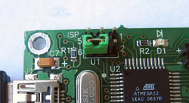
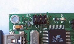
Having received control after a reset, the usbasploader code checks the condition of its activation, i.e., the signal by which it should start working as a USBasp programmer. Usually such a signal is the closure of a leg to the ground. For the breadboard I chose PB5 as such a legmicrocontroller ATmega32. This leg is also a MOSI signal output to the connector, so it is very convenient to send a log signal to PB5 from the jumper between pins 4 and 6 of the U1 ISP connector. 0. So, the usbasploader code checks the level on port PB5, and if there is a log. 0 (the jumper between legs 4 and 6 of the U1 ISP connector is installed), then work starts as a USBasp programmer. That is, with the jumper installed, the bootloader is activated when the power is turned on, and if it is connected to the computer, the USBasp USB device will appear in the computer. If there is no jumper at the time of power-up (at the same time, log 1 is read on PB5 by the microcontroller), then usbasploader immediately transfers control to the user program (to address 0). Here is a simple launch algorithm.
In usbasploader it is possible to change the behavior of the bootloader, for this it is enough to edit three functions (they are very simple, and are located in the bootloaderconfig.h file) - bootLoaderInit , bootLoaderCondition , bootLoaderExit . Assignment of functions is almost obvious by name. The bootLoaderInit function is intended to configure an environment in which it is possible to track the activation condition of the bootloader:
The code is very simple - it only connects the pull-up internal pull-up resistor to the PB5 foot - this allows you to determine the presence of a jumper between pins 4 and 6 of the U1 ISP connector, and lights up the red LED on the breadboard. The bootLoaderCondition function is designed to check whether or not there is a jumper between pins 4 and 6: If the jumper is on, the PB5 leg is read as a log. 0, and the bootLoaderCondition function will return 1 (which means bootloader is working). If there is no jumper, the function will return 0, which means inactivity for the bootloader (control is immediately transferred to address 0 - to the user program). The bootLoaderExit function does nothing for me, it only extinguishes the red layout LED:
The above code for the bootLoaderInit, bootLoaderCondition, bootLoaderExit functions can be considered as an example - they can and should be altered to fit your needs, and then usbasploader will work just the way you want. In conclusion, I will describe the process in steps on the Windows platform (it is assumed that you already have AVRStudio and WinAVR installed. If not, read the instructions on how to install them using the link [ 6 ]).
[ How to embed usbasploader in your project ]
1 . You need to download the latest version of usbasploader (see [ 2 ]), for example, USBaspLoader.2009-03-20.zip . If you have a prototype board AVR-USB-MEGA16, then I suggest downloading the option from the link [ 5] - everything is ready there, and steps 2, 3, 4 can be skipped. Unpack to any convenient folder.
2 . Edit the settings in the Makefile. There you need to change:
a) the definition of F_CPU is the frequency in Hz at which the microcontroller operates. The frequencies are 12, 15, 16, 16.5 and 20 MHz.
b) determination of DEVICE for your type of microcontroller.
c) address (hexadecimal format, units in bytes) of the usbasploader BOOTLOADER_ADDRESS code download.
d) (optional, if you will not flash the chip from the Makefile) check and, if necessary, adjust the definitions of FUSEOPT and LOCKOPT, as well as the definition of AVRDUDE.
3 . Edit bootloaderconfig.h. There you need to check and, if necessary, change:
a) macro USB_CFG_IOPORTNAME - the letter of the name of the port to which the USB D- and D + signals are connected.
b) the USB_CFG_DMINUS_BIT and USB_CFG_DPLUS_BIT macros are the port numbers to which the D- and D + signals are connected. The D + signal must be connected to the INT0 interrupt leg.
c) function code bootLoaderInit, bootLoaderExit and macro bootLoaderCondition.
4 . Recompile the project by typing make. On the command line, you will see something like this:

After successful compilation, get the main.bin and main.hex files in the project’s root folder - ready-made firmware for usbasploader. By the way, in the hexfiles folder there are already several compiled versions of firmware for crystals ATmega8, ATmega88, ATmega168, for different frequencies of quartz.
5. It is necessary using the programmer to flash the usbasploader code into the chip, to correctly install the fuse. The meaning of this operation is to put the usbasploader code in the upper memory area (at the address BOOTLOADER_ADDRESS), and set the fuses in such a way that the bootloader code starts to be executed when the power is reset or turned on (I already wrote about this). For details on fuses, see the link [ 4 ] and in the datasheet for your microcontroller. For an ATmega32 microcontroller, for example, the fuses should be set as follows:
LOW FUSE BYTE : 0x CF
HIGH FUSE BYTE : 0x D8 (you can also 0x98 to enable JTAG debugging)
LOCKOPT BYTE : 0x EF
The AVR-USB-MEGA16 development board can be purchased with usbasploader and fuses already flashed, so steps 1, 2, 3, 4, 5 do not need to be done.
6 . You must connect the firmware breadboard to the computer via USB. If they didn’t mess up anything, then the layout will be defined in the system as a new device and the Windows system will ask for a driver. The driver can be downloaded from the page [ 2 ], or taken from the archive by the link [ 5 ]. For Linux, a driver is not needed.
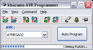
7 . We need one of the programs that work with the USBasp programmer (see links [3]). For Linux users, avrdude is suitable, but for Windows users, the choice is very wide. I recommend Khazama AVR Programmer with a very simple and convenient interface.


[How to work with the usbasploader bootloader using the example AVR-USB-MEGA16 and Khazama AVR Programmer ]
1 . Place a jumper between the legs 4 and 6 of the U1 ISP connector.
2 . Connect the breadboard to the computer via USB. The red LED on the breadboard will turn on, and the USBasp programmer will be detected on the Windows system.
3 . Launch the Khazama AVR Programmer. In the settings, remove the option to clear the memory of the chip (Command -> Program Options -> uncheck Erase Chip). Select your chip from the drop-down list. Download the firmware hex file (via the menu File -> Load FLASH file to Buffer). Press the large Auto Program button to start programming. The crystal is programmed very quickly, in a few seconds.
After programming is complete, the red LED will turn off and your program will start running from address 0 (which you just wrote down).
4 . Remove the jumper between legs 4 and 6 of the U1 ISP connector.
UPD100711 : wrote an article about another USB bootloader - BootloadHID . The source code and style of work is very similar to USBASPloader. It differs in that it requires a special program on the computer, but it is easier to integrate into younger chips (starting with ATmega8), since the requirements for the size of the bootloader section are reduced.
[ Links ]
1 . Bootloader for AVR microcontrollers .
2 . Usbasploader homepage.
3 . Programs for working with the USBasp programmer are AVRDUDE , BASCOM-AVR , Khazama AVR Programmer , eXtreme Burner-AVR .
4 . Engbedded Atmel AVR® Fuse Calculator - jumper calculator for AVR.
5 . My version of usbasploader, sharpened for the AVR-USB-MEGA16 breadboard with the ATmega32 microcontroller (project for AVRStudio with source and compiled options for quartz 12 MHz, 16 MHz).
6 . USB device development - how to get started with AVR USB (V-USB) and libusb libraries .
7 . USBasp bootloader with XOR encryption.
USB bootloader technology provides one single possibility - no need for a special programmer to replace the software ( firmware ) in the device - just connect to a computer via USB. There is no longer any need to carry a programmer with you, since a computer and USB are everywhere. If your breadboard is equipped with a bootloader, then you can save money on buying a programmer or time on its manufacture - this is important for beginners.
A lot of bootloaders have been made for AVR - see [ 1]. For the article, I chose usbasploader [ 2 ] because it is compatible with the very popular USBasp programmer . This allows you to upgrade the firmware for both Linux and Windows using popular programs (see [3]) avrdude, eXtreme Burner - AVR, Khazama AVR Programmer, and even from the BASCOM-AVR programming environment (BASCOM-AVR programming system - a small miracle worthy of a separate article). In addition, usbasploader comes with all the sources, is well-documented and easily adapted to the needs of the user (more on that later).
The usbasploader bootloader works very simply - when connected to USB, it pretends to be a USBasp programmer. Therefore, all programs that support it will overwrite the firmware in your device, as if they were using the USBasp programmer. The bootloader is located in the high addresses of the flash memory of the microcontroller's programs, and writes the user program to the lower addresses (usually starting at address 0), i.e., when the microcontroller is flashed, the bootloader is not overwritten. After the recording finishes, bootloader transfers control to the user program. Now more about how it works with ATmega microcontrollers, using the example of ATmega32 .
For ATmega32, the usbasploader is compiled so that it is placed in flash from the address 7000h (I recall that the memory address of ATmega32 programs is 0000h..7FFFh, and the command address is a multiple of two bytes, that is, the command addresses are in the range 0000h..37FFh) . For the user program, free space 0000h..6FFFh (28672 bytes) remains. The usbasploader loader uses the ATmega32 microcontroller embedded in the ability to start from the address located in the higher addresses of the program memory (several fixed addresses are available, selected by jumpers - fuses, see [ 4 ]). In order to always transfer control to the 0x7000 address upon power-up and reset, you must program the jumpers (fuse, fuse-bits) BOOTSZ0 and BOOTSZ1to the appropriate state (4000h bytes or 2048 words of program code should be allocated for the bootloader), as well as programming the BOOTRST jumper . After this, the code, when reset or turned on, will start not from address 0, but from address 3800h in the words of the AVR commands, or from address 7000h in flash bytes (I recall that the minimum size of the AVR command is two bytes).
Having received control after a reset, the usbasploader code checks the condition of its activation, i.e., the signal by which it should start working as a USBasp programmer. Usually such a signal is the closure of a leg to the ground. For the breadboard I chose PB5 as such a legmicrocontroller ATmega32. This leg is also a MOSI signal output to the connector, so it is very convenient to send a log signal to PB5 from the jumper between pins 4 and 6 of the U1 ISP connector. 0. So, the usbasploader code checks the level on port PB5, and if there is a log. 0 (the jumper between legs 4 and 6 of the U1 ISP connector is installed), then work starts as a USBasp programmer. That is, with the jumper installed, the bootloader is activated when the power is turned on, and if it is connected to the computer, the USBasp USB device will appear in the computer. If there is no jumper at the time of power-up (at the same time, log 1 is read on PB5 by the microcontroller), then usbasploader immediately transfers control to the user program (to address 0). Here is a simple launch algorithm.
In usbasploader it is possible to change the behavior of the bootloader, for this it is enough to edit three functions (they are very simple, and are located in the bootloaderconfig.h file) - bootLoaderInit , bootLoaderCondition , bootLoaderExit . Assignment of functions is almost obvious by name. The bootLoaderInit function is intended to configure an environment in which it is possible to track the activation condition of the bootloader:
static inline void bootLoaderInit(void)
{
    DDRB |= (1 << PB0);  //выход для красного светодиода
    //на PB5 (MOSI, контакт 4 коннектора U1 ISP) подключаем pull-up и зажигаем светодиод
    PORTB |= (1 << PB5)|(1 << PB0);
}
The code is very simple - it only connects the pull-up internal pull-up resistor to the PB5 foot - this allows you to determine the presence of a jumper between pins 4 and 6 of the U1 ISP connector, and lights up the red LED on the breadboard. The bootLoaderCondition function is designed to check whether or not there is a jumper between pins 4 and 6: If the jumper is on, the PB5 leg is read as a log. 0, and the bootLoaderCondition function will return 1 (which means bootloader is working). If there is no jumper, the function will return 0, which means inactivity for the bootloader (control is immediately transferred to address 0 - to the user program). The bootLoaderExit function does nothing for me, it only extinguishes the red layout LED:
static inline uint8_t bootLoaderCondition()
{
    if (!(PINB & (1 << PB5)))
    {
        return 1;
    }
    else
    {
        // no boot loader
        return 0;
    }
}
static inline void bootLoaderExit(void)
{
    PORTB &= ~(1 << PB0);  //гасим светодиод
}
The above code for the bootLoaderInit, bootLoaderCondition, bootLoaderExit functions can be considered as an example - they can and should be altered to fit your needs, and then usbasploader will work just the way you want. In conclusion, I will describe the process in steps on the Windows platform (it is assumed that you already have AVRStudio and WinAVR installed. If not, read the instructions on how to install them using the link [ 6 ]).
[ How to embed usbasploader in your project ]
1 . You need to download the latest version of usbasploader (see [ 2 ]), for example, USBaspLoader.2009-03-20.zip . If you have a prototype board AVR-USB-MEGA16, then I suggest downloading the option from the link [ 5] - everything is ready there, and steps 2, 3, 4 can be skipped. Unpack to any convenient folder.
2 . Edit the settings in the Makefile. There you need to change:
a) the definition of F_CPU is the frequency in Hz at which the microcontroller operates. The frequencies are 12, 15, 16, 16.5 and 20 MHz.
b) determination of DEVICE for your type of microcontroller.
c) address (hexadecimal format, units in bytes) of the usbasploader BOOTLOADER_ADDRESS code download.
d) (optional, if you will not flash the chip from the Makefile) check and, if necessary, adjust the definitions of FUSEOPT and LOCKOPT, as well as the definition of AVRDUDE.
3 . Edit bootloaderconfig.h. There you need to check and, if necessary, change:
a) macro USB_CFG_IOPORTNAME - the letter of the name of the port to which the USB D- and D + signals are connected.
b) the USB_CFG_DMINUS_BIT and USB_CFG_DPLUS_BIT macros are the port numbers to which the D- and D + signals are connected. The D + signal must be connected to the INT0 interrupt leg.
c) function code bootLoaderInit, bootLoaderExit and macro bootLoaderCondition.
4 . Recompile the project by typing make. On the command line, you will see something like this:
After successful compilation, get the main.bin and main.hex files in the project’s root folder - ready-made firmware for usbasploader. By the way, in the hexfiles folder there are already several compiled versions of firmware for crystals ATmega8, ATmega88, ATmega168, for different frequencies of quartz.
5. It is necessary using the programmer to flash the usbasploader code into the chip, to correctly install the fuse. The meaning of this operation is to put the usbasploader code in the upper memory area (at the address BOOTLOADER_ADDRESS), and set the fuses in such a way that the bootloader code starts to be executed when the power is reset or turned on (I already wrote about this). For details on fuses, see the link [ 4 ] and in the datasheet for your microcontroller. For an ATmega32 microcontroller, for example, the fuses should be set as follows:
LOW FUSE BYTE : 0x CF
HIGH FUSE BYTE : 0x D8 (you can also 0x98 to enable JTAG debugging)
LOCKOPT BYTE : 0x EF
The AVR-USB-MEGA16 development board can be purchased with usbasploader and fuses already flashed, so steps 1, 2, 3, 4, 5 do not need to be done.
6 . You must connect the firmware breadboard to the computer via USB. If they didn’t mess up anything, then the layout will be defined in the system as a new device and the Windows system will ask for a driver. The driver can be downloaded from the page [ 2 ], or taken from the archive by the link [ 5 ]. For Linux, a driver is not needed.
7 . We need one of the programs that work with the USBasp programmer (see links [3]). For Linux users, avrdude is suitable, but for Windows users, the choice is very wide. I recommend Khazama AVR Programmer with a very simple and convenient interface.
[How to work with the usbasploader bootloader using the example AVR-USB-MEGA16 and Khazama AVR Programmer ]
1 . Place a jumper between the legs 4 and 6 of the U1 ISP connector.
2 . Connect the breadboard to the computer via USB. The red LED on the breadboard will turn on, and the USBasp programmer will be detected on the Windows system.
3 . Launch the Khazama AVR Programmer. In the settings, remove the option to clear the memory of the chip (Command -> Program Options -> uncheck Erase Chip). Select your chip from the drop-down list. Download the firmware hex file (via the menu File -> Load FLASH file to Buffer). Press the large Auto Program button to start programming. The crystal is programmed very quickly, in a few seconds.
After programming is complete, the red LED will turn off and your program will start running from address 0 (which you just wrote down).
4 . Remove the jumper between legs 4 and 6 of the U1 ISP connector.
UPD100711 : wrote an article about another USB bootloader - BootloadHID . The source code and style of work is very similar to USBASPloader. It differs in that it requires a special program on the computer, but it is easier to integrate into younger chips (starting with ATmega8), since the requirements for the size of the bootloader section are reduced.
[ Links ]
1 . Bootloader for AVR microcontrollers .
2 . Usbasploader homepage.
3 . Programs for working with the USBasp programmer are AVRDUDE , BASCOM-AVR , Khazama AVR Programmer , eXtreme Burner-AVR .
4 . Engbedded Atmel AVR® Fuse Calculator - jumper calculator for AVR.
5 . My version of usbasploader, sharpened for the AVR-USB-MEGA16 breadboard with the ATmega32 microcontroller (project for AVRStudio with source and compiled options for quartz 12 MHz, 16 MHz).
6 . USB device development - how to get started with AVR USB (V-USB) and libusb libraries .
7 . USBasp bootloader with XOR encryption.