Asynchronous Programming - Graph Editor
 Sometimes in the process of describing business logic, it is necessary to create a graph of asynchronous operations with internal dependencies, i.e. when tasks are performed asynchronously, but some tasks depend on others and are thus forced to “wait” until it can be started. In this post I want to show how this problem can be solved by creating a graphical DSL that will allow the developer to visually define the dependency graph.
 Nb: article in English and source code are here
Introduction
Generally speaking, domain-specific languages (domain-specific languages, DSL for short) come in three forms. The first variety is text DSL, which is defined exclusively through text and structure, and is associated with a specific process of converting this text to code. The second variety is structural DSL, where the content is defined using a tree or graph-like editor. I want to discuss the third type - a graphic DSL, where the developer works with a graphic editor to create a visual structure that can later be turned into code.
In this article, we will create a simple graphical DSL that allows the end user to define asynchronous operations that will be organized using the Pulse & Wait mechanism. To compile the attached example, you need Visual Studio 2008 with the Visual Studio SDK. We will use the Microsoft DSL Tools (included with the SDK) to create our DSLs.
Description of the problem
Since it is difficult to work with Pulse & Wait, I want to create a graphic DSL that would allow me to determine the sequence of operations that can be organized using the Pulse & Wait mechanism. In particular, I want to be able to drag and drop asynchronous blocks in the editor, as well as the ability to define relationships between them to form rules for asynchronous, dependent execution.
DSL creation
Before we begin, let me outline the most important points when working with DSL Tools:
- In DSL Tools, graphic DSLs themselves are made using graphic DSL. This may seem confusing at first glance, but in principle, you should understand that most of our asynchronous DSLs (which I call AsyncDsl here) will be developed using visual elements - not with a programming language. Of course, there will be a lot of code behind the scenes, but we will not encounter it often.
- DSL tools make extensive use of T4 technology. Our graphical DSL is really just a visual representation of XML, and T4 turns this XML into code. That way, when you edit visual elements with DSL Tools, you are actually editing XML.
- Your DSL is still created using C # and it compiles. You can extend it with partial classes, etc., which will allow your DSL to behave in a certain way. We will not do anything like this in this article.
- Creating DSL with DSL Tools only applies to the visual part - the part that allows the user to visually create XML models. The part that turns it into plain text code is a separate issue that we will meet later.
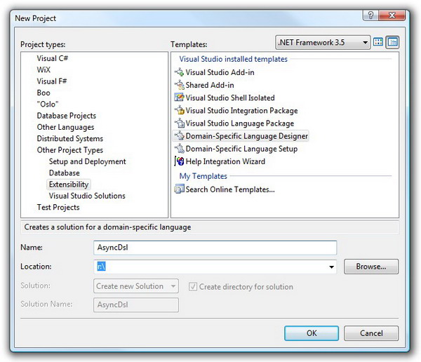
To create a DSL project in Visual Studio, select New Project, and then Other Project Types → Extensibility → Domain-Specific Language Designer.
After clicking OK, you will be shown a wizard where you can identify some of the features of the DSL that you create.
- On the first page, in addition to defining the name of your language, you can also select the initial template. This template determines what initial features DSL has - for example, by choosing Task Flow, you determine that the initial DSL elements will belong to flowchart-like structures. Regardless of which template you choose at this stage, you can always override the behavior of your DSL by deleting the initially generated elements.
- The second page allows you to select the file extension (extension) for your DSL. This extension will appear in the places where you will embed your DSL in your own projects. In addition to the extension, the wizard generates an icon.
- The third page allows you to specify some lines that define your DSL, such as the name of the product to which your DSL belongs.
- The fourth page actually forces you to sign your assembly - either with an existing one or with a new key.
When you finish working with the wizard, you will get a DSL definition framework. If you have never worked with DSL-functionality in Visual Studio, then the screenshot may shock you a little.
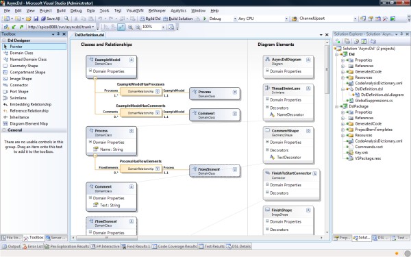
The following elements are involved in the DSL editing process:
- Dsl Designer Toolbox. This panel contains all the elements that you will work with when designing your DSL. These elements are used in the same way as for example in WinForms - take an element and drag it into the editor window (that is the central window with strange boxes).
- The DSL designer himself. Actually, this is a file with the extension
.dsl, but as you can see, the editor is megavisual - as I said, DSLs and by themselves are built using other DSLs. This DSL has two parts - on the left side there are classes and relations between them, and on the right side there are visual elements, i.e. visual reflections of DSL concepts that the end user will work with. Thus, one can imagine DSL as follows: on the right is visualization, on the left is logic. - Solution Explorer. When you create a DSL, you will get two projects - one that defines the DSL that you make, and another that defines the editor of the DSL related components. We will talk about this later - now it’s important to mark only one single button that transforms all templates:
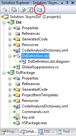
This is a very important button. As I said before, DSLs are XML specifications that transform into code. This means that in order to update the definition of our DSL (and the definition is also DSL), you need to transform all the templates in C #. The button above does just that. Therefore, if you suddenly do not reflect any changes in the final DSL that you are sure you made, then you forgot to click on this button. - The DSL explorer. This is a brand new panel in the studio that presents your DSL in the form of a tree and looks something like this:

This tree encapsulates many of the structural aspects of DSL. It is important to note that some nodes of the tree have their own set of properties, which can be seen by pressing F4. - Pages for editing property pages exist both for elements of the DSL Explorer tree and for visual elements in the DSL editor. Some DSL elements can be edited directly "in the editor" - for example, you can define the form of relations (one-to-many, many-to-many, etc.) between two elements without opening the property panel. How it is more convenient to do is up to you.
Let's now delve into the process of creating our DSL.
Arranging visual elements
As I already wrote, the toolbox contains all the elements that you have to work with. These elements are divided into two groups - “logical” and “visual”. Logic elements are those that define the structure (i.e. domain) in your DSL. Visual elements reflect those rectangles, lines, and loose elements that the user operates when working with DSL.
The central concept of the logical structure of the DSL - a domain class (domain class). This class can represent anything you want , depending on which subject area you are working with. Since we work with asynchronous operations, one of our domain classes will be called
Operation: 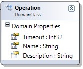
A domain class may have properties, i.e. values that the user can set. Our class
Operationhas properties Timeout, Nameand Descriptionthat the end user will be able to determine when, how to drag an instance of the object Operationto his model. There is a small problem - in fact, the user does not drag the domain class directly into his model. Instead, he drags himself into a model
OperationShape, which is a visual reflection Operation. This class is formed from GeometryShape(taken from the same toolbox): 
Defining the domain class
Operationas well as its visual representationOperationShape, they need to be tied together (if you run it as is, nothing will work). To do this, use the Diagram Element Map element. In fact, this thing is a line that connects two elements, defining an association between them. But even if you add it, still nothing will work.Relations between elements
Before we start working on creating toolbox controls for our DSL (which is fun), we need to talk about relationships between elements. There are two types of relationships - Embedding Relationship and Reference Relationship. If you use embedding relationship, element A will be completely enclosed in element B. For example, if I have a swimlane (a large horizontal piece of visual space) and I need to insert whole classes into it, then it makes sense to use embedding relationship. If I just have blocks to which you need to attach comments, a reference relationship will go.
Let's look at how we will use the elements for our specific task. In the “root” of our mozhele we have an element
ExampleModel. I won’t even change the name of this element, because he will not appear in the final DSL. In order to determine that my model contains processes and comments, I draw the lines of the embedding relationship between the respective classes and get the following picture: 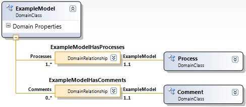
Orange boxes symbolize the relationship, with the names and cardinality of the relationship on both sides. Cardinality is later regulated by the DSL designer, so that the end user will not be able to violate it. As for relations, the meaning of these orange boxes is that they allow you to bind different domain classes together when editing an already finished DSL.
Attention:DSL designer applies a number of rules to your language, one of which requires that all elements are part of something. This means that all elements must be reduced to one, "container" container. (If you recall that DSL == XML, the reason for this requirement should be obvious.)
We used the embedding relationship to tell our DSL that both processes and comments are part of the overall model. Now we can use the reference relationship to determine that processes can have comments, and that the two elements can be linked.
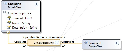
The dashed line above means a reference relationship, i.e. in our case, the operation may just referon a comment - not contain it. Of course, this relationship has its own visual element (a line that connects the operation and the comment), which we will talk about now.
Toolboxes finally
Having received the logical and visual part of your DSL, you need to give users the ability to drag items from this DSL to their designer. Here's where to start - from the Editor node in DSL Explorer:

To create a new element for a toolbox, right-click on the entire DSL. You will see the following menu:
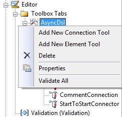
There are two options - connectors and elements. Connectors are lines (even possibly with arrows) that connect elements together. And elements are block-shaped structures.
After creating a new element, press F4 and you will see the properties of this element:
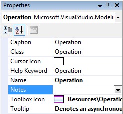
What is important here is that several of these properties must be filled in - otherwise DSL will not start. Of those that obviously need to be defined - the definition of a domain class that reflects the element, as well as the definition of an icon. (A couple of default icons are already provided, so if you are too lazy to create your own, you can use the ready-made ones.)
Launch!
We summarize the process of creating a DSL:
- Made a basic DSL using a wizard
- Added domain classes representing the concepts we need, such as a process .
- We added the relationship between the domain names - in our case, we determined the fact that the operations belong to the general model, and that they have comments. Also added transition operations between operations, as well as elements of the beginning and end.
- We identified the visual elements that our DSL will use.
- Associated visual elements with domain classes.
- We created toolbox controls and associated them with the corresponding classes.
Our DSL is half ready: we have defined only the visual part. After we have transformed all the templates and launched our language, we can finally start playing with our DSL:
Of the concept
For our asynchronous DSL, we have identified the following idioms:
- Operation
This is our unit of work, for example 'make tea'. We mean that the operation can go without any failures. - Process A
process is a sequence of operations in a graph. The only reason we added this element is to be able to keep multiple operation graphs in the same class. - Start and Finish
The process must start and end somewhere, so we created two elements to mark the start and end states. - Finish-to-start transition
This transition determines that an operation can only be started after another operation has completed. - Start-to-start transition
This transition determines that an operation can only begin when another operation has been started, and not earlier.
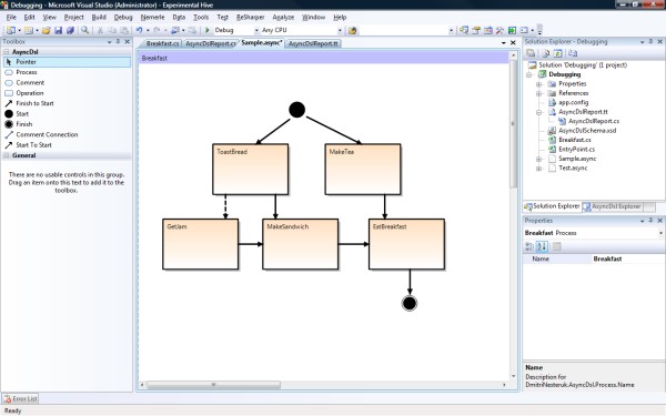
Let's look at a real-life example: eating breakfast (I know, not very smart). To make breakfast, you need to put a kettle, and also put bread in a toaster - in any order. While everything is preparing, I want to get jam, but only if I already turned on the toaster. When I got the finished bread and got the jam, I can make a sandwich. And only when both a sandwich and tea are ready, can I start eating breakfast.
Using our DSL, the whole process can be defined like this:

As you might have guessed, bold lines symbolize finish-to-start, and dashed lines symbolize start-to-start.
Transform the model using T4
The visual breakfast model exists only as a DSL, so we need T4 to turn it into a full-fledged code. Fortunately, by the time we need to do the conversion, the model has already been converted to the XML format, and we can only bypass it and generate what we need.
The production of the final result in T4 moves by several methods, such as
WriteLine()(writes a line to the final file) and Push/PopIndent()(hold the number of indents on the stack). I will not be presenting the T4 transformation code here - it can be downloaded from the link above. Instead, I will show what our DSL will produce from the definition of breakfast.
namespace Debugging


{


  using System.Threading;


  partial class Breakfast


  {


    private readonly object MakeSandwichLock = new object();


    private readonly object EatBreakfastLock = new object();


    private readonly object GetJamLock = new object();


    private bool MakeTeaIsDone;


    private bool ToastBreadIsDone;


    private bool GetJamIsDone;


    private bool MakeSandwichIsDone;


    private bool MakeTeaStarted;


    private bool ToastBreadStarted;


    private bool GetJamStarted;


    private bool MakeSandwichStarted;


    protected internal void MakeTea()


    {


      MakeTeaImpl();


      lock(EatBreakfastLock)


      {


        MakeTeaIsDone = true;


        Monitor.PulseAll(EatBreakfastLock);


      }


    }


    protected internal void ToastBread()


    {


      lock(GetJamLock)


      {


        ToastBreadIsDone = true;


        Monitor.PulseAll(GetJamLock);


      }


      ToastBreadImpl();


      lock(MakeSandwichLock)


      {


        ToastBreadIsDone = true;


        Monitor.PulseAll(MakeSandwichLock);


      }


    }


    protected internal void GetJam()


    {


      lock(GetJamLock)


        if(!(ToastBreadStarted))


          Monitor.Wait(GetJamLock);


      GetJamImpl();


      lock(MakeSandwichLock)


      {


        GetJamIsDone = true;


        Monitor.PulseAll(MakeSandwichLock);


      }


    }


    protected internal void MakeSandwich()


    {


      lock(MakeSandwichLock)


        if(!(ToastBreadIsDone && GetJamIsDone))


          Monitor.Wait(MakeSandwichLock);


      MakeSandwichImpl();


      lock(EatBreakfastLock)


      {


        MakeSandwichIsDone = true;


        Monitor.PulseAll(EatBreakfastLock);


      }


    }


    protected internal void EatBreakfast()


    {


      lock(EatBreakfastLock)


        if(!(MakeTeaIsDone && MakeSandwichIsDone))


          Monitor.Wait(EatBreakfastLock);


      EatBreakfastImpl();


    }


  }


}
A lot of code! But then this code reflects the structure that we have defined. Now all that remains is to use the generated structure:
namespace Debugging


{


  partial class Breakfast


  {


    AutoResetEvent eatHandle = new AutoResetEvent(false);


    Random rand = new Random();


    public void Prepare()


    {


      ThreadStart[] ops = new ThreadStart[] {


        MakeTea,


        GetJam,


        ToastBread,


        MakeSandwich,


        EatBreakfast };


      foreach (ThreadStart op in ops)


        op.BeginInvoke(null, null);


      eatHandle.WaitOne();


    }


    private int RandomInterval


    {


      get


      {


        return (1 + rand.Next() % 10) * 100;


      }


    }


    public void MakeTeaImpl()


    {


      Thread.Sleep(RandomInterval);


      Console.WriteLine("Make tea");


    }


    public void ToastBreadImpl()


    {


      Thread.Sleep(RandomInterval);


      Console.WriteLine("Toast bread");


    }


    public void GetJamImpl()


    {


      Thread.Sleep(RandomInterval);


      Console.WriteLine("Get jam");


    }


    public void MakeSandwichImpl()


    {


      Thread.Sleep(RandomInterval);


      Console.WriteLine("Make sandwich");


    }


    public void EatBreakfastImpl()


    {


      Thread.Sleep(RandomInterval);


      Console.WriteLine("Eat breakfast");


      eatHandle.Set();


    }


  }


}
The result of calling this code is something like this:
Make tea
Toast bread
Get jam
Make sandwich
Eat breakfast
All done
Although the course
Make teaand Toast breadmay appear in a different order.Conclusion
DSL Tools is a sophisticated yet powerful toolkit. A key characteristic of this package is the ease of working with the language after it has been defined. Here I could only superficially describe the work with DSL Tools, as opportunities and nuances are many. I hope that this post motivates someone to conduct their own research. ■