See the invisible: look inside the thermal imager Seek Thermal (and not just)
Good day,%% username! Today I will tell (and show a little) what you can (but not always have to) do with a Seek Thermal thermal imager.

Blue electrical tape, where are the maker without her?
Recently, there have been a lot of articles on Giktatimes about this thermal imaging camera. You can read, for example, here , here and here , even with the connection to the STM-32 , but today we are not talking about this - there will not be a boring theory and pictures of cats, only the flesh. Under the cut, there is a story about how to make the iOS version of Seek Thermal version for Android and Raspberry Pi, why you need it and what else you can learn in the process of digging in the insides of the thermal imager. Interested please.
It all started with my passion for airsoft. Yes, yes, I did not play enough at war in childhood, so I consider it quite important for me to go on a weekend to shoot 6-mm plastic balls in my own kind. And since adults are around the uncle and everything is serious too, the night phase happens in airsoft games. And there comes a time when an enemy begins to fathom under each bush and tree, and NVDs and thermal imagers take over the role of the kings of the battlefield. More precisely, their owners. I also wanted to count myself, but, of course, the toad prevented me.
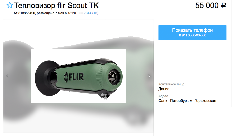
But here you are. The entry threshold for thermal imagers is about 50 cubic meters.
After reviewing the proposals, I became disheartened, mixed with despair. For fifty thousand, we have a basic version of the device with a filling in the form of a 160x120 matrix (thanks, even though the screen was set to VGA) and the screen refresh rate is <9 Hz. But Google was a help, and soon the eevblog.com site, which was already mentioned on this resource more than once, appeared to me with a detailed 100 page story about an interesting device, combining a 208x156 dot matrix, fully accessible for use, and very good hacking. that moment, the happy owners have already managed to wrap up some relatively simple applications on Python and C ++ to get a picture of the very microbolometric matrix that distinguishes the device from its own kind with good resolution for sane money. And yes,
But the natural question arose: what, in fact, to do with it further? The idea of running with the phone through the fields and forests at night was not too tempting, so it was decided to create a thermal imager from scratch, with blackjack and ... well, you understand. This is a separate story, and I will tell it in a dedicated article, or even a few - with code and glands - but for now, having arrived home and stuck a freshly- purchased device into the Odroid C1 + single-board device with a nastyly Android, I soon became completely upset .
The device worked poorly. First of all, there were spots on the picture, which I first associated with the contamination of the lens - as it turned out later, the matrix itself was dirty and the number of dead pixels was also not pleasing. Secondly, in five minutes the matrix started to make a lot of noise, the quality of the picture fell and it was simply impossible to use the camera as originally planned.
Conclusion: when purchasing Seek Thermal, let the camera work for 5-10 minutes to evaluate its function after warming up.

The noise is similar to my case. From the corner of the image there is a gradient caused by the incorrect operation of the shutter (shutter).
At that time, I did not have a complete understanding of how to deal with the problems that had arisen, and I decided to fight as best I could. To check whether the device works or not, it was decided to find another one. It may seem wasteful and illogical - but I assumed this: if the problem is in the software (and as it turned out, it was partially in the software - since I ran everything on the crookedly assembled Odroid / Android, which did not support the update of the official application) - then I will have two thermal imagers . Well, if not - then at least one.
Time passed, the proposals of used imagers appeared and disappeared, and then one day - lo and behold! - I came across a camera in the version for the iPhone. Well, okay, I thought - the adapter and all issues are resolved!

Four-legged friend - filmed in the apple application
And here it is not. How many I did not beat the tambourine, to make the camera work through the lightning-microusb adapter (and after all, it was still a task to find it, so that both USB and lightning mom, power, and data ...) failed. There was only one way out - to climb inside. And I got.
The video is not mine - I used it as a disassembly tool, and for general development in the field of thermal imagers in general, and Seek Thermal in particular:
Good thing there are people like Mike. In the second part,
disassembling the Seek Thermal camera to the printed circuit board - do not look at sensitive geeks ... To disassemble the Seek Thermal camera, you need:
- Seek Thermal camera
- something flat and hard to open the case - a spatula, for example - 2-3 pieces. different
- multimeter - 1 pc.
- an oscilloscope or a logic analyzer - optional
- straight arms - 1 pair
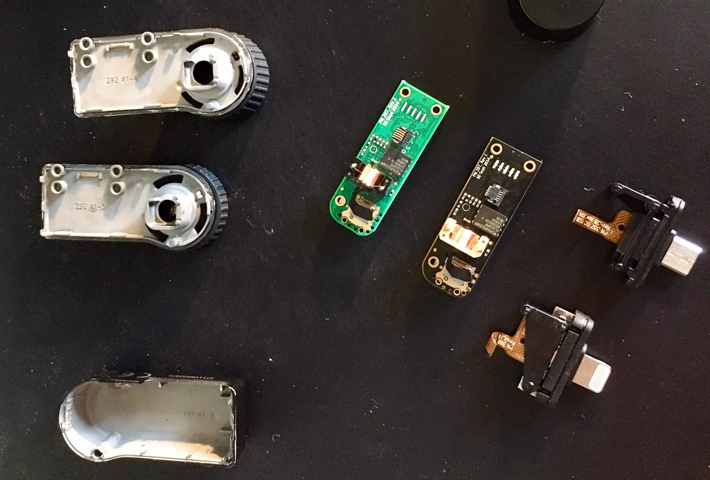
Having a video disassembly on hand, you can try to gently open the halves of the magnesium alloy, not much of his parsings. Guess what color is the board for iOS device? :)
I started the autopsy from the edge far from the lens. There is no latch inside, only a few drops of glue. Further, I was faced with the task of correctly interpreting the wiring of connectors inside the iOS and Android versions of the camera, and to connect to the corresponding pins on the board.
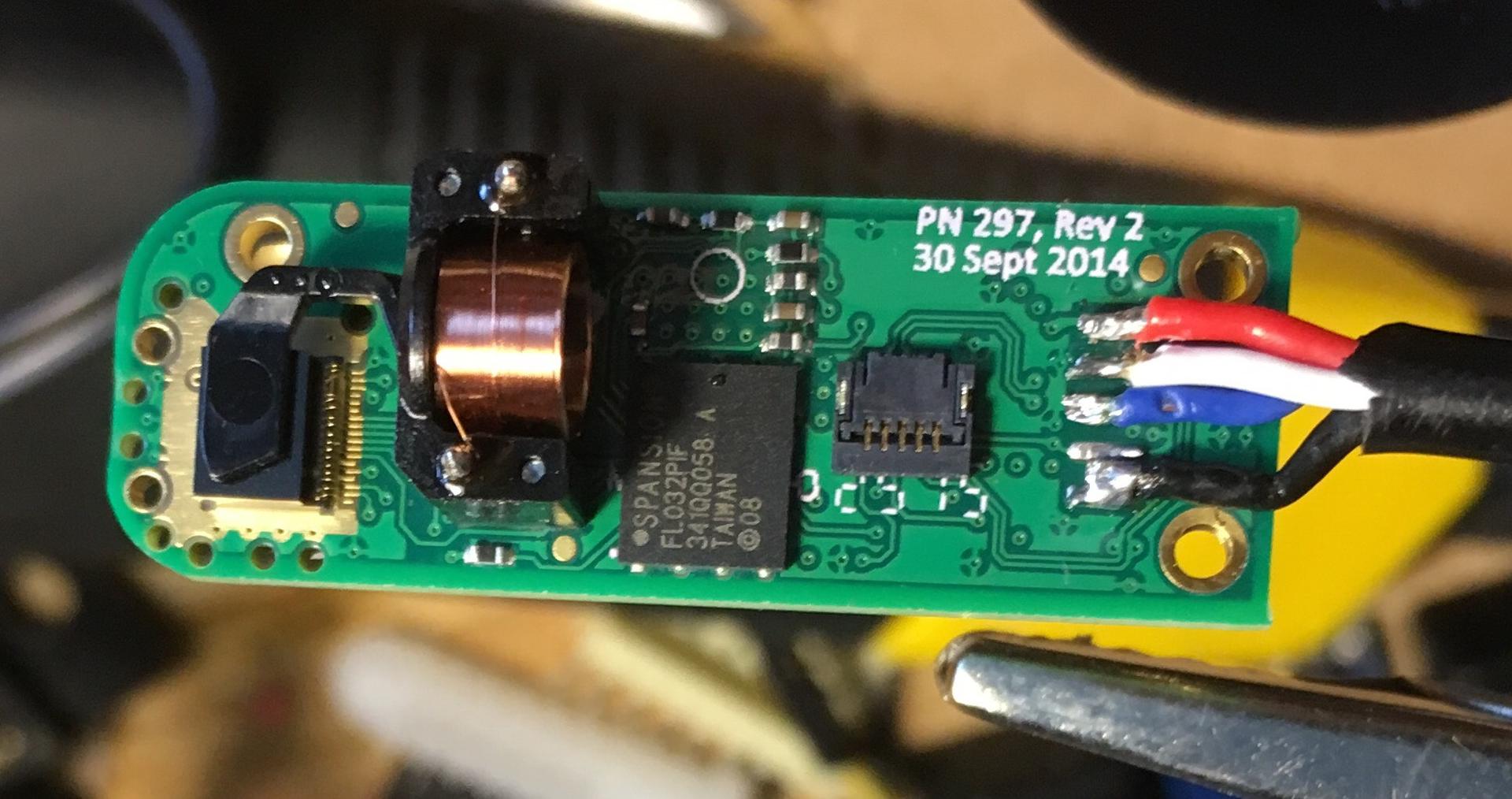
I was afraid that I would have to intercept the camera signal at a deep level - because manufacturers could easily cram into the interface responsible for connecting to apple products, and even the data processing function. But in the video disassembly it is mentioned that the only difference between the apple and non-apple version of the camera is the identification chip. This meant that the contacts / soldering points on the board and the wiring of the cables would most likely coincide physically and functionally. The point in question was put by the same version of the board (rev 2 from 09/30/2014) on both devices.
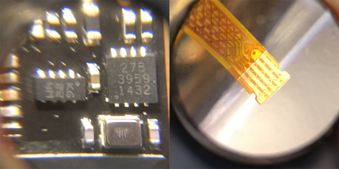
The same chip (square on the right). The sametea train
Without thinking twice, I swapped the trains of iOS and Android versions, and with a sinking heart, I started the data processing program from the camera (by the time it was already written on Python for Raspberry Pi based on the code of Comrade Cynfab from here ).

Hooray! Earned!
A fresh thermal imager wound up immediately, showing a better picture quality. Well, we postpone it for the finished project, and we will deal with the “old” device.

The device without an identification chip was not expected to start when connected to an iPhone - although it was determined.
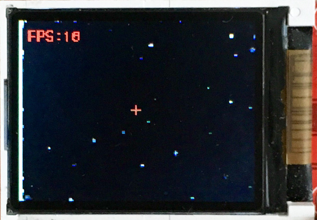
By the way, the operation of the thermal imager from the inside looks like this:
In normal mode, the shutter works every 1-8 seconds to calibrate the matrix.
The matrix of the Android version of the camera was very dusty. I blew it with compressed air - subjectively, the image quality slightly (but not categorically) improved.
However, when reading a picture from a matrix, there is a certain amount of “broken whips”.
On “raw” frames from the camera, a well-known among those who like to dig deeper than Seek Thermal users is a “patent grid” - a hexagonal pattern of non-working points. According to some users of eevblog, these are intentionally disabled (missing?) Pixels of the matrix - every 15th is done in order to avoid possible patent disputes with FLIR that have a patent for a microbolometric matrix.

Grid of “patent” pixels (picture from eevblog)
Since I do not plan to connect the device to iOS devices, I will not need a cable with a lightning connector. Connection can be made by soldering to very conveniently located terminals on the camera board itself. There is a very good parsing video view of this connection (however, just in case, I also rang contacts with a multimeter).
Connection (top to bottom): USB V +, data -, data +, ground.
UPD
iOS version with microUSB connector, the location of contact pads corresponds to the one indicated on the connector board.
Having soldered to the contacts, I brought out an already complete USB type A tail, which can be conveniently plugged into a computer, including the Raspberry Pi.
What we have in the rest:
See in the following series: how to make friends Seek Thermal with the Raspberry Pi, and the Raspberry Pi with the screen from Nokia; picking in the code of an unofficial application, raw pictures and undocumented features, as well as assembling this all into a single functioning prototype.
Well, traditionally for articles about thermal imagers, selfies in the microwave range:
All good.
PS Disclamer: All operations described in the article were made solely for research purposes. The author is not responsible for any damage, direct or indirect, caused due to the lawful (or unlawful) use of the information presented in the materials of the article. Everything that you do, you do at your own peril and risk.
Blue electrical tape, where are the maker without her?
Recently, there have been a lot of articles on Giktatimes about this thermal imaging camera. You can read, for example, here , here and here , even with the connection to the STM-32 , but today we are not talking about this - there will not be a boring theory and pictures of cats, only the flesh. Under the cut, there is a story about how to make the iOS version of Seek Thermal version for Android and Raspberry Pi, why you need it and what else you can learn in the process of digging in the insides of the thermal imager. Interested please.
It all started with my passion for airsoft. Yes, yes, I did not play enough at war in childhood, so I consider it quite important for me to go on a weekend to shoot 6-mm plastic balls in my own kind. And since adults are around the uncle and everything is serious too, the night phase happens in airsoft games. And there comes a time when an enemy begins to fathom under each bush and tree, and NVDs and thermal imagers take over the role of the kings of the battlefield. More precisely, their owners. I also wanted to count myself, but, of course, the toad prevented me.
But here you are. The entry threshold for thermal imagers is about 50 cubic meters.
After reviewing the proposals, I became disheartened, mixed with despair. For fifty thousand, we have a basic version of the device with a filling in the form of a 160x120 matrix (thanks, even though the screen was set to VGA) and the screen refresh rate is <9 Hz. But Google was a help, and soon the eevblog.com site, which was already mentioned on this resource more than once, appeared to me with a detailed 100 page story about an interesting device, combining a 208x156 dot matrix, fully accessible for use, and very good hacking. that moment, the happy owners have already managed to wrap up some relatively simple applications on Python and C ++ to get a picture of the very microbolometric matrix that distinguishes the device from its own kind with good resolution for sane money. And yes,
But the natural question arose: what, in fact, to do with it further? The idea of running with the phone through the fields and forests at night was not too tempting, so it was decided to create a thermal imager from scratch, with blackjack and ... well, you understand. This is a separate story, and I will tell it in a dedicated article, or even a few - with code and glands - but for now, having arrived home and stuck a freshly- purchased device into the Odroid C1 + single-board device with a nastyly Android, I soon became completely upset .
The device worked poorly. First of all, there were spots on the picture, which I first associated with the contamination of the lens - as it turned out later, the matrix itself was dirty and the number of dead pixels was also not pleasing. Secondly, in five minutes the matrix started to make a lot of noise, the quality of the picture fell and it was simply impossible to use the camera as originally planned.
Conclusion: when purchasing Seek Thermal, let the camera work for 5-10 minutes to evaluate its function after warming up.
The noise is similar to my case. From the corner of the image there is a gradient caused by the incorrect operation of the shutter (shutter).
At that time, I did not have a complete understanding of how to deal with the problems that had arisen, and I decided to fight as best I could. To check whether the device works or not, it was decided to find another one. It may seem wasteful and illogical - but I assumed this: if the problem is in the software (and as it turned out, it was partially in the software - since I ran everything on the crookedly assembled Odroid / Android, which did not support the update of the official application) - then I will have two thermal imagers . Well, if not - then at least one.
Time passed, the proposals of used imagers appeared and disappeared, and then one day - lo and behold! - I came across a camera in the version for the iPhone. Well, okay, I thought - the adapter and all issues are resolved!
Four-legged friend - filmed in the apple application
And here it is not. How many I did not beat the tambourine, to make the camera work through the lightning-microusb adapter (and after all, it was still a task to find it, so that both USB and lightning mom, power, and data ...) failed. There was only one way out - to climb inside. And I got.
The video is not mine - I used it as a disassembly tool, and for general development in the field of thermal imagers in general, and Seek Thermal in particular:
Good thing there are people like Mike. In the second part,
disassembling the Seek Thermal camera to the printed circuit board - do not look at sensitive geeks ... To disassemble the Seek Thermal camera, you need:
- Seek Thermal camera
- something flat and hard to open the case - a spatula, for example - 2-3 pieces. different
- multimeter - 1 pc.
- an oscilloscope or a logic analyzer - optional
- straight arms - 1 pair
Having a video disassembly on hand, you can try to gently open the halves of the magnesium alloy, not much of his parsings. Guess what color is the board for iOS device? :)
I started the autopsy from the edge far from the lens. There is no latch inside, only a few drops of glue. Further, I was faced with the task of correctly interpreting the wiring of connectors inside the iOS and Android versions of the camera, and to connect to the corresponding pins on the board.
I was afraid that I would have to intercept the camera signal at a deep level - because manufacturers could easily cram into the interface responsible for connecting to apple products, and even the data processing function. But in the video disassembly it is mentioned that the only difference between the apple and non-apple version of the camera is the identification chip. This meant that the contacts / soldering points on the board and the wiring of the cables would most likely coincide physically and functionally. The point in question was put by the same version of the board (rev 2 from 09/30/2014) on both devices.
The same chip (square on the right). The same
Without thinking twice, I swapped the trains of iOS and Android versions, and with a sinking heart, I started the data processing program from the camera (by the time it was already written on Python for Raspberry Pi based on the code of Comrade Cynfab from here ).
Hooray! Earned!
A fresh thermal imager wound up immediately, showing a better picture quality. Well, we postpone it for the finished project, and we will deal with the “old” device.
The device without an identification chip was not expected to start when connected to an iPhone - although it was determined.
By the way, the operation of the thermal imager from the inside looks like this:
In normal mode, the shutter works every 1-8 seconds to calibrate the matrix.
The matrix of the Android version of the camera was very dusty. I blew it with compressed air - subjectively, the image quality slightly (but not categorically) improved.
However, when reading a picture from a matrix, there is a certain amount of “broken whips”.
On “raw” frames from the camera, a well-known among those who like to dig deeper than Seek Thermal users is a “patent grid” - a hexagonal pattern of non-working points. According to some users of eevblog, these are intentionally disabled (missing?) Pixels of the matrix - every 15th is done in order to avoid possible patent disputes with FLIR that have a patent for a microbolometric matrix.
Grid of “patent” pixels (picture from eevblog)
Since I do not plan to connect the device to iOS devices, I will not need a cable with a lightning connector. Connection can be made by soldering to very conveniently located terminals on the camera board itself. There is a very good parsing video view of this connection (however, just in case, I also rang contacts with a multimeter).
Connection (top to bottom): USB V +, data -, data +, ground.
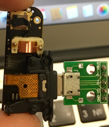
UPD
iOS version with microUSB connector, the location of contact pads corresponds to the one indicated on the connector board.
Having soldered to the contacts, I brought out an already complete USB type A tail, which can be conveniently plugged into a computer, including the Raspberry Pi.
What we have in the rest:
- two live thermal imagers with USB connectivity
- understanding that a native application is much better at handling images than informal ones
- +1 for disassembly-assembly skill of devices without haze
- If you decide to perform a similar operation with your imager, conduct it at your own risk :)
See in the following series: how to make friends Seek Thermal with the Raspberry Pi, and the Raspberry Pi with the screen from Nokia; picking in the code of an unofficial application, raw pictures and undocumented features, as well as assembling this all into a single functioning prototype.
Well, traditionally for articles about thermal imagers, selfies in the microwave range:
All good.
PS Disclamer: All operations described in the article were made solely for research purposes. The author is not responsible for any damage, direct or indirect, caused due to the lawful (or unlawful) use of the information presented in the materials of the article. Everything that you do, you do at your own peril and risk.