Micro-UPS Ionistors
Good day to all respected community. I have the honor to offer the Hubrovites interested in radio electronics a few considerations and a specific implementation of the backup power supply on ionistors (they are supercapacitors with a double electric layer), designed to ensure the correct completion of the processor module on an ARM microcontroller running under standard Linux Debian.
The problem arose in front of your humble servant in the following guise: you need to correctly extinguish the Linux OS (running on the Embedded solution) when the external power is turned off. This power was supplied from a standard USB 2.0 port to a previously made box-device through at least a standard USB-B connector. The inexperienced user of this device preferred to pull out the USB cable corny, following the principle of "UnPlug-NoPlay-NoProblem". It is clear that an embedded solution without hard disks and with virtual memory zeroed during configuration is resistant to such force majeure, but a couple of thousand user-hours of operation have shown that it does not always work “without problems”.
I had to wrinkle my brain and go into a creative trance. Upon leaving the trance, the first possible way to solve the problem materialized - the psychological one, which at first seemed the most attractive. The line of thought was approximately as follows - why does the ordinary user jerk a stick sticking in the USB port with an unshakable hand? Probably because neither he himself nor his closest acquaintances lost in this way their thesis, dissertation or annual report. Why the same user did not pull a printer cable from a working printer in the days of ona? Probably because either he saw, or he heard from someone’s lips, how he had to buy a new MB or Centronics on ISA (PCI). I do not want (from the word in general) that my box was pulled out unceremoniously. What needs to be done for this? Correct, form the required user behavior.
I had to shake the skills of circuitry and tracing, and the next version of the box got an RGB LED and a button on the front panel, as well as a piezo signal with a nasty timbre inside. A simple program determined whether the extreme shutdown passed correctly. If it was incorrect and the user's misconduct was the first on her flash memory, then the control action followed: instead of the indicator pleasing yellow and green, the box blinked with a cutting eye red and vilely squealed a couple of minutes before it calmed down and started to load. Relapse was punishable by five minutes, an even more vile heather and a line in the manual that the box, blocked due to repeated incorrect shutdown, is removed from the warranty, here.
You know, the method turned out to be surprisingly effective. But here the Dear Customer put forward a wish that before disconnecting the box would still inform the server that it was taking time from the scene. Now some, but a source of energy was required. The brain from the next creative trance returned with the thought: a lithium-polymer battery is our everything! Common thinking added a lot of skepticism to this thought: I didn’t really want to charge the battery every time I turned it on, because the number of charge-discharges is a consumed resource, as well as the subject of cynical deception by battery manufacturers of innocent customers. Charge not every time you turn it on, but as it discharges? So it is necessary to fence the whole garden, calibrate the battery, measure the voltage on it with good accuracy. In general, yes and then came the stage Samsung Galaxy with its incendiary batteries. Imagining a fire in the place where the box was supposed to stand, I had to voluntarily wave a saber and stop the painful deliberation of the second idea.
Going into a trance for the third time, a creative genius brought to light ionistors. And what, it seems not bad. The capacity is in farads, the number of charge-discharge cycles is not limited, as it were, the volt is really not enough - 2.7 maximum per cell, and they are not very cascaded. There was already nothing to ponder over the lack of options, and again I had to tackle the circuitry together with the trace.
Searching the Internet's vast expanses brought some catch, and, for a moment of thought, it was decided to stop on the Linear LTC3110 microcircuit. Looking ahead, I’ll say that a couple more options have been tested, but not particularly successfully. If the reader is interested in the details of the choice - you are welcome in PM. Of the available options, the LTC3110 contains almost everything you need to build a backup power source on ionistors:
- it has a step-up converter, which makes the designer not particularly limited in the choice of supply voltage;
- this converter uses inductance for energy storage, which significantly increases the efficiency and makes it possible to give a couple of amperes to the load;
- it is possible to limit the current consumed during charging in the range of 125mA - 2A, which is especially important when powered by USB;
- there is a built-in circuit for individual balancing of series-connected ionistors to increase the stored power and reliability;
- the chip is equipped with leads indicating the degree of charge of the ionistors;
- and, for dessert, there is an additional comparator, the thresholds of which are set by the user.
For details and examples of applications, I send the curious Reader to the datasheet on the microcircuit, the almighty Google with the "LTC3110 pdf" spell to help you.
In theory, to build a workable Micro-UPS, the LTC3110 itself needs to add a circuit that provides power to the box in the normal mode, if there is a connection to a working USB. The IC ST1S10PHR was chosen for this honorable role, whose unpretentious disposition and low price have been known and tested for a long time. I also had to add a key that breaks the power supply circuit of the main consumers during the initial charging of the ionistors. This key allows you to solve two problems: firstly, the initial charging time is reduced (since almost everything consumed by USB goes to the ionistors), and secondly, it eliminates the unpleasant possibility of blackout when the UPS is so undercharged that the energy supply is still not enough for the correct one shutdown. Moreover, A “high start” with fully charged ionistors allows the circuit to sometimes (but not very often) consume more current than the USB port can give - the deficit will be replenished from the ionistors. Such a situation may arise, for example, when recording a large block of information on a capacious USB flash drive that is powered along with the box.
I think that the introductory part can be completed on this and move on to a specific work scheme.
This is how the micro-UPS circuit on the ionistors looks.
Power is supplied from the USB 2.0 port (upper left corner of the circuit). On DA1, according to the recommended scheme, a step-down converter 5V -> 3.3V is assembled from a datasheet. Its only feature is an additional filter from high-frequency ringing on L2 and C7. If desired, these elements can be excluded. Resistors R3 ... R5 are used for emergency discharge of ionistors before transportation, for example, or before setting up the entire board as a whole, otherwise the power source remains on it, and powerful enough to burn anything. The discharge resistors are connected or disconnected by jumper SA1. VT1, C16, R17 and R18 - the key to power the main consumers, it has already been mentioned above and will have to add a few words below. Everything else is the standard LTC3110 harness from the datasheet.
3V3SBY is the standby power of the control circuit, in the box it is implemented on the CPLD EPM240T100 from Altera, but nothing prevents it from being executed on a microcontroller or discrete logic. 3V3 is the main power supply of the box reserved by UPS. Micro-UPS status information is displayed on PWRFAIL, BATFULL and BATLOW with self-explanatory names. PWRFAIL is activated when there is a loss of power from USB, BATFULL indicates that the charge reaches the level of 95% (5.2V), BATLOW shows a decrease in charge level to 40% (2.1V). If desired, this level can be adjusted by selecting R6 and R7, guided by the datasheet. Unfortunately, such a trick does not work with the BATFULL level - it is hammered into the IC with nails.
The micro UPS controls two signals: PWRON and BATOFF. PWRON turns on the main power, BATOFF turns off the UPS as a whole.
The general logic of micro UPS operation is as follows:
If you wish, it is easy to organize any other micro-UPS control logic, for example, by increasing the BATLOW enable level to 60% (selecting R6 and R7), use it as a signal to stop, disconnecting by force from the full discharge C8 and C9.
In the end, quickly go over the configurable parameters of the circuit. R1 and R2 determine the output voltage of DA1, another voltage may require the replacement of C1, C2, C4-C6 and L1. The ratings of C8 and C9 determine only the times of charging and discharging the UPS, I personally tried from 4.7 to 100 Farads, theoretically there are no restrictions. R6 and R7 determine the activation level of BATLOW. The voltage of the maximum charge of the ionistors depends on the ratio R8 / R9. R11 determines the current consumed from 5V USB, at the indicated resistance, the circuit consumes 0.5A. The R12 / R14 ratio sets a drop level of 5V USB, which will be defined as power failure (PWRFAIL). R15 / R16 determines the output voltage of DA2 in discharge mode.
The output signals of the LTC3110 are made according to the "open drain" scheme so as not to be tied to a specific supply voltage. In my circuit, pull-up resistors for them are involved in CPLD, it is not a problem to use them in any modern microcontroller. Well, if you decide to assemble a control circuit on K155, then you have to take care of the resistors yourself.
A few words about the C16. Obtaining this knowledge took me the most time spent on the UPS prototype board. After all, what is the problem? In the datasheet, black in English says that if you want the sum of the current consumed by the main circuit and the charging current of the ionistors to be guaranteed not to exceed the limit set by R11, please kindly power the main circuit from the RSENS output. OK, agreed. And then more interesting. Since your circuit can have anything, up to a short circuit (short circuit, it is a short circuit, it is short), says the datasheet, the LTC3110 is equipped with a special protection circuit. OK, very nice. And now for the fun part. We read the datasheet further: and so that the protection scheme is not mistaken, please, provide the total capacity of the power line NOT MORE, Karl, 10 microFarads. Goofy ... For everything about everything, and do not deny yourself anything. And really any load greater than 10uF when connected wedges ... Do not be deceived, Basurman. I had to make a slight delay in the key on VT1, which gives C16. I understand that for some time VT1 will not be in the key mode, but between heaven and earth (in the sense, between VCC and GND), which is not great at all. But at least it works. Such is the "new hawa." For zealots of the purity of key modes, I’ll add that I tried not to put C16, but an inductance of 1.5 μH in series with VT1 - everything works great.
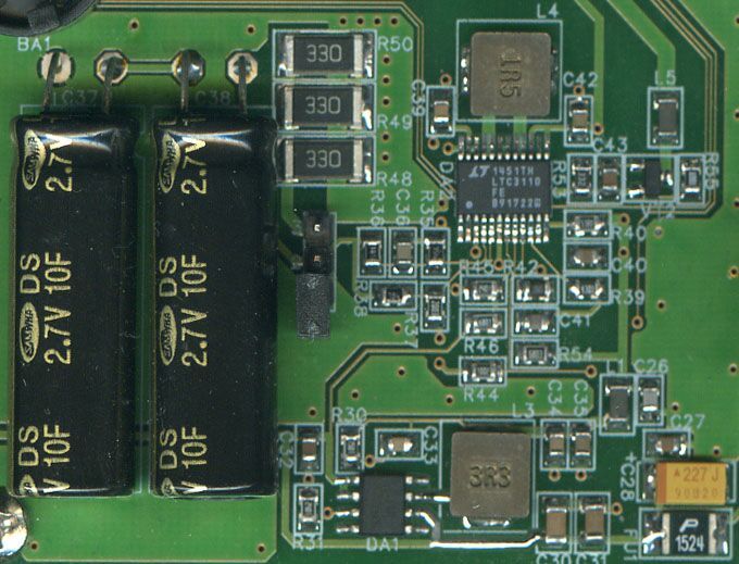
Below I give an image of a printed circuit board with the described circuit, of course, the numbering of the components differs from that indicated on the circuit diagram - it is cross-cutting for the entire box.
If you have questions - please.
The problem arose in front of your humble servant in the following guise: you need to correctly extinguish the Linux OS (running on the Embedded solution) when the external power is turned off. This power was supplied from a standard USB 2.0 port to a previously made box-device through at least a standard USB-B connector. The inexperienced user of this device preferred to pull out the USB cable corny, following the principle of "UnPlug-NoPlay-NoProblem". It is clear that an embedded solution without hard disks and with virtual memory zeroed during configuration is resistant to such force majeure, but a couple of thousand user-hours of operation have shown that it does not always work “without problems”.
I had to wrinkle my brain and go into a creative trance. Upon leaving the trance, the first possible way to solve the problem materialized - the psychological one, which at first seemed the most attractive. The line of thought was approximately as follows - why does the ordinary user jerk a stick sticking in the USB port with an unshakable hand? Probably because neither he himself nor his closest acquaintances lost in this way their thesis, dissertation or annual report. Why the same user did not pull a printer cable from a working printer in the days of ona? Probably because either he saw, or he heard from someone’s lips, how he had to buy a new MB or Centronics on ISA (PCI). I do not want (from the word in general) that my box was pulled out unceremoniously. What needs to be done for this? Correct, form the required user behavior.
I had to shake the skills of circuitry and tracing, and the next version of the box got an RGB LED and a button on the front panel, as well as a piezo signal with a nasty timbre inside. A simple program determined whether the extreme shutdown passed correctly. If it was incorrect and the user's misconduct was the first on her flash memory, then the control action followed: instead of the indicator pleasing yellow and green, the box blinked with a cutting eye red and vilely squealed a couple of minutes before it calmed down and started to load. Relapse was punishable by five minutes, an even more vile heather and a line in the manual that the box, blocked due to repeated incorrect shutdown, is removed from the warranty, here.
You know, the method turned out to be surprisingly effective. But here the Dear Customer put forward a wish that before disconnecting the box would still inform the server that it was taking time from the scene. Now some, but a source of energy was required. The brain from the next creative trance returned with the thought: a lithium-polymer battery is our everything! Common thinking added a lot of skepticism to this thought: I didn’t really want to charge the battery every time I turned it on, because the number of charge-discharges is a consumed resource, as well as the subject of cynical deception by battery manufacturers of innocent customers. Charge not every time you turn it on, but as it discharges? So it is necessary to fence the whole garden, calibrate the battery, measure the voltage on it with good accuracy. In general, yes and then came the stage Samsung Galaxy with its incendiary batteries. Imagining a fire in the place where the box was supposed to stand, I had to voluntarily wave a saber and stop the painful deliberation of the second idea.
Going into a trance for the third time, a creative genius brought to light ionistors. And what, it seems not bad. The capacity is in farads, the number of charge-discharge cycles is not limited, as it were, the volt is really not enough - 2.7 maximum per cell, and they are not very cascaded. There was already nothing to ponder over the lack of options, and again I had to tackle the circuitry together with the trace.
Searching the Internet's vast expanses brought some catch, and, for a moment of thought, it was decided to stop on the Linear LTC3110 microcircuit. Looking ahead, I’ll say that a couple more options have been tested, but not particularly successfully. If the reader is interested in the details of the choice - you are welcome in PM. Of the available options, the LTC3110 contains almost everything you need to build a backup power source on ionistors:
- it has a step-up converter, which makes the designer not particularly limited in the choice of supply voltage;
- this converter uses inductance for energy storage, which significantly increases the efficiency and makes it possible to give a couple of amperes to the load;
- it is possible to limit the current consumed during charging in the range of 125mA - 2A, which is especially important when powered by USB;
- there is a built-in circuit for individual balancing of series-connected ionistors to increase the stored power and reliability;
- the chip is equipped with leads indicating the degree of charge of the ionistors;
- and, for dessert, there is an additional comparator, the thresholds of which are set by the user.
For details and examples of applications, I send the curious Reader to the datasheet on the microcircuit, the almighty Google with the "LTC3110 pdf" spell to help you.
In theory, to build a workable Micro-UPS, the LTC3110 itself needs to add a circuit that provides power to the box in the normal mode, if there is a connection to a working USB. The IC ST1S10PHR was chosen for this honorable role, whose unpretentious disposition and low price have been known and tested for a long time. I also had to add a key that breaks the power supply circuit of the main consumers during the initial charging of the ionistors. This key allows you to solve two problems: firstly, the initial charging time is reduced (since almost everything consumed by USB goes to the ionistors), and secondly, it eliminates the unpleasant possibility of blackout when the UPS is so undercharged that the energy supply is still not enough for the correct one shutdown. Moreover, A “high start” with fully charged ionistors allows the circuit to sometimes (but not very often) consume more current than the USB port can give - the deficit will be replenished from the ionistors. Such a situation may arise, for example, when recording a large block of information on a capacious USB flash drive that is powered along with the box.
I think that the introductory part can be completed on this and move on to a specific work scheme.
This is how the micro-UPS circuit on the ionistors looks.
Power is supplied from the USB 2.0 port (upper left corner of the circuit). On DA1, according to the recommended scheme, a step-down converter 5V -> 3.3V is assembled from a datasheet. Its only feature is an additional filter from high-frequency ringing on L2 and C7. If desired, these elements can be excluded. Resistors R3 ... R5 are used for emergency discharge of ionistors before transportation, for example, or before setting up the entire board as a whole, otherwise the power source remains on it, and powerful enough to burn anything. The discharge resistors are connected or disconnected by jumper SA1. VT1, C16, R17 and R18 - the key to power the main consumers, it has already been mentioned above and will have to add a few words below. Everything else is the standard LTC3110 harness from the datasheet.
3V3SBY is the standby power of the control circuit, in the box it is implemented on the CPLD EPM240T100 from Altera, but nothing prevents it from being executed on a microcontroller or discrete logic. 3V3 is the main power supply of the box reserved by UPS. Micro-UPS status information is displayed on PWRFAIL, BATFULL and BATLOW with self-explanatory names. PWRFAIL is activated when there is a loss of power from USB, BATFULL indicates that the charge reaches the level of 95% (5.2V), BATLOW shows a decrease in charge level to 40% (2.1V). If desired, this level can be adjusted by selecting R6 and R7, guided by the datasheet. Unfortunately, such a trick does not work with the BATFULL level - it is hammered into the IC with nails.
The micro UPS controls two signals: PWRON and BATOFF. PWRON turns on the main power, BATOFF turns off the UPS as a whole.
The general logic of micro UPS operation is as follows:
- in the initial state, C8 and C9 are completely discharged, jumper SA1 in the left position, 5V USB power is not supplied;
- the device is plugged into a USB-B 2.0 port;
- the converter on DA1 starts supplying current to the 3V3SBY line, energizing the control circuit on CPLD, which, in turn, opens the VT1 key, removing the PWRON signal; in addition, the control circuit removes the BATOFF signal, including DA2;
- DA2 begins to charge the ionistors; as they charge, the BATLOW signal is deactivated (at 2.1 V), then BATFULL is activated (at 5.2 V on ionistors);
- the appearance of the BATFULL signal, the control circuit regards the readiness of the micro UPS to work, and turns on VT1, supplying power to the main circuit; At the same time, DA2 continues to monitor the ionistors, and when the charge drops below 95%, it starts charging; connecting VT1 to the RSENS DA2 pin ensures that such a current is taken to recharge that it does not exceed the USB limit, taking into account the consumed main circuit; if the consumption of the main circuit exceeds this limit, the discharge of ionistors will begin to compensate for unnecessary expenses;
- when disconnecting 5V USB, the PWRFAIL line is activated, letting the control device know that the external source has disappeared; the control circuit generates a request for interrupting the ARM processor to run the correct shutdown script; all this time the power is supplied by DA2;
- upon completion of the shutdown procedure, ARM issues a signal that everything is ready for extinction, and the control circuit sets BATOFF, disabling DA2; in this state, the box is located before power is supplied to the 5V USB (see point 1 except for the residual charge on C8 and C9);
- if ARM hesitated a lot and was unable to close everything until the BATLOW signal, the circuit will have to be de-energized by force.
If you wish, it is easy to organize any other micro-UPS control logic, for example, by increasing the BATLOW enable level to 60% (selecting R6 and R7), use it as a signal to stop, disconnecting by force from the full discharge C8 and C9.
In the end, quickly go over the configurable parameters of the circuit. R1 and R2 determine the output voltage of DA1, another voltage may require the replacement of C1, C2, C4-C6 and L1. The ratings of C8 and C9 determine only the times of charging and discharging the UPS, I personally tried from 4.7 to 100 Farads, theoretically there are no restrictions. R6 and R7 determine the activation level of BATLOW. The voltage of the maximum charge of the ionistors depends on the ratio R8 / R9. R11 determines the current consumed from 5V USB, at the indicated resistance, the circuit consumes 0.5A. The R12 / R14 ratio sets a drop level of 5V USB, which will be defined as power failure (PWRFAIL). R15 / R16 determines the output voltage of DA2 in discharge mode.
The output signals of the LTC3110 are made according to the "open drain" scheme so as not to be tied to a specific supply voltage. In my circuit, pull-up resistors for them are involved in CPLD, it is not a problem to use them in any modern microcontroller. Well, if you decide to assemble a control circuit on K155, then you have to take care of the resistors yourself.
A few words about the C16. Obtaining this knowledge took me the most time spent on the UPS prototype board. After all, what is the problem? In the datasheet, black in English says that if you want the sum of the current consumed by the main circuit and the charging current of the ionistors to be guaranteed not to exceed the limit set by R11, please kindly power the main circuit from the RSENS output. OK, agreed. And then more interesting. Since your circuit can have anything, up to a short circuit (short circuit, it is a short circuit, it is short), says the datasheet, the LTC3110 is equipped with a special protection circuit. OK, very nice. And now for the fun part. We read the datasheet further: and so that the protection scheme is not mistaken, please, provide the total capacity of the power line NOT MORE, Karl, 10 microFarads. Goofy ... For everything about everything, and do not deny yourself anything. And really any load greater than 10uF when connected wedges ... Do not be deceived, Basurman. I had to make a slight delay in the key on VT1, which gives C16. I understand that for some time VT1 will not be in the key mode, but between heaven and earth (in the sense, between VCC and GND), which is not great at all. But at least it works. Such is the "new hawa." For zealots of the purity of key modes, I’ll add that I tried not to put C16, but an inductance of 1.5 μH in series with VT1 - everything works great.
Below I give an image of a printed circuit board with the described circuit, of course, the numbering of the components differs from that indicated on the circuit diagram - it is cross-cutting for the entire box.
If you have questions - please.