Operator Panel (HMI) with I2C Bus for Arduino
- Tutorial
As part of working with some kind of arduino-compatible equipment (about him at the end) I needed a screen with buttons to control and display current information. That is, the operator panel was needed, it is HMI.
It was decided to make the HMI independently, and use the “square” i2c bus as the interface.
If you are interested in the process of developing and programming such devices, welcome to Cat.
Specifications:
There will be obvious questions:


1. Self-made interconnect board with DB9F connector. So, as the power supply + 5V for the port and display extenders is taken from the Arduino, we put a fuse of 0.1 A. on the board.
2. We all know the well-known display 1602 with the soldered FC-113 board, which connects the display to the i2c bus.
3. A homemade keyboard board with a PCF8574P chip that will read the states of the buttons and transfer them over the i2c bus. By the way, the FC-113 “display” board is also based on the PCF8574 microcircuit, only with the T index, i.e. planar, not DIP, like PCF8574P.
I put the buttons 12x12mm with a square pusher; you can wear large multicolored caps on them.
It should say a few words about the PCF8574P microcircuit, on the basis of which I made a keyboard board.
The PCF8574P is an i2c port extender. In total there are 8 ports, each of which can be configured to work as an input or output. For this chip and strapping as such is not required (remember, for example, max232), I just in case put a capacitor on the power supply.
The address of the PCF8574P chip is set with the help of the address legs A0, A1, A2, which pull up to the ground or to the power through a 10 kΩ resistor.
On the keyboard board, I put all the address feet of the PCF8574P on the ground, so the address is hard-coded as 0x20 and cannot be changed.
As I already wrote, I chose the DB9F as the connector for the HMI. Arduino receives signals from it +5 V, GND, SDA, SCL.

The wire for communication on i2c Arduino and HMI made 1.4 m long, works without glitches.
He drew the boards in Sprint Layout 6, transferred it by LUT to textolite and etched it in a solution of peroxide and citric acid.
The case made a friend of plexiglass 4 mm on a laser cutting machine.
From the point of view of Arduino, this HMI consists of 2 devices that work on the i2c bus: a display (LCD) with the address 0x27 and a keyboard with the address 0x20. Accordingly, the Arduino will work separately with the keyboard and separately with the LCD.
Working with LCD is carried out through the special library “LiquidCrystal_I2C.h”, it needs to be installed in the Aduino IDE.
The keyboard is handled through the standard Wire.h library, which is originally available in the Aduino IDE.
Connect HMI to Ardiuno.

1. First, check to see if Arduino sees our HMI. To do this, we load into it a program that will scan the i2c bus for the presence of devices on it.
During the execution of this program, Arduino will write the results of the i2c bus scan to the serial port. To view this data, go to Tools-> Port Monitor in the Arduino IDE.

We see that Arduino on the i2c bus has identified two devices with addresses 0x20 and 0x27, this is the keyboard and LCD, respectively.
2. Now let's see how our keyboard works. Create a program that will poll the state of the buttons and display it on the LCD.

The keyboard works.
3. Finally, you can move on to what it was all about — the creation of a multi-level menu in Arduino. Through the menu we will not only look at the information, but also manage the outputs of the Arduino itself.

Nete has a lot of information on creating a multi-level menu in C ++, and even saw some libraries for Arduino. But I decided in my program to write the menu myself. First, the smaller the left libraries in the project, the calmer. And secondly, it is simple.
I got another variation of the tree menu. The menu allows to display in each line both static text and a variable value. For example, you can display the name of the parameter and its value.
To display variables on the screen, I apply the principle of tags - in a certain way decorated text labels in the text, instead of which, when the text is displayed, a value is displayed on the screen.
Parameters can be changed by pressing the “Edit” button. Moreover, the tag of each parameter indicates whether it is available for editing or only for reading. If the current parameter is read-only, at the beginning of the line the pointer will be '*', if editing the parameter is allowed, the pointer will become '+'.
Separately, you need to address the issue of Russification.
In the character generator of some LCD 1602 there are no Russian letters, and instead of them are Japanese crooked stitches. It is impossible to reflash the character generator. Therefore, it is necessary either to write words on the screen in Latin letters, or in the program to form Russian letters yourself, since LCD 1602 has the ability to create and store your own characters in the LCD RAM. But, in the latter case, you can display no more than eight "self-made" characters at a time.
In principle, there is nothing terrible if you write Russian words in LCD in English letters. Vaughn, even the venerable French company Shneider Electric (the same one that sold howitzers to the king before the revolution) for a decade and a half did not allow herself to introduce Russian into their famous Zelio programmable relays. But this does not prevent them from actively trading in the entire CIS. Moreover, the channels, Spanish and Portuguese have entered.
At many of our factories, these Zelio communicate with staff with phrases like “NASOS 1 VKL”.
When it is not clear whether there are Russian letters in a particular LCD, you need to display all the characters of its character generator. If there is a Cyrillic alphabet, it starts with the 160 position.
But even if your LCD 1602 is Russified, displaying Russian words is not so easy. At least using the “LiquidCrystal_I2C.h” library when working with LCDs on the i2c bus.
If you simply display the Russian text, for example, the lcd.print instruction (“Hello !!!”), then instead of “Hello !!!” some kind of rubbish will appear on the screen.
This is because the Russian letters Arduino IDE translates into double-byte UTF-8 code, and in the LCD all single-byte characters.
The same problem, by the way, is observed when transferring Russian texts from Arduino to the monitor of the Arduino IDE port. Arduino transmits Russian letters in a two-byte UTF-8 encoding to the serial port, and the Arduino IDE port monitor tries to read them in the single-byte Windows-1251 encoding (cp1251). Although cp1251 is also 8-bit, as is the LCD 1602 encoding, but it does not match it.
You can create Russian texts through character codes. For example, the line "LCD display" on the Russified LCD will be displayed as follows:
But I do not like this approach.
In order to correctly display the Russian text on the Russified LCD 1602, several libraries were invented for Arduino. But after reading the reviews, I saw that many complain about glitches when using them.
Therefore, in my multi-level menu program I myself wrote a simple function to transform UTF-8 into LCD codes. True, he did it only for the capital Russian letters, which suits me perfectly.
On this about homemade HMI with i2c bus, I have everything.
Oh yeah, at the beginning of the article I wrote that I was doing HMI not entirely for Arduino, but for arduino-compatible equipment. This is me about the CONTROLLINO MAXI PLC , which is programmed from the Arduino IDE (and many others).

CONTROLLINO MAXI is actually an Arduino + a bunch of shields and everything is designed as an industrial PLC. But about him next time.
Links
→ Archive with layouts, sketches and a printed circuit board in lay6 format
→ Arduino-compatible СONTROLLINO PLC , the work with which inspired the creation of HMI i2c
→ PCF8574 port extender and its connection to Arduino
→ FC-113 boardto operate LCD 1602 via i2c bus and connect it to Arduino
→ Multi-level tree menu , general principles of C creation
→ UTF-8 encoding
→ Windows-1251 encoding
It was decided to make the HMI independently, and use the “square” i2c bus as the interface.
If you are interested in the process of developing and programming such devices, welcome to Cat.
Specifications:
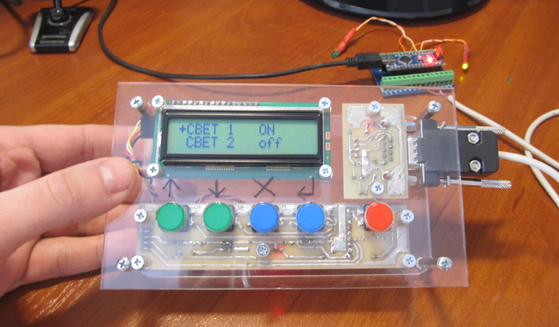
- Display 1602, monochrome 16x2 characters
- 5 buttons: up, down, cancel, enter, edit
- I2c interface
- DB9F Connector
- Dimensions 155x90x44 mm
There will be obvious questions:
Why not buy ready shild?
Конечно, можно было у тех же китайцев купить готовый шилд c дисплеем и клавиатурой и типа такого:

К этому шилду можно припаять 2 платки FC-113 и получится функционально то же самое, что и у меня: дисплей с клавиатурой, работающие по i2c. Цена набора составит от 4$.
Но на этой плате меня не устраивает размер кнопок, а мне хотелось большие, с возможностью установки разноцветных колпачков. Подключать Arduino к HMI мне хотелось не на соплях, а через нормальный разъем DB9F, а значит нужно было делать соединительную плату. А в этом случае какая разница, делать одну плату или две? Кроме того, у меня уже было в запасе несколько дисплеев 1602, а потому мне нужно было потратить всего 1.02$ для покупки на Алиэкспресс платы FC-113 (0.55$) и расширителя портов PCF8574P (0.47$).
Ну а самое главное- если имеешь дело с Ардуино, то самостоятельное изготовление шилдов для него это само собой разумеющееся дело, правда ведь?
Why bus i2c, is not it easier to connect the buttons directly?
В сфере АСУ ТП, где я работаю, HMI для связи с устройствами используют интерфейсы цифровой передачи данных RS-232,RS-485, CAN и т.д. Поэтому для меня логично, что моя самодельная HMI будет вся работать по интерфейсу передачи данных, в данном случае по i2c.
Если бы я смастерил устройство, где дисплей работает по квадратной шине, а кнопки идут напрямую на входа Ардуино, это бы вызывало у меня чувство глубокого неудовлетворения. Как представлю эту картину: из панели торчит отдельно шнурок на интерфейс, отдельно провода на входа, брррр…
Кроме того, различие между платой кнопок, которые идут напрямую ко входам Ардуино, и платой кнопок с интерфейсом i2c, заключается только в микросхеме PCF8574P(0.47$), конденсаторе и двух резисторах.
Why are the buttons located so and not otherwise?
Кнопки у меня слева направо имеют такие функции: вверх, вниз, отмена, ввод, редактирование.
Кнопка «редактирование» отнесена от остальных чуть в сторону для акцентирования своей функции- изменение значений логических параметров(вкл/выкл) или переход в режим редактирования в случае параметров числовых.
Всего кнопок 5, хотя микросхема на плате клавиатуры позволяет подключить до 8 штук.
Достаточно было бы обойтись четырьмя кнопками и функционал бы не пострадал- «ввод» и «редактирование» можно совместить в одной кнопке. Но мне просто жалко стало, что из 8 ног микросхемы расширителя порта половина будет не задействована.
Еще отдельная кнопка «редактирование» может быть полезна, если я решу в одной строке выводить несколько параметров. Тогда этой кнопкой можно будет переключаться между параметрами, указывая, какой именно из них нужно изменить. Примерно так работает кнопка «SET» в популярных китайских HMI OP320.
Если первые две кнопки означают вверх и вниз, то почему бы их не разместить вертикально, как, например, сделано в указанном выше китайском шилде?
Лично для меня удобнее, когда все кнопки находятся по горизонтали, тогда во время работы пальцы перемещаются только в одной плоскости.
Iron
1. Self-made interconnect board with DB9F connector. So, as the power supply + 5V for the port and display extenders is taken from the Arduino, we put a fuse of 0.1 A. on the board.
2. We all know the well-known display 1602 with the soldered FC-113 board, which connects the display to the i2c bus.
3. A homemade keyboard board with a PCF8574P chip that will read the states of the buttons and transfer them over the i2c bus. By the way, the FC-113 “display” board is also based on the PCF8574 microcircuit, only with the T index, i.e. planar, not DIP, like PCF8574P.
I put the buttons 12x12mm with a square pusher; you can wear large multicolored caps on them.
Photos and homemade circuit boards


It should say a few words about the PCF8574P microcircuit, on the basis of which I made a keyboard board.
The PCF8574P is an i2c port extender. In total there are 8 ports, each of which can be configured to work as an input or output. For this chip and strapping as such is not required (remember, for example, max232), I just in case put a capacitor on the power supply.
The address of the PCF8574P chip is set with the help of the address legs A0, A1, A2, which pull up to the ground or to the power through a 10 kΩ resistor.
On the keyboard board, I put all the address feet of the PCF8574P on the ground, so the address is hard-coded as 0x20 and cannot be changed.
As I already wrote, I chose the DB9F as the connector for the HMI. Arduino receives signals from it +5 V, GND, SDA, SCL.
The wire for communication on i2c Arduino and HMI made 1.4 m long, works without glitches.
He drew the boards in Sprint Layout 6, transferred it by LUT to textolite and etched it in a solution of peroxide and citric acid.
Little about etching
В сети есть много рецептов травления лимонной кислотой плат на фольгированном стеклотекстолите.
Я делал такой раствор: 100 мл перекиси водорода 3%, 50 г лимонной кислоты, 3 чайные ложки соли. Баночку с перекисью подогрел в кастрюле с водой до температуры где-то 70 градусов.
Погружаем плату в раствор рисунком вниз, как рекомендуют при травлении перекисью.
Через пару десятков секунд начинается бурный процесс. Выделяется много пара, вдыхать который не рекомендуется. Наверное.

Потом процесс стихает. Переворачиваем плату.

Готово.

Я делал такой раствор: 100 мл перекиси водорода 3%, 50 г лимонной кислоты, 3 чайные ложки соли. Баночку с перекисью подогрел в кастрюле с водой до температуры где-то 70 градусов.
Погружаем плату в раствор рисунком вниз, как рекомендуют при травлении перекисью.
Через пару десятков секунд начинается бурный процесс. Выделяется много пара, вдыхать который не рекомендуется. Наверное.
Потом процесс стихает. Переворачиваем плату.
Готово.
The case made a friend of plexiglass 4 mm on a laser cutting machine.
Lyrical digression about the corps
Купить готовый корпус или сделать самому? Немного подумав, решил делать сам. Те, что видел в продаже, мне не подходили или по цене, или по эстетическим соображениям, или были на DIN-рейку, что тоже меня не устраивало.
Изначально корпус хотел выпилить из фанеры. Но потом вспомнил, что у меня есть замечательный друг и, по большой для меня радости, директор фирмы по производству спортивных наград. У него имеются всякие там станки, в том числе и для лазерной резки.
Обратился за помощью и друг не отказал- за пару минут лазером нарезали деталей.
Пользуясь случаем, хочу сказать, спасибо тебе, Коля! Иначе мне пришлось бы еще целый день пилить и шлифовать фанеру, а результат едва бы был таким блистательным.
Programming
From the point of view of Arduino, this HMI consists of 2 devices that work on the i2c bus: a display (LCD) with the address 0x27 and a keyboard with the address 0x20. Accordingly, the Arduino will work separately with the keyboard and separately with the LCD.
Working with LCD is carried out through the special library “LiquidCrystal_I2C.h”, it needs to be installed in the Aduino IDE.
The keyboard is handled through the standard Wire.h library, which is originally available in the Aduino IDE.
Connect HMI to Ardiuno.
1. First, check to see if Arduino sees our HMI. To do this, we load into it a program that will scan the i2c bus for the presence of devices on it.
Sketch 1, i2c tire scan
//i2c_scaner
#include <Wire.h>
String stringOne;
void setup()
{
  Wire.begin();
  Serial.begin(9600);
  while (!Serial);
}
voidloop()
{
  byte error, address;
  int nDevices;
  Serial.println("Scanning...");
  nDevices = 0;
  for(address = 1; address < 127; address++ )
  {
    Wire.beginTransmission(address);
    error = Wire.endTransmission();
if (error == 0)
  {
  String stringOne =  String(address, HEX);
  Serial.print("0x");     Serial.print(stringOne); Serial.print(" - ");
    if(stringOne=="0A") Serial.println("'Motor Driver'");
    if(stringOne=="0F") Serial.println("'Motor Driver'");
    if(stringOne=="1D") Serial.println("'ADXL345 Input 3-Axis Digital Accelerometer'");
    if(stringOne=="1E") Serial.println("'HMC5883 3-Axis Digital Compass'");
    if(stringOne=="5A") Serial.println("'Touch Sensor'");
    if(stringOne=="5B") Serial.println("'Touch Sensor'");
    if(stringOne=="5C") Serial.println("'BH1750FVI digital Light Sensor' OR 'Touch Sensor"  );
    if(stringOne=="5D") Serial.println("'Touch Sensor'");
    if(stringOne=="20") Serial.println("'PCF8574 8-Bit I/O Expander' OR 'LCM1602 LCD Adapter' ");
    if(stringOne=="21") Serial.println("'PCF8574 8-Bit I/O Expander'");
    if(stringOne=="22") Serial.println("'PCF8574 8-Bit I/O Expander'");
    if(stringOne=="23") Serial.println("'PCF8574 8-Bit I/O Expander' OR 'BH1750FVI digital Light Sensor'");
    if(stringOne=="24") Serial.println("'PCF8574 8-Bit I/O Expander'");
    if(stringOne=="25") Serial.println("'PCF8574 8-Bit I/O Expander'");
    if(stringOne=="26") Serial.println("'PCF8574 8-Bit I/O Expander'");
    if(stringOne=="27") Serial.println("'PCF8574 8-Bit I/O Expander' OR 'LCM1602 LCD Adapter '");
    if(stringOne=="39") Serial.println("'TSL2561 Ambient Light Sensor'");
    if(stringOne=="40") Serial.println("'BMP180 barometric pressure sensor'"    );
    if(stringOne=="48") Serial.println("'ADS1115 Module 16-Bit'");
    if(stringOne=="49") Serial.println("'ADS1115 Module 16-Bit' OR 'SPI-to-UART'");
    if(stringOne=="4A") Serial.println("'ADS1115 Module 16-Bit'");
    if(stringOne=="4B") Serial.println("'ADS1115 Module 16-Bit'");
    if(stringOne=="50") Serial.println("'AT24C32 EEPROM'");
    if(stringOne=="53") Serial.println("'ADXL345 Input 3-Axis Digital Accelerometer'");
    if(stringOne=="68") Serial.println("'DS3231 real-time clock' OR 'MPU-9250 Nine axis sensor module'");
    if(stringOne=="7A") Serial.println("'LCD OLED 128x64'");
    if(stringOne=="76") Serial.println("'BMP280 barometric pressure sensor'");
    if(stringOne=="77") Serial.println("'BMP180 barometric pressure sensor' OR 'BMP280 barometric pressure sensor'");
    if(stringOne=="78") Serial.println("'LCD OLED 128x64'" );
   nDevices++;
  }
    elseif (error==4)
    {
      Serial.print("Unknow error at address 0x");
      if (address<16)
        Serial.print("0");
      Serial.println(address,HEX);
    }
  }
  if (nDevices == 0)
    Serial.println("No I2C devices found\n");
  elseSerial.println("done\n");
  delay(5000);
}
During the execution of this program, Arduino will write the results of the i2c bus scan to the serial port. To view this data, go to Tools-> Port Monitor in the Arduino IDE.
We see that Arduino on the i2c bus has identified two devices with addresses 0x20 and 0x27, this is the keyboard and LCD, respectively.
2. Now let's see how our keyboard works. Create a program that will poll the state of the buttons and display it on the LCD.
Sketch 2, displaying the status of buttons
/*
Вывод на LCD состояния кнопок по шине i2c
LCD подключен через плату FC-113, адрес 0x27
Клавиатура подключена через расширитель портов PCF8574P, адрес 0x20
*/#include<LiquidCrystal_I2C.h>#include<Wire.h>#define   led   13#define   ADDR_KBRD  0x20#define   ADDR_LCD   0x27
byte dio_in;
bool b;
bool key[5];
LiquidCrystal_I2C lcd(ADDR_LCD,16,2);  // Устанавливаем дисплейvoidsetup(){
pinMode(led, OUTPUT);
//
  lcd.init();
  lcd.backlight();// Включаем подсветку дисплея//
  Wire.begin();
  Wire.beginTransmission(ADDR_KBRD);
  Wire.write(B11111111); //Конфигурация всех порты PCF8574P на клавиатуре как входа
  Wire.endTransmission();
}
voidloop(){
  Wire.requestFrom(ADDR_KBRD,1);
  while (!Wire.available());
  byte dio_in = Wire.read();  //читаем состояние портов PCF8574P(кнопок)//заполняем массив кнопок значениями их состояний
  byte mask=1;
  for(int i=0; i<5;i++)
  {
    key[i]=!(dio_in & mask);
    mask=mask<<1;
   }
  b=!b;
  digitalWrite(led, b); //Мигаем светодиодом на Ардуино//Вывод состояний кнопок на LCD
  lcd.setCursor(0, 0);
  lcd.print(String(key[0])+" "+
            String(key[1])+" "+
            String(key[2])+" "+
            String(key[3])+" "+
            String(key[4])+" ");
  delay(100);
}
The keyboard works.
3. Finally, you can move on to what it was all about — the creation of a multi-level menu in Arduino. Through the menu we will not only look at the information, but also manage the outputs of the Arduino itself.
Nete has a lot of information on creating a multi-level menu in C ++, and even saw some libraries for Arduino. But I decided in my program to write the menu myself. First, the smaller the left libraries in the project, the calmer. And secondly, it is simple.
I got another variation of the tree menu. The menu allows to display in each line both static text and a variable value. For example, you can display the name of the parameter and its value.
To display variables on the screen, I apply the principle of tags - in a certain way decorated text labels in the text, instead of which, when the text is displayed, a value is displayed on the screen.
Parameters can be changed by pressing the “Edit” button. Moreover, the tag of each parameter indicates whether it is available for editing or only for reading. If the current parameter is read-only, at the beginning of the line the pointer will be '*', if editing the parameter is allowed, the pointer will become '+'.
Sketch 3, multi-level menu
/*
Древовидное меню, работа снопками и LCD по шине i2c
LCD подключен через плату FC-113, адрес 0x27
Клавиатура подключена через расширитель портов PCF8574P, адрес 0x20
*/#include <LiquidCrystal_I2C.h>#include <Wire.h>#define   led   13     //светодиод на плате Ардуно нано; будет мигать, показывая этим, что система не зависла #define   ADDR_KBRD  0x20   #define   ADDR_LCD   0x27#define   PORT_D2    2 #define   PORT_D3    3#define   PORT_D4    4#define    POINT_ON_ROOT_MENU_ITEM   0   // 0/1= запретить/разрешить вывод указателя позиции(* или +) на главном экране менюbyte dio_in;
bool b;
byte i;
//bool переменные, которыми можно управлять из менюbool  BoolVal[9]={0,0,0, 0,0,0, 0,0,0};
#define  ValSvet1 BoolVal[0]#define  ValSvet2 BoolVal[1]#define  ValSvet3 BoolVal[2]#define  ValRozetka1 BoolVal[3]#define  ValRozetka2 BoolVal[4]#define  ValRozetka3 BoolVal[5]#define  ValClapan1 BoolVal[6]#define  ValClapan2 BoolVal[7]#define  ValClapan3 BoolVal[8]//struct STRUCT_KEY{
  bool StateCur;  //Текущее состояние кнопки  bool StateOld;  //Состояние кнопки при прошлом опросеbool Imp;       //Было нажатие кнопки (переход из 0 в 1)
  };
//кнопки
STRUCT_KEY Key[5]={0,0,0,
            0,0,0,
            0,0,0,
            0,0,0,
            0,0,0
           };
//---/*Текстовые строки меню
 * Допустимы теги, например:
 * '#A1'  bool переменная, где
 * '#'- тип переменной bool,
 * 'A'- адрес(HEX) переменной в массиве BoolVal,
 * '1'- редактирование переменной разрешено
 * при выводе текста, вместо тега автоматически подставляется значение переменной
 */
String StrNull=" ";      //пустая строка
String StrRoot1="COMP-MAN.INFO";
String StrRoot2="PLC-BLOG.COM.UA";
String StrSvet= "СВЕТ";      //Свет
 String StrSvet1="СВЕТ 1   #01";
 String StrSvet2="СВЕТ 2   #10";
 String StrSvet3="СВЕТ 3   #21";
String StrRozetka="РОЗЕТКИ";    //Розетки
 String StrRozetka1="РОЗЕТКА 1  #30";
 String StrRozetka2="РОЗЕТКА 2  #40";
 String StrRozetka3="РОЗЕТКА 3  #50";
String StrClapan="КЛАПАНЫ";       //Клапаны
 String StrClapan1="КЛАПАН 1  #60";    //
 String StrClapan2="КЛАПАН 2  #70";
 String StrClapan3="КЛАПАН 3  #80";
struct MENU_ITEM      //Пункт меню(экран), состоит из 2 строк и координат перехода при нажатии кнопок
  {
    byte KeyUp;       //№ пункта меню, куда переходить по кнопке "вверх"byte KeyDwn;      //№ пункта меню, куда переходить по кнопке "вниз"byte KeyCancel;   //№ пункта меню, куда переходить по кнопке "отмена"(cancel)byte KeyEnter;    //№ пункта меню, куда переходить по кнопке "ввод"(enter)byte KeyEdit;     //кнопка "edit", резерв
    String *pstr1;    //указатель на верхнюю строку меню(экрана)
    String *pstr2;    //указатель на нижнюю строку меню(экрана)
  };
//
MENU_ITEM  Menu[]={0,0,0,1,0,  &StrRoot1,&StrRoot2,               //0  Главный экран1,8,0,2,0, &StrSvet,&StrRozetka,             //1  СВЕТ2,3,1,2,0, &StrSvet1,&StrSvet2,              //22,4,1,3,0, &StrSvet2,&StrSvet3,              //33,4,1,4,0, &StrSvet3,&StrNull,               //40,0,0,0,0, &StrNull,&StrNull,                //5  РЕЗЕРВ0,0,0,0,0, &StrNull,&StrNull,                //60,0,0,0,0, &StrNull,&StrNull,                //71,15,0,9,0, &StrRozetka,&StrClapan,          //8   РОЗЕТКИ9,10,8,9,0,  &StrRozetka1, &StrRozetka2,     //9 9,11,8,10,0, &StrRozetka2, &StrRozetka3,     //1010,11,8,11,0, &StrRozetka3, &StrNull,        //11                        0,0,0,0,0, &StrNull,&StrNull,                //12 РЕЗЕРВ0,0,0,0,0, &StrNull,&StrNull,                //130,0,0,0,0, &StrNull,&StrNull,                //148,15,0,16,0,  &StrClapan, &StrNull,          //15   КЛАПАНЫ16,17,15,0,0,  &StrClapan1,&StrClapan2,      //1616,18,15,0,0,  &StrClapan2,&StrClapan3,      //1717,18,15,0,0,  &StrClapan3,&StrNull,         //180,0,0,0,0, &StrNull,&StrNull,                //19  РЕЗЕРВ0,0,0,0,0, &StrNull,&StrNull,                //200,0,0,0,0, &StrNull,&StrNull,                //21
                    };
byte PosMenu=0;   //позиция менюLiquidCrystal_I2C lcd(ADDR_LCD,16,2);  // Устанавливаем дисплей//Чтение состояний кнопокvoidReadKey(byte dio_in)
{
  //заполняем массив кнопок значениями их состоянийbyte mask=1;
  for(i=0; i<5; i++)
  {
    Key[i].StateCur=!(dio_in & mask);
    mask=mask<<1;
    Key[i].Imp=!Key[i].StateOld & Key[i].StateCur;    //определяем нажатие кнопки (переход из 0 в 1)
    Key[i].StateOld=Key[i].StateCur;
   }
}
/*
 *  Перекодировка UTF-8 русских букв (только заглавных) в коды LCD
 * а то Ардуино выводит их неправильно
 */byte  MasRus[33][2]= {
                      144,  0x41,   //А145,  0xa0,
                      146,  0x42,
                      147,  0xa1,
                      148,  0xe0,
                      149,  0x45,
                      129,  0xa2,
                      150,  0xa3,
                      151,  0xa4,
                      152,  0xa5,
                      153,  0xa6,
                      154,  0x4b,
                      155,  0xa7,
                      156,  0x4d,
                      157,  0x48,
                      158,  0x4f,
                      159,  0xa8,
                      160,  0x50,
                      161,  0x43,
                      162,  0x54,
                      163,  0xa9,
                      164,  0xaa,
                      165,  0x58,
                      166,  0xe1,
                      167,  0xab,
                      168,  0xac,
                      169,  0xe2,
                      170,  0xad,
                      171,  0xae,
                      172,  0xc4,
                      173,  0xaf,
                      174,  0xb0,
                      175,  0xb1//Я
  };
String RusStrLCD(String StrIn)
{
  String StrOut="";
  byte b1;
  byte y;
  byte l=StrIn.length();
  for(byte i=0; i<l; i++)
   {
    b1=StrIn.charAt(i);
    if (b1<128)
     StrOut=StrOut+char(b1);
    else
    {
      if (b1==208)      //байт==208, это первый байт из 2-байтного кода рус. буквы
      {
        b1=StrIn.charAt(i+1);
        for(y=0; y<33; y++)
         if(MasRus[y][0]==b1)
          {
            StrOut=StrOut+char(MasRus[y][1]);
            break;
          }
        }
       i++;
     }
   }
  return StrOut;
}
//--------------------------- //ASCII HEX ---> decbyteStrHexToByte(char val)
{
    byte dec=0;
    switch (val) {
    case'0':
      dec=0;
      break;
    case'1':
      dec=1;
      break;
    case'2':
      dec=2;
      break;
    case'3':
      dec=3;
      break;
    case'4':
      dec=4;
      break;
    case'5':
      dec=5;
      break;
    case'6':
      dec=6;
      break;
    case'7':
      dec=7;
      break;
    case'8':
      dec=8;
      break;
    case'9':
      dec=9;
      break;
    case'A':
      dec=10;
      break;
    case'B':
      dec=11;
      break;
    case'C':
      dec=12;
      break;
    case'D':
      dec=13;
      break;
    case'E':
      dec=14;
      break;
    case'F':
      dec=15;
      break;
    default:
    dec=0;
    break;
  }
return dec;
}
//Вывод на экран пункта менюvoidWriteLCD(byte num)
{
   String str[]={"*"+*Menu[num].pstr1,*Menu[num].pstr2};
  if (num==0 && POINT_ON_ROOT_MENU_ITEM==0)  //на главном эркане нужно выводить указатель?
   str[0].setCharAt(0,' ');                  //стираем указатель, если нет //Подставляем значения переменных вместо теговbyte NumVal;
  byte l;
  for(byte y=0; y<2; y++)
  {
  l=str[y].length();
  for(i=0; i<l; i++)
  {
   if (str[y].charAt(i)=='#')  //# bool, состояния off/ON
    {
      if(StrHexToByte(str[y].charAt(i+2))==1 && y==0)   //редактирование параметра разрешено?
        str[y].setCharAt(0,'+');
      NumVal=StrHexToByte(str[y].charAt(i+1));
      str[y]=str[y].substring(0,i)+String(NumVal) ;
      if(BoolVal[NumVal]==0)
        str[y]=str[y].substring(0,i)+"off" ;
      if(BoolVal[NumVal]==1)
        str[y]=str[y].substring(0,i)+"ON" ;
    }
   if (str[y].charAt(i)=='$') //$ int, делается по тому же принципу, но мне пока не надо
    {
      ;
    }
   if (str[y].charAt(i)=='~') //~ время, делается по тому же принципу, но мне пока не надо
    {
      ;
    }
  }
  }
  //---
  lcd.clear();
  lcd.setCursor(0, 0);
  lcd.print(str[0]);
  lcd.setCursor(1, 1);
  lcd.print(str[1]);
}
//Определяем, на какой пункт меню нужно перейтиbyteGoMenu(byte key)
{
  byte PosMenuNew=PosMenu;
  switch (key) {
    case0:
      PosMenuNew=Menu[PosMenu].KeyUp;
      break;
    case1:
      PosMenuNew=Menu[PosMenu].KeyDwn;
      break;
    case2:
      PosMenuNew=Menu[PosMenu].KeyCancel;
      break;
    case3:
      PosMenuNew=Menu[PosMenu].KeyEnter;
      break;
    case4:
      ;
      break;
    default:
    break;
  }
  return PosMenuNew;
}
//действия по нажатию кнопки "Edit"voidEdit(byte posmenu)
{
  byte NumVal;
  bool  *pval;
  String str=*Menu[posmenu].pstr1;
  byte l=str.length();
  for(i=0; i<l; i++)
   if (str.charAt(i)=='#')       //#- bool, состояние off/ON
    {
       if(StrHexToByte(str.charAt(i+2))==1)   //редактирование параметра разрешено?
       {
          pval= &(BoolVal[StrHexToByte(str.charAt(i+1))]);    //находим параметр, который привязан к тек. пункту меню
          *pval=!(*pval);                     //меняем значение параметра на противоположное
       }
    }
}
//Вывод данные в порты АрдуиноvoidValToPort()
{
 digitalWrite(PORT_D2,ValSvet1);
 digitalWrite(PORT_D3,ValSvet2);
 digitalWrite(PORT_D4,ValSvet3);
}
voidsetup()
{
pinMode(led, OUTPUT); //светодиод на плате Ардуино нано
pinMode(PORT_D2, OUTPUT);
pinMode(PORT_D3, OUTPUT);
pinMode(PORT_D4, OUTPUT);
//Перекодируем русские тексты для LCD
StrSvet=RusStrLCD(StrSvet);
 StrSvet1=RusStrLCD(StrSvet1);
 StrSvet2=RusStrLCD(StrSvet2);
 StrSvet3=RusStrLCD(StrSvet3);
StrRozetka=RusStrLCD(StrRozetka);
 StrRozetka1=RusStrLCD(StrRozetka1);
 StrRozetka2=RusStrLCD(StrRozetka2);
 StrRozetka3=RusStrLCD(StrRozetka3);
StrClapan=RusStrLCD(StrClapan);
 StrClapan1=RusStrLCD(StrClapan1);
 StrClapan2=RusStrLCD(StrClapan2);
 StrClapan3=RusStrLCD(StrClapan3);
//
  lcd.init();
  lcd.backlight();// Включаем подсветку дисплея
  WriteLCD(PosMenu);
  Wire.begin();
  Wire.beginTransmission(ADDR_KBRD);
  Wire.write(B11111111); //Конфигурация всех порты PCF8574P на клавиатуре как входа
  Wire.endTransmission();
}
voidloop()
{
  Wire.requestFrom(ADDR_KBRD,1);
  while (!Wire.available());
  byte dio_in = Wire.read();  //читаем состояние портов PCF8574P(кнопок)
  ReadKey(dio_in);  //определяем состояния кнопок//проверяем, было ли нажатие кнопки; если да, ставим флаг у соответствующей кнопкиint KeyImp=-1;
  for (i=0; i<5; i++)
   if(Key[i].Imp==1)
    {
      KeyImp=i;
      Key[i].Imp==0;
    }
  if (KeyImp>-1)  //так было нажатие?
  {
   if (KeyImp==4) //Кнопка "Edit"
    Edit(PosMenu);
   PosMenu=GoMenu((KeyImp));
   WriteLCD(PosMenu);
  }
  b=!b;
  digitalWrite(led, b); //Мигаем светодиодом на Ардуино
  ValToPort();   //управление выходами
  delay(50);
}
LCD 1602 and language issue
Separately, you need to address the issue of Russification.
In the character generator of some LCD 1602 there are no Russian letters, and instead of them are Japanese crooked stitches. It is impossible to reflash the character generator. Therefore, it is necessary either to write words on the screen in Latin letters, or in the program to form Russian letters yourself, since LCD 1602 has the ability to create and store your own characters in the LCD RAM. But, in the latter case, you can display no more than eight "self-made" characters at a time.
Character Charts LCD 1602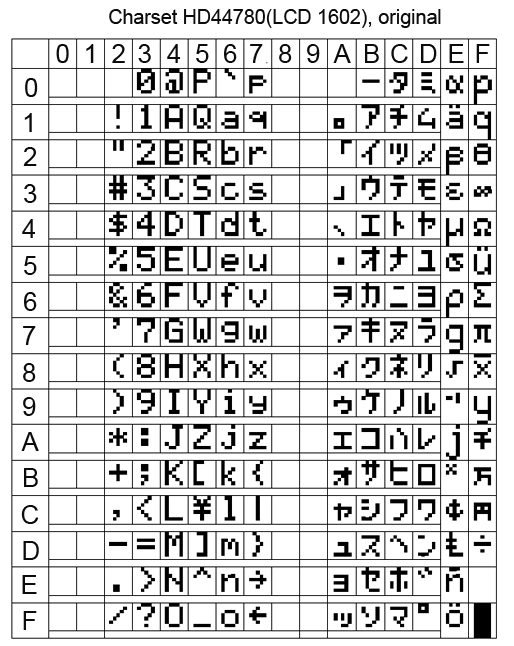

In principle, there is nothing terrible if you write Russian words in LCD in English letters. Vaughn, even the venerable French company Shneider Electric (the same one that sold howitzers to the king before the revolution) for a decade and a half did not allow herself to introduce Russian into their famous Zelio programmable relays. But this does not prevent them from actively trading in the entire CIS. Moreover, the channels, Spanish and Portuguese have entered.
At many of our factories, these Zelio communicate with staff with phrases like “NASOS 1 VKL”.
When it is not clear whether there are Russian letters in a particular LCD, you need to display all the characters of its character generator. If there is a Cyrillic alphabet, it starts with the 160 position.
Sketch 4, display all characters from the character generator LCD 1602 table
/*Последовательно выводит на LCD все символы его знакогенератора
 * LCD подключен по шине i2c
 */#include<LiquidCrystal_I2C.h>LiquidCrystal_I2C lcd(0x27,16,2);  // Устанавливаем дисплейvoidsetup(){
  // put your setup code here, to run once:
  lcd.init();
  lcd.clear();
}
voidloop(){
int i,y;
while(1)
{
  for (i=0; i < 16; i++)
  {
      lcd.clear();
      lcd.setCursor(0,0);
      lcd.print(String(i*16)+" - "+String(i*16+15));
      lcd.setCursor(0,1);
      for(y=0;y<16;y++)
       lcd.print(char(i*16+y));
      delay(3000);
   }
}
}
But even if your LCD 1602 is Russified, displaying Russian words is not so easy. At least using the “LiquidCrystal_I2C.h” library when working with LCDs on the i2c bus.
If you simply display the Russian text, for example, the lcd.print instruction (“Hello !!!”), then instead of “Hello !!!” some kind of rubbish will appear on the screen.
This is because the Russian letters Arduino IDE translates into double-byte UTF-8 code, and in the LCD all single-byte characters.
The same problem, by the way, is observed when transferring Russian texts from Arduino to the monitor of the Arduino IDE port. Arduino transmits Russian letters in a two-byte UTF-8 encoding to the serial port, and the Arduino IDE port monitor tries to read them in the single-byte Windows-1251 encoding (cp1251). Although cp1251 is also 8-bit, as is the LCD 1602 encoding, but it does not match it.
You can create Russian texts through character codes. For example, the line "LCD display" on the Russified LCD will be displayed as follows:
lcd.print("\243K \343\270c\276\273e\271");But I do not like this approach.
In order to correctly display the Russian text on the Russified LCD 1602, several libraries were invented for Arduino. But after reading the reviews, I saw that many complain about glitches when using them.
Therefore, in my multi-level menu program I myself wrote a simple function to transform UTF-8 into LCD codes. True, he did it only for the capital Russian letters, which suits me perfectly.
The function of converting capital Russian letters UTF-8 into single-byte code LCD 1602
/*
 *  Перекодировка UTF-8 русских букв (только заглавных) в коды LCD
 * а то Ардуино выводит их неправильно
 */byte  MasRus[33][2]= {
                      144,  0x41,   //А145,  0xa0,
                      146,  0x42,
                      147,  0xa1,
                      148,  0xe0,
                      149,  0x45,
                      129,  0xa2,
                      150,  0xa3,
                      151,  0xa4,
                      152,  0xa5,
                      153,  0xa6,
                      154,  0x4b,
                      155,  0xa7,
                      156,  0x4d,
                      157,  0x48,
                      158,  0x4f,
                      159,  0xa8,
                      160,  0x50,
                      161,  0x43,
                      162,  0x54,
                      163,  0xa9,
                      164,  0xaa,
                      165,  0x58,
                      166,  0xe1,
                      167,  0xab,
                      168,  0xac,
                      169,  0xe2,
                      170,  0xad,
                      171,  0xae,
                      172,  0xc4,
                      173,  0xaf,
                      174,  0xb0,
                      175,  0xb1//Я
  };
String RusStrLCD(String StrIn)
{
  String StrOut="";
  byte b1;
  byte y;
  byte l=StrIn.length();
  for(byte i=0; i<l; i++)
   {
    b1=StrIn.charAt(i);
    if (b1<128)
     StrOut=StrOut+char(b1);
    else
    {
      if (b1==208)      //байт==208, это первый байт из 2-байтного кода рус. буквы
      {
        b1=StrIn.charAt(i+1);
        for(y=0; y<33; y++)
         if(MasRus[y][0]==b1)
          {
            StrOut=StrOut+char(MasRus[y][1]);
            break;
          }
        }
       i++;
     }
   }
  return StrOut;
}
On this about homemade HMI with i2c bus, I have everything.
Oh yeah, at the beginning of the article I wrote that I was doing HMI not entirely for Arduino, but for arduino-compatible equipment. This is me about the CONTROLLINO MAXI PLC , which is programmed from the Arduino IDE (and many others).
CONTROLLINO MAXI is actually an Arduino + a bunch of shields and everything is designed as an industrial PLC. But about him next time.
Links
→ Archive with layouts, sketches and a printed circuit board in lay6 format
→ Arduino-compatible СONTROLLINO PLC , the work with which inspired the creation of HMI i2c
→ PCF8574 port extender and its connection to Arduino
→ FC-113 boardto operate LCD 1602 via i2c bus and connect it to Arduino
→ Multi-level tree menu , general principles of C creation
→ UTF-8 encoding
→ Windows-1251 encoding