GFDM - how to use radio resources even more efficiently
New technologies are bursting into our lives every year. Not long ago we used GSM, and now the fifth generation of communication standards is knocking on our gates, increasing the data transfer rate, reducing the signal transmission delay, using MIMO to its fullest coil and scanning the spectrum in the area of operating frequencies. And today I want to tell you how modulation was changed in the fifth generation of the communication standard, how GFDM was used instead of OFDM and what is the difference between them.
To begin, let me tell you a little about OFDM or orthogonal frequency division of channels that was used in 4G.
In data transmission systems, there are three types of channel separation: time, frequency and code. OFDM is a representative of frequency division channels. Frequency division of channels implies the following scheme of operation: the transmitter divides the data stream into N parallel streams and each stream transmits at some fixed frequency (subcarrier). It is known that the subcarriers themselves are orthogonal to each other, i.e. subcarrier number 1 can not affect the subcarrier number 2. However, we transmit symbols for each subcarrier and each symbol occupies its own frequency band. Let's look at the spectrum of the symbol and the transmitted signal.
As can be seen, the spectrum of the symbol moves to the subcarrier frequency over which it is transmitted. Here we come to the fundamental problem. If the symbol is finite in time, it occupies an infinite region of the spectrum. This means that the data in subcarrier # 1 and # 2 will now overlap and interfere with each other. It is meaningless to transmit one symbol for an infinitely long time, because we need to get information as quickly as possible, which means we will not be able to avoid mutual influence between subcarriers. However, we can minimize it using different techniques.
OFDM uses one of these techniques. Let's take a closer look at the spectrum above. The spectrum on each subcarrier takes a zero value with a certain periodicity; moreover, the frequency depends on the symbol duration.
Then, by setting a fixed symbol duration, we can choose subcarriers so that for subcarrier No. 2 the signal overlap from subcarrier No. 1 and No. 3 is minimal. The inter-channel influence will also be minimal. A typical spectrum of subcarrier data in OFDM is shown below. As you can see the zero value of the spectrum of each subcarrier falls to the point where the values of the subcarriers are maximum.
The solution is really good and interesting, but unfortunately there is always a "but". And here the first "but" - multipath signal propagation. More precisely the price of eliminating its influence. OFDM allows you to reduce intersymbol interference by using a cyclic prefix and the duration of the cyclic prefix increases with increasing number of multipath components. Cyclic prefixes are located between all characters in the time domain. This means that, for example, for 1 second of the total operating time of the system you will transmit information within 0.5 seconds, and 0.5 seconds will be taken by cyclic prefixes. Agree ineffectively? I want to use the radio resources to the maximum.

The second disadvantage is out-of-band emission. This is when your system gets a little beyond the allowed frequency range. As I wrote earlier, this cannot be avoided. However, the smaller the value of out-of-band emissions, the closer in frequency two different systems will be located and the radio resource will be used more effectively. With the increase in the value of radio resources, this becomes critical.
The third drawback comes from the noise-like signal. Remember, our signal is evenly distributed across the spectrum, with each subcarrier taking random phase values with equal probability. In some approximation, the probability density will be similar to the normal one, like in the Gaussian distribution. Well, what's wrong, you say, because now our signal can not be distinguished from noise. Not so simple. As we remember, the probability density of the Gaussian noise lies from minus infinity to plus infinity. In a real output signal, this leads to an increase in the PAPR or the ratio of the maximum signal amplitude to the average. This increases the cost of the output stages of the amplifier and distorts the real output signal. Below is an example of an OFDM signal with an oversized block size for statistics. The left image shows the initial phases at each of the frequencies. Phases show that QPSK modulation is used. Data was generated equally likely. In the image in the center, we can say that the powers of the subcarriers are equal to each other. The right graph shows that the probability density of the data at the transmitter output tends to normal, and the dynamic range is 100 dB. This is a large enough value that can affect the price of equipment.

GFDM is in the fifth generation of the standard and is trying to solve these problems. In addition, GFDM allows you to selectively use subcarriers if they are already occupied by another system. GFDM is also based on the concept of subcarriers, with a few additions. To increase the efficiency of using radio resources, data is transmitted in blocks both in frequency (as in OFDM) and in time. Accordingly, the guard interval is located at the end of each block, eliminating interference between the blocks, but not between the symbols in the block.

Here lies the main difference GFDM. To eliminate intersymbol interference in the block, pulse shaping filters are used. Each character in the time domain is now represented as a given function. This function occupies the entire data block in time, however, it minimizes both inter-channel and intersymbol interference.
Three types of filters are mainly used: “sinc”, “raised cosine” and “root-raised cosine” filters. The sinc filter uses the sinx / x function as the basis for the symbol. As it turned out, if you set the sinc function as a symbol, its mapping to the frequency domain will be as close as possible to the rectangle, and thus minimizes inter-channel interference. In this case, in the time domain, the characters will not affect each other at the time of sampling.
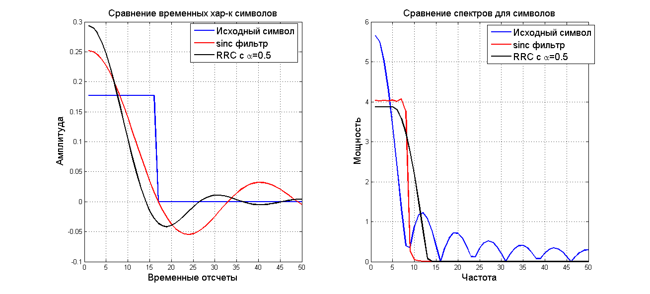
However, this is not effective enough and “root-raised cosine” filters were used. These are filters similar to pulse shaping, but intentionally introducing intersymbol interference and regulating its level. Root-raised cosine filters have one variable called alpha which controls the level of intersymbol interference. Below are presented for comparison the patterns of the source symbols (impulse responses), “pulse shaping” and “root-raised cosine” with their mapping to the frequency domain.
At first glance, the “root-raised cosine” filter is worse than the “pulse shaping”, but on the logarithmic scale, the decay rate is higher than that of the “root-raised cosine” filter. And the key value of -60 dB is reached faster by the “root-raised cosine” filter.
However, nothing comes for nothing. It is noticeable that the “root-raised cosine” filter has great power near the cut-off frequency and this affects the number of errors during system operation. Below is the dependence of the number of errors on the value of the alpha parameter for a receiver based on an OLS or pseudo-inverse matrix. With increasing alpha, the number of errors increases, and therefore the quality of communication decreases. To reduce this effect, interference suppression methods have been developed, for example, Double side interference cancellation, which reduce the number of errors to almost the level of OFDM.

Look at the frequency characteristics below, namely the level of out-of-band emissions. As you can see, GFDM reduces the out-of-band emissions to -60 dB faster, which means that radio resources with it are used more efficiently. Moreover, the operator has a choice between efficiency in radio resources and the number of errors. This trade-off will have a different solution for each operator.

Today I think there is enough information for you. Next time I will talk about how I used tensors in my master’s thesis to describe GFDM modulation, described the modulation matrix through one of the tensor operations and about my channel estimation method through known symbols in the data block. In addition, I’m probably talking about an interesting PAPR reduction technique currently in use.
Abbreviations
OFDM Ортогональное частотное разделение каналов
GFDM Обобщенное частотное разделение каналов
PAPR Peek-to-Average Power Ratio
Pulse shaping filter — фильтр формирования импульсов
Raised cosine filter — Фильтр с характеристикой: Приподнятый косинус
Root-raised cosine filter — Фильтр с характеристикой: Корень из приподнятого косинуса
GFDM Обобщенное частотное разделение каналов
PAPR Peek-to-Average Power Ratio
Pulse shaping filter — фильтр формирования импульсов
Raised cosine filter — Фильтр с характеристикой: Приподнятый косинус
Root-raised cosine filter — Фильтр с характеристикой: Корень из приподнятого косинуса
OFDM Introduction
How does it work
To begin, let me tell you a little about OFDM or orthogonal frequency division of channels that was used in 4G.
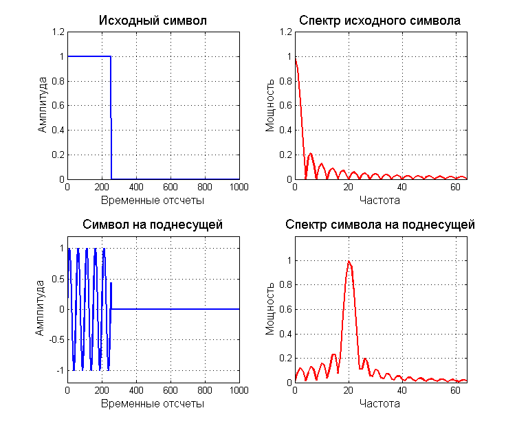
In data transmission systems, there are three types of channel separation: time, frequency and code. OFDM is a representative of frequency division channels. Frequency division of channels implies the following scheme of operation: the transmitter divides the data stream into N parallel streams and each stream transmits at some fixed frequency (subcarrier). It is known that the subcarriers themselves are orthogonal to each other, i.e. subcarrier number 1 can not affect the subcarrier number 2. However, we transmit symbols for each subcarrier and each symbol occupies its own frequency band. Let's look at the spectrum of the symbol and the transmitted signal.
As can be seen, the spectrum of the symbol moves to the subcarrier frequency over which it is transmitted. Here we come to the fundamental problem. If the symbol is finite in time, it occupies an infinite region of the spectrum. This means that the data in subcarrier # 1 and # 2 will now overlap and interfere with each other. It is meaningless to transmit one symbol for an infinitely long time, because we need to get information as quickly as possible, which means we will not be able to avoid mutual influence between subcarriers. However, we can minimize it using different techniques.
OFDM uses one of these techniques. Let's take a closer look at the spectrum above. The spectrum on each subcarrier takes a zero value with a certain periodicity; moreover, the frequency depends on the symbol duration.
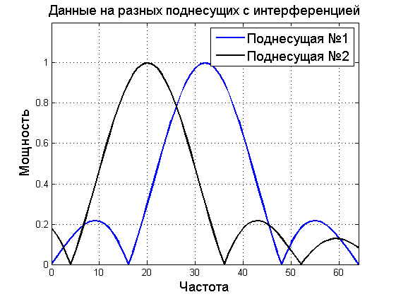
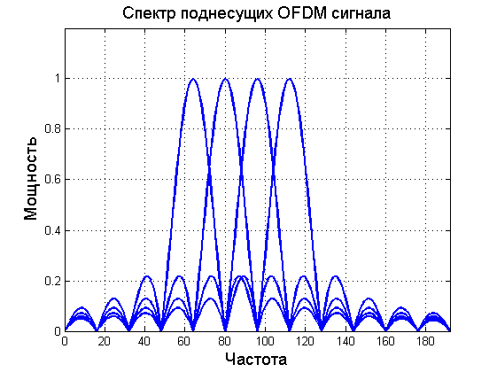
Then, by setting a fixed symbol duration, we can choose subcarriers so that for subcarrier No. 2 the signal overlap from subcarrier No. 1 and No. 3 is minimal. The inter-channel influence will also be minimal. A typical spectrum of subcarrier data in OFDM is shown below. As you can see the zero value of the spectrum of each subcarrier falls to the point where the values of the subcarriers are maximum.
disadvantages
The solution is really good and interesting, but unfortunately there is always a "but". And here the first "but" - multipath signal propagation. More precisely the price of eliminating its influence. OFDM allows you to reduce intersymbol interference by using a cyclic prefix and the duration of the cyclic prefix increases with increasing number of multipath components. Cyclic prefixes are located between all characters in the time domain. This means that, for example, for 1 second of the total operating time of the system you will transmit information within 0.5 seconds, and 0.5 seconds will be taken by cyclic prefixes. Agree ineffectively? I want to use the radio resources to the maximum.
The second disadvantage is out-of-band emission. This is when your system gets a little beyond the allowed frequency range. As I wrote earlier, this cannot be avoided. However, the smaller the value of out-of-band emissions, the closer in frequency two different systems will be located and the radio resource will be used more effectively. With the increase in the value of radio resources, this becomes critical.
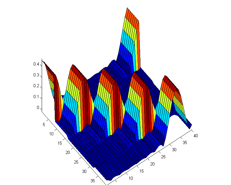
The third drawback comes from the noise-like signal. Remember, our signal is evenly distributed across the spectrum, with each subcarrier taking random phase values with equal probability. In some approximation, the probability density will be similar to the normal one, like in the Gaussian distribution. Well, what's wrong, you say, because now our signal can not be distinguished from noise. Not so simple. As we remember, the probability density of the Gaussian noise lies from minus infinity to plus infinity. In a real output signal, this leads to an increase in the PAPR or the ratio of the maximum signal amplitude to the average. This increases the cost of the output stages of the amplifier and distorts the real output signal. Below is an example of an OFDM signal with an oversized block size for statistics. The left image shows the initial phases at each of the frequencies. Phases show that QPSK modulation is used. Data was generated equally likely. In the image in the center, we can say that the powers of the subcarriers are equal to each other. The right graph shows that the probability density of the data at the transmitter output tends to normal, and the dynamic range is 100 dB. This is a large enough value that can affect the price of equipment.
GFDM and its technology
GFDM is in the fifth generation of the standard and is trying to solve these problems. In addition, GFDM allows you to selectively use subcarriers if they are already occupied by another system. GFDM is also based on the concept of subcarriers, with a few additions. To increase the efficiency of using radio resources, data is transmitted in blocks both in frequency (as in OFDM) and in time. Accordingly, the guard interval is located at the end of each block, eliminating interference between the blocks, but not between the symbols in the block.
Here lies the main difference GFDM. To eliminate intersymbol interference in the block, pulse shaping filters are used. Each character in the time domain is now represented as a given function. This function occupies the entire data block in time, however, it minimizes both inter-channel and intersymbol interference.
Three types of filters are mainly used: “sinc”, “raised cosine” and “root-raised cosine” filters. The sinc filter uses the sinx / x function as the basis for the symbol. As it turned out, if you set the sinc function as a symbol, its mapping to the frequency domain will be as close as possible to the rectangle, and thus minimizes inter-channel interference. In this case, in the time domain, the characters will not affect each other at the time of sampling.
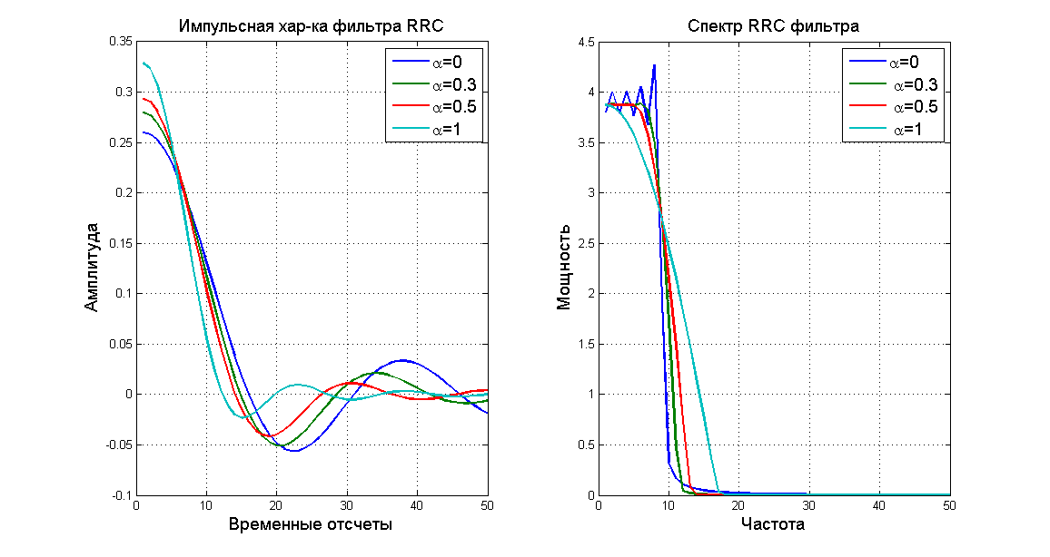
However, this is not effective enough and “root-raised cosine” filters were used. These are filters similar to pulse shaping, but intentionally introducing intersymbol interference and regulating its level. Root-raised cosine filters have one variable called alpha which controls the level of intersymbol interference. Below are presented for comparison the patterns of the source symbols (impulse responses), “pulse shaping” and “root-raised cosine” with their mapping to the frequency domain.
At first glance, the “root-raised cosine” filter is worse than the “pulse shaping”, but on the logarithmic scale, the decay rate is higher than that of the “root-raised cosine” filter. And the key value of -60 dB is reached faster by the “root-raised cosine” filter.
However, nothing comes for nothing. It is noticeable that the “root-raised cosine” filter has great power near the cut-off frequency and this affects the number of errors during system operation. Below is the dependence of the number of errors on the value of the alpha parameter for a receiver based on an OLS or pseudo-inverse matrix. With increasing alpha, the number of errors increases, and therefore the quality of communication decreases. To reduce this effect, interference suppression methods have been developed, for example, Double side interference cancellation, which reduce the number of errors to almost the level of OFDM.
update
прошу прощения за английский заголовок рисунка
Look at the frequency characteristics below, namely the level of out-of-band emissions. As you can see, GFDM reduces the out-of-band emissions to -60 dB faster, which means that radio resources with it are used more efficiently. Moreover, the operator has a choice between efficiency in radio resources and the number of errors. This trade-off will have a different solution for each operator.
Today I think there is enough information for you. Next time I will talk about how I used tensors in my master’s thesis to describe GFDM modulation, described the modulation matrix through one of the tensor operations and about my channel estimation method through known symbols in the data block. In addition, I’m probably talking about an interesting PAPR reduction technique currently in use.
Reference
M. Matthe, N. Michailow, and I.Gaspar, \Gfdm for 5g cellular networks," IEEE transactions on commenications vol 62, 2014.
M. Matthe, N. Michailow, and G. Fettweis, \Influense of pulse shaping on bit-error rate
performance and out of band radiation of gfdm," ICC 14 WS 5G, 2014.
G. Fettweis, M. Krondorf, and S. Bittner, \Gfdm — generalized frequency division multiplexing," Vehicular Technology Conference, 2009. VTC Spring 2009. IEEE 69th, 2009.
B. M. Alves, L. Mendes, D.A.Guimaraes, and I. Gaspar, \Performance gfdm over frequency selective channels," Revista Telecemunicationes vol 15, Dec 2013.