Tower Steam Engine
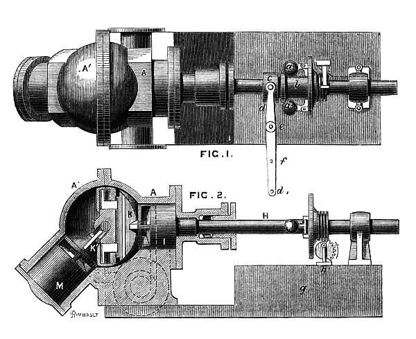
Instead of the usual cylinder in this steam engine, there was a sphere. Hollow sphere, within which everything happened.
In the sphere, a disk rotated and oscillated, on each side of which the quarters of the ball “threw” back and forth. As you can see, in words it is impossible to explain, therefore the gif: a
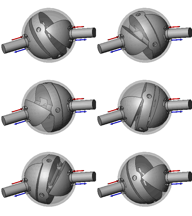
little slower, the gif The
red arrows are the supply of fresh steam, the blue ones are the release of waste.
The shafts were placed at an angle of 135 degrees to each other. The steam through the hole in the quarter came under the plane pressed to the disk, expanded (doing useful work) and after turning the quarter left through the same hole. Quarters, therefore, functioned as steam supply / removal valves. The dangling disc did what a piston does in a conventional steam engine. A crank mechanism was not at all, because it was not necessary to convert the reciprocating motion into rotational.
Main node:
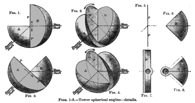
So far, on one side of the quarter there was a working stroke (expansion of steam), on the other side of it there was an idling (release of exhaust steam). On the other side of the disc, the same thing happened with a phase shift of 90 degrees. Due to the relative position of the quarters, the disk was given rotation and vibrations.
In fact, it was a cardan transmission with an internal source of energy. The green disk-crosspiece of the cardan gear makes the same rotational-oscillatory movements: The
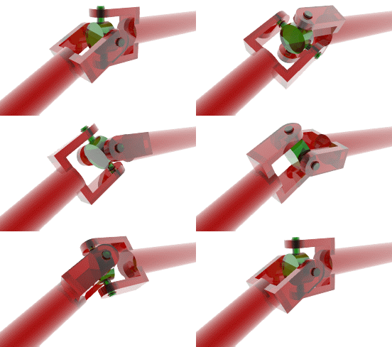
rotation was transmitted to two shafts coming out of the motor. It was possible to remove energy from both, but in practice, judging by the figures, they used one for the drive.
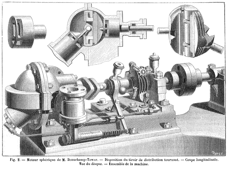
As the French magazine La Nature of 1884 noted, the spherical engine allowed higher rotational speeds compared to the piston counterparts and, therefore, it was well suited as a drive for an electric generator.
The engine had low levels of noise and vibration and was very compact. A motor with an internal ball diameter of 10 cm and a rotational speed of 500 rpm at a vapor pressure of 3 atm produced 1 horsepower, at 8.5 atm - 2.5 hp. The largest model with a diameter of 63 cm had a capacity of 624 "horses."
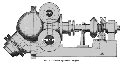
But. The spherical motor was difficult to manufacture and required a lot of steam. It was produced and for some time actually operated as a drive for generators in the British fleet and on the railways of the Great Eastern Railway (installed on a steam boiler and served for electric lighting of cars). However, because of these shortcomings did not catch on.
PS It should be noted that the inventor of the sphericalhorse of the engine Beauchamp Tower (Beauchamp Tower) has not disappeared for engineering.
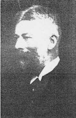
Apparently, he was the first to observe the “oil wedge” in the sliding bearings and measure the pressure in it. Those. modern engineering has been using Mr. Tower’s research so far.
Drawn here and there .

In the sphere, a disk rotated and oscillated, on each side of which the quarters of the ball “threw” back and forth. As you can see, in words it is impossible to explain, therefore the gif: a

little slower, the gif The
red arrows are the supply of fresh steam, the blue ones are the release of waste.
The shafts were placed at an angle of 135 degrees to each other. The steam through the hole in the quarter came under the plane pressed to the disk, expanded (doing useful work) and after turning the quarter left through the same hole. Quarters, therefore, functioned as steam supply / removal valves. The dangling disc did what a piston does in a conventional steam engine. A crank mechanism was not at all, because it was not necessary to convert the reciprocating motion into rotational.
Main node:

So far, on one side of the quarter there was a working stroke (expansion of steam), on the other side of it there was an idling (release of exhaust steam). On the other side of the disc, the same thing happened with a phase shift of 90 degrees. Due to the relative position of the quarters, the disk was given rotation and vibrations.
In fact, it was a cardan transmission with an internal source of energy. The green disk-crosspiece of the cardan gear makes the same rotational-oscillatory movements: The

rotation was transmitted to two shafts coming out of the motor. It was possible to remove energy from both, but in practice, judging by the figures, they used one for the drive.

As the French magazine La Nature of 1884 noted, the spherical engine allowed higher rotational speeds compared to the piston counterparts and, therefore, it was well suited as a drive for an electric generator.
The engine had low levels of noise and vibration and was very compact. A motor with an internal ball diameter of 10 cm and a rotational speed of 500 rpm at a vapor pressure of 3 atm produced 1 horsepower, at 8.5 atm - 2.5 hp. The largest model with a diameter of 63 cm had a capacity of 624 "horses."

But. The spherical motor was difficult to manufacture and required a lot of steam. It was produced and for some time actually operated as a drive for generators in the British fleet and on the railways of the Great Eastern Railway (installed on a steam boiler and served for electric lighting of cars). However, because of these shortcomings did not catch on.
PS It should be noted that the inventor of the spherical

Apparently, he was the first to observe the “oil wedge” in the sliding bearings and measure the pressure in it. Those. modern engineering has been using Mr. Tower’s research so far.
Drawn here and there .
