How GPUs handle branching
- Transfer
About article
This post is a short note designed for programmers who want to learn more about how the GPU handles branching. You can consider it an introduction to this topic. I recommend to start by looking at [ 1 ], [ 2 ] and [ 8 ] to get an idea of how the GPU execution model looks in general, because we will consider only one separate detail. For curious readers, there are all links at the end of the post. If you find errors, then contact me.
Content
- About article
- Content
- Vocabulary
- How is the GPU core different from the CPU core?
- What is consistency / discrepancy?
- Execution mask processing examples
- Fictional ISA
- AMD GCN ISA
- AVX512
- How to deal with the discrepancy?
- References
Vocabulary
- GPU - Graphics processing unit, GPU
- Flynn's classification
- SIMD - Single instruction multiple data, single instruction stream, multiple data stream
- SIMT - Single instruction multiple threads
- Wave (SIM) - a stream executed in the SIMD mode
- Line (lane) - a separate data stream in the SIMD model
- SMT - Simultaneous multi-threading, simultaneous multithreading (Intel Hyper-threading) [ 2 ]
- Multiple threads share core computing resources
- IMT - Interleaved multi-threading, alternating multithreading [ 2 ]
- Multiple threads use the kernel's shared computing resources, but only one is executed per clock.
- BB - Basic Block, a basic block - a linear sequence of instructions with a single jump at the end
- ILP - Instruction Level Parallelism, parallelism at the instruction level [ 3 ]
- ISA - Instruction Set Architecture, Command / Instruction Set Architecture
In my post, I will adhere to this invented classification. It roughly resembles how a modern GPU is organized.
Оборудование:

GPU -+

 |- ядро 0 -+

 | |- волна 0 +

 | | |- линия 0

 | | |- линия 1

 | | |- ...

 | | +- линия Q-1

 | |

 | |- ...

 | +- волна M-1

 |

 |- ...

 +- ядро N-1


* АЛУ - АЛУ SIMD


Программное обеспечение:

группа +

 |- поток 0

 |- ...

 +- поток N-1
Other names:
- The core may be called CU, SM, EU
- A wave can be called a wavefront, a hardware thread (HW thread), warp, a context
- A line can be called a program thread (SW thread)
How is the GPU core different from the CPU core?
Any current generation of GPU cores is less powerful than central processors: simple ILP / multi-issue [ 6 ] and prefetch [ 5 ], no forecasting or prediction of transitions / returns. All this, along with tiny caches, frees up a fairly large area on the chip, which is filled with many cores. Memory loading / storage mechanisms are able to cope with the channel width by an order of magnitude larger (this does not apply to integrated / mobile GPUs) than conventional CPUs, but you have to pay for this with high latencies. The GPU uses SMT to hide latency [ 2] - while one wave is idle, others use the free computing resources of the kernel. Usually the number of waves processed by one core depends on the registers used and is determined dynamically by allocating a fixed register file [ 8 ]. Planning for the execution of instructions is hybrid - dynamic-static [ 6 ] [ 11 4.4]. SMT kernels executed in SIMD mode achieve high FLOPS values (FLoating-point Operations Per Second, flops, number of floating point operations per second).
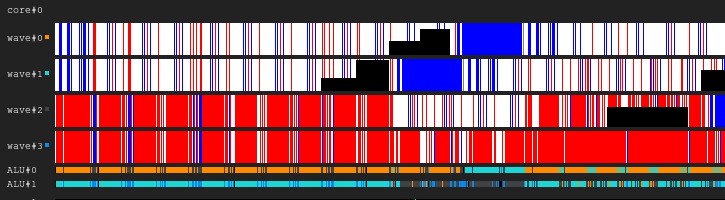
Legend chart. Black - inactive, white - active, gray - off, blue - idle, red - pending

Figure 1. Execution history 4: 2
The image shows the history of the execution mask, where the x-axis shows time running from left to right, and the y-axis represents the identifier of the line going from top to bottom. If you still do not understand this, then return to the drawing after reading the following sections.
This is an illustration of how the GPU core execution history may look like in a fictitious configuration: four waves share one sampler and two ALUs. The wave planner in each cycle issues two instructions from two waves. When a wave is idle when performing an access to memory or a long ALU operation, the scheduler switches to another pair of waves, due to which the ALU is constantly almost 100% occupied.
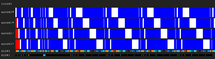
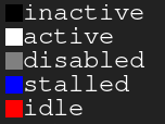
Figure 2. Execution history 4: 1
An example with the same load, but this time in each cycle of the instruction only one wave issues. Notice that the second ALU is starving.
Figure 3. Execution history 4: 4
This time, four instructions are issued in each cycle. Note that there are now too many requests to ALU, therefore two waves are almost constantly waiting (in fact, this is a mistake of the planning algorithm).
Update For more information on the difficulties of planning the implementation of instructions, see [ 12 ].
In the real world, GPUs have different core configurations: some can have up to 40 waves per core and 4 ALUs, others have 7 fixed waves and 2 ALUs. All this depends on many factors and is determined thanks to the painstaking process of architecture simulation.
In addition, real SIMD ALUs may have a narrower width than the waves they serve, and then it takes several cycles to process one issued instruction; the factor is called the length "chime" [ 3 ].
What is consistency / discrepancy?
Let's take a look at the following code snippet:
Example 1
uint lane_id = get_lane_id();
if (lane_id & 1) {
    // Do smth
}
// Do some more
Here we see a stream of instructions in which the execution path depends on the identifier of the line being executed. Obviously, different lines have different meanings. What is going to happen? There are different approaches to solving this problem [ 4], but ultimately they all do roughly the same thing. One such approach is the execution mask, which I will cover. This approach was used in the Nvidia GPUs before Volta and in the AMD GCN GPUs. The main point of the execution mask is that we store a bit for each line in the wave. If the corresponding line execution bit is 0, then no registers will be affected for the next instruction issued. In fact, the line should not feel the influence of the entire executed instruction, because its execution bit is 0. This works as follows: the wave travels along the control flow graph in the depth search order, saving the history of the selected transitions until the bits are set. I think it’s better to show it with an example.
Suppose we have waves with a width of 8. Here is what the execution mask for the code fragment looks like:
Example 1. History of the execution mask
                                  // execution mask
uint lane_id = get_lane_id();     // 11111111
if (lane_id & 1) {                // 11111111
    // Do smth                    // 01010101
}
// Do some more                   // 11111111
Now consider more complex examples:
Example 2
uint lane_id = get_lane_id();
for (uint i = lane_id; i < 16; i++) {
    // Do smth
}
Example 3
uint lane_id = get_lane_id();
if (lane_id < 16) {
    // Do smth
} else {
    // Do smth else
}
You may notice that history is necessary. When using the execution mask approach, equipment usually uses some kind of stack. The naive approach is to store a stack of tuples (exec_mask, address) and add convergence instructions that retrieve the mask from the stack and change the instruction pointer for the wave. In this case, the wave will have enough information to bypass the entire CFG for each line.
In terms of performance, it only takes a couple of loops to process a control flow instruction because of all this data storage. And don't forget that the stack has a limited depth.
Update. Thanks to @craigkolb I read the article [ 13], in which it is noted that the fork / join instructions of the AMD GCN first select a path from fewer threads [ 11 4.6], which guarantees that the depth of the mask stack is equal to log2.
Update. Obviously, it is almost always possible to embed everything in a shader / structure CFG in a shader, and therefore store the entire history of execution masks in registers and plan statically bypass / converge CFG [ 15 ]. After looking at the LLVM backend for AMDGPU, I did not find any evidence of processing stacks constantly issued by the compiler.
Runtime mask hardware support
Now take a look at these control flow graphs from Wikipedia:

Figure 4. Some of the types of control flow graphs.
What is the minimum set of mask control instructions that we need to handle all cases? Here's what it looks like in my artificial ISA with implicit parallelization, explicit mask control and fully dynamic synchronization of data conflicts:
push_mask BRANCH_END         ; Push current mask and reconvergence pointer
pop_mask                     ; Pop mask and jump to reconvergence instruction
mask_nz r0.x                 ; Set execution bit, pop mask if all bits are zero
; Branch instruction is more complicated
; Push current mask for reconvergence
; Push mask for (r0.x == 0) for else block, if any lane takes the path
; Set mask with (r0.x != 0), fallback to else in case no bit is 1
br_push r0.x, ELSE, CONVERGE
Let's take a look at case d).
A:
    br_push r0.x, C, D
B:
C:
    mask_nz r0.y
    jmp B
D:
    ret
I am not a specialist in the analysis of control flows or the design of ISA, so I am sure that there is a case that my artificial ISA will not be able to handle, but this is not important, because a structured CFG should be enough for everyone.
Update. Read more about GCN support for control flow instructions here: [ 11 ] ch.4, and on LLVM implementation here: [ 15 ].
Conclusion:
- Divergence - the resulting difference in the paths chosen by different lines of the same wave
- Consistency - no discrepancy.
Execution mask processing examples
Fictional ISA
I compiled the previous code snippets in my artificial ISA and ran them on a simulator in SIMD32. See how it handles the execution mask.
Update. Note that an artificial simulator always chooses the true path, and this is not the best way.
Example 1
; uint lane_id = get_lane_id();
    mov r0.x, lane_id
; if (lane_id & 1) {
    push_mask BRANCH_END
    and r0.y, r0.x, u(1)
    mask_nz r0.y
LOOP_BEGIN:
    ; // Do smth
    pop_mask                ; pop mask and reconverge
BRANCH_END:
    ; // Do some more
    ret
Figure 5. Execution history of example 1
Have you noticed a black area? This time wasted. Some lines wait for others to complete the iteration.
Example 2
; uint lane_id = get_lane_id();
    mov r0.x, lane_id
; for (uint i = lane_id; i < 16; i++) {
    push_mask LOOP_END        ; Push the current mask and the pointer to reconvergence instruction
LOOP_PROLOG:
    lt.u32 r0.y, r0.x, u(16)  ; r0.y <- r0.x < 16
    add.u32 r0.x, r0.x, u(1)  ; r0.x <- r0.x + 1
    mask_nz r0.y              ; exec bit <- r0.y != 0 - when all bits are zero next mask is popped
LOOP_BEGIN:
    ; // Do smth
    jmp LOOP_PROLOG
LOOP_END:
    ; // }
    ret
Figure 6. History of example 2
Example 3
    mov r0.x, lane_id
    lt.u32 r0.y, r0.x, u(16)
    ; if (lane_id < 16) {
        ; Push (current mask, CONVERGE) and (else mask, ELSE)
        ; Also set current execution bit to r0.y != 0
    br_push r0.y, ELSE, CONVERGE
THEN:
    ; // Do smth
    pop_mask
    ; } else {
ELSE:
    ; // Do smth else
    pop_mask
    ; }
CONVERGE:
    ret
Figure 7. Execution history of example 3
AMD GCN ISA
Update. GCN also uses explicit mask processing, more about this can be found here: [ 11 4.x]. I decided to show some examples from their ISA, thanks to the shader-playground this is easy to do. Perhaps someday I will find a simulator and manage to get diagrams.
Note that the compiler is smart, so you can get other results. I tried to trick the compiler so that it wouldn’t optimize my branches by putting there pointer loops and then cleaning up the assembler code; I'm not a GCN specialist, so a few important ones
nopmight be skipped.Also note that the S_CBRANCH_I / G_FORK and S_CBRANCH_JOIN instructions are not used in these fragments because they are simple and the compiler does not support them. Therefore, unfortunately, it was not possible to consider the stack of masks. If you know how to make the compiler issue stack processing, please tell me.
Update. See this report @ SiNGUL4RiTY on the implementation of vectorized control flow in LLVM-backend using AMD.
Example 1
; uint lane_id = get_lane_id();
; GCN uses 64 wave width, so lane_id = thread_id & 63
; There are scalar s* and vector v* registers
; Executon mask does not affect scalar or branch instructions
    v_mov_b32     v1, 0x00000400      ; 1024 - group size
    v_mad_u32_u24  v0, s12, v1, v0    ; thread_id calculation
    v_and_b32     v1, 63, v0
; if (lane_id & 1) {
    v_and_b32     v2, 1, v0
    s_mov_b64     s[0:1], exec        ; Save the execution mask
    v_cmpx_ne_u32  exec, v2, 0        ; Set the execution bit
    s_cbranch_execz  ELSE             ; Jmp if all exec bits are zero
; // Do smth
ELSE:
; }
; // Do some more
    s_mov_b64     exec, s[0:1]        ; Restore the execution mask
    s_endpgm
Example 2
; uint lane_id = get_lane_id();
    v_mov_b32     v1, 0x00000400
    v_mad_u32_u24  v0, s8, v1, v0     ; Not sure why s8 this time and not s12
    v_and_b32     v1, 63, v0
; LOOP PROLOG
    s_mov_b64     s[0:1], exec        ; Save the execution mask
    v_mov_b32     v2, v1
    v_cmp_le_u32  vcc, 16, v1
    s_andn2_b64   exec, exec, vcc     ; Set the execution bit
    s_cbranch_execz  LOOP_END         ; Jmp if all exec bits are zero
; for (uint i = lane_id; i < 16; i++) {
LOOP_BEGIN:
    ; // Do smth
    v_add_u32     v2, 1, v2
    v_cmp_le_u32  vcc, 16, v2
    s_andn2_b64   exec, exec, vcc     ; Mask out lanes which are beyond loop limit
    s_cbranch_execnz  LOOP_BEGIN      ; Jmp if non zero exec mask
LOOP_END:
    ; // }
    s_mov_b64     exec, s[0:1]        ; Restore the execution mask
    s_endpgm
Example 3
; uint lane_id = get_lane_id();
    v_mov_b32     v1, 0x00000400
    v_mad_u32_u24  v0, s12, v1, v0
    v_and_b32     v1, 63, v0
    v_and_b32     v2, 1, v0
    s_mov_b64     s[0:1], exec        ; Save the execution mask
; if (lane_id < 16) {
    v_cmpx_lt_u32  exec, v1, 16       ; Set the execution bit
    s_cbranch_execz  ELSE             ; Jmp if all exec bits are zero
; // Do smth
; } else {
ELSE:
    s_andn2_b64   exec, s[0:1], exec  ; Inverse the mask and & with previous
    s_cbranch_execz  CONVERGE         ; Jmp if all exec bits are zero
; // Do smth else
; }
CONVERGE:
    s_mov_b64     exec, s[0:1]        ; Restore the execution mask
; // Do some more
    s_endpgm
AVX512
Update. @tom_forsyth pointed out to me that the AVX512 extension also has explicit mask processing, so here are some examples. More details about this can be found in [ 14 ], 15.x and 15.6.1. It's not exactly a GPU, but it still has a real SIMD16 with 32 bits. Code snippets were created using ISPC (–target = avx512knl-i32x16) godbolt and were heavily redesigned, so they may not be 100% true.
Example 1
    ; Imagine zmm0 contains 16 lane_ids
    ; AVXZ512 comes with k0-k7 mask registers
    ; Usage:
    ; op reg1 {k[7:0]}, reg2, reg3
    ; k0 can not be used as a predicate operand, only k1-k7
; if (lane_id & 1) {
    vpslld       zmm0 {k1}, zmm0, 31  ; zmm0[i] = zmm0[i] << 31
    kmovw        eax, k1              ; Save the execution mask
    vptestmd     k1 {k1}, zmm0, zmm0  ; k1[i] = zmm0[i] != 0
    kortestw     k1, k1
    je           ELSE                 ; Jmp if all exec bits are zero
; // Do smth
    ; Now k1 contains the execution mask
    ; We can use it like this:
    ; vmovdqa32 zmm1 {k1}, zmm0
ELSE:
; }
    kmovw        k1, eax              ; Restore the execution mask
; // Do some more
    ret
Example 2
 ; Imagine zmm0 contains 16 lane_ids
    kmovw         eax, k1               ; Save the execution mask
    vpcmpltud     k1 {k1}, zmm0, 16     ; k1[i] = zmm0[i] < 16
    kortestw      k1, k1
    je            LOOP_END              ; Jmp if all exec bits are zero
    vpternlogd    zmm1 {k1}, zmm1, zmm1, 255   ; zmm1[i] = -1
; for (uint i = lane_id; i < 16; i++) {
LOOP_BEGIN:
; // Do smth
    vpsubd        zmm0 {k1}, zmm0, zmm1 ; zmm0[i] = zmm0[i] + 1
    vpcmpltud     k1 {k1}, zmm0, 16     ; masked k1[i] = zmm0[i] < 16
    kortestw      k1, k1
    jne           LOOP_BEGIN            ; Break if all exec bits are zero
LOOP_END:
; // }
    kmovw        k1, eax                ; Restore the execution mask
; // Do some more
    ret
Example 3
 ; Imagine zmm0 contains 16 lane_ids
; if (lane_id & 1) {
    vpslld       zmm0 {k1}, zmm0, 31  ; zmm0[i] = zmm0[i] << 31
    kmovw        eax, k1              ; Save the execution mask
    vptestmd     k1 {k1}, zmm0, zmm0  ; k1[i] = zmm0[i] != 0
    kortestw     k1, k1
    je           ELSE                 ; Jmp if all exec bits are zero
THEN:
; // Do smth
; } else {
ELSE:
    kmovw        ebx, k1
    andn         ebx, eax, ebx
    kmovw        k1, ebx              ; mask = ~mask & old_mask
    kortestw     k1, k1
    je           CONVERGE             ; Jmp if all exec bits are zero
; // Do smth else
; }
CONVERGE:
kmovw            k1, eax              ; Restore the execution mask
; // Do some more
    ret
How to deal with the discrepancy?
I tried to create a simple but complete illustration of how inefficiency arises from combining diverging lines.
Imagine a simple piece of code:
uint thread_id = get_thread_id();
uint iter_count = memory[thread_id];
for (uint i = 0; i < iter_count; i++) {
    // Do smth
}
Let's create 256 threads and measure their execution time:
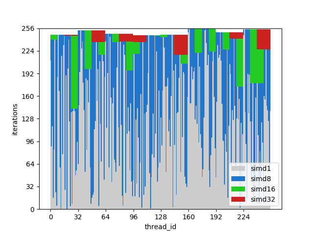
Figure 8. Runtime of divergent threads.
The x axis is the identifier of the program stream, the y axis is the clock cycles; different columns show how much time is wasted when grouping flows with different wavelengths compared to single-threaded execution.
The wave run time is equal to the maximum run time among the lines contained in it. You can see that performance drops dramatically already with SIMD8, and further expansion just makes it a little worse.
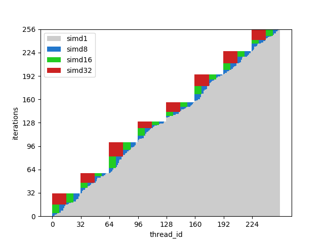
Figure 9. Matching threads execution time The
same columns are shown in this figure, but this time the number of iterations is sorted by thread IDs, that is, threads with a similar number of iterations are transmitted to a single wave.
For this example, execution is potentially accelerated by about half.
Of course, the example is too simple, but I hope you understand the point: the discrepancy at execution stems from the discrepancy of the data, so CFGs must be simple and the data consistent.
For example, if you are writing a ray tracer, you might benefit from grouping the rays with the same direction and position, because they will most likely go through the same nodes in the BVH. See [ 10 ] and other related articles for more details .
It is also worth mentioning that there are techniques for dealing with discrepancies at the hardware level, for example, Dynamic Warp Formation [ 7 ] and predicted execution for small branches.
References
[1] A trip through the Graphics Pipeline
[2] Kayvon Fatahalian: PARALLEL COMPUTING
[3] Computer Architecture A Quantitative Approach
[4] Stack-less SIMT reconvergence at low cost
[5] Dissecting GPU memory hierarchy through microbenchmarking
[6] Dissecting the NVIDIA Volta GPU Architecture via Microbenchmarking
[7] Dynamic Warp Formation and Scheduling for Efficient GPU Control Flow
[8] Maurizio Cerrato: GPU Architectures
[9] Toy GPU simulator
[10] Reducing Branch Divergence in GPU Programs
[11] “Vega” Instruction Set Architecture
[12]Joshua Barczak: Simulating Shader Execution for GCN
[13] Tangent Vector: A Digression on Divergence
[14] Intel 64 and IA-32 Architectures Software Developer's Manual
[15] Vectorizing Divergent Control-Flow for SIMD Applications