Signs from Above: How We Saved Cartographers from Unnecessary Work and Red Eyes
2GIS prides itself on data accuracy. Every working day in each city, our experts go around entire areas to fix all changes on the map - new houses, roads and even paths. And they also collect and put road signs on it, helping to properly build road and foot routes. In this article I will tell you how we decided to help cartographers and started collecting road signs automatically.
What is Fiji and why are there signs
Fiji is a map editor that we develop for our GIS specialists. This is a classic client-server application. There are already several articles on the hub: in which we talk about Fiji:
- UI in an Enterprise application, or how we made a convenient system for creating maps
- How do we make a card for those who make a card
- Infinite localization, or how we translate a map in real time
How to collect signs before
Fiji has a special mode of operation for collecting and updating signs. In this mode, the mapper can open the video recorded by the DVR. The video itself is displayed in a separate window, and its track is displayed on the map. The marker shows the current position.
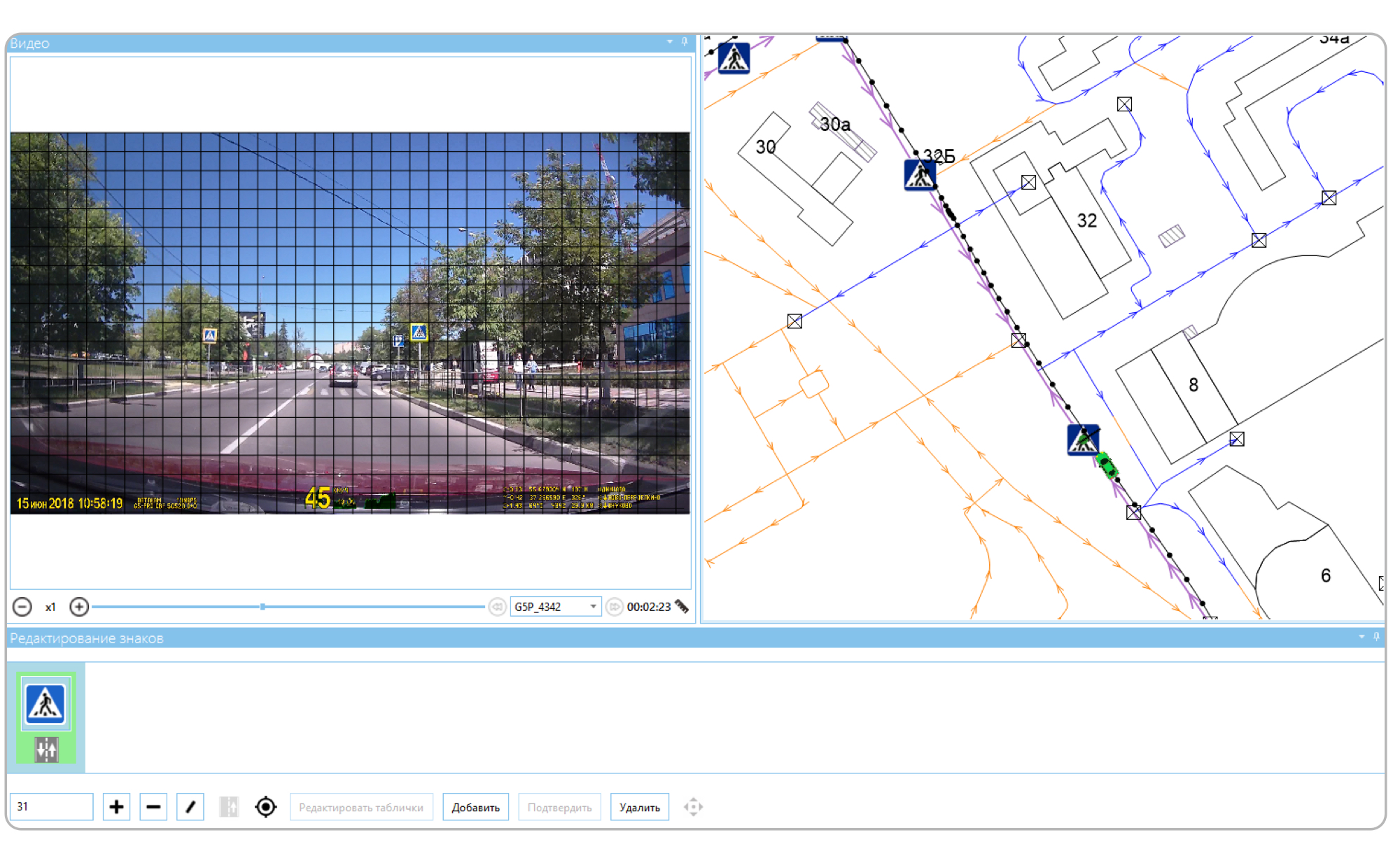
A grid is applied on top of the video - it allows you to determine the distance to the sign. As soon as the character becomes the size of a cell, the cartographer pauses and creates the character. At this moment, we know the current position and the distance to the sign, so we move it forward and draw it to the link. The link in our terminology is a schematic representation of a road section. Each character has its own numerical code, its cartographer enters in a special field.
If we have already entered a character, then we load it into the character editor. The cartographer checks the video and, if necessary, makes changes using the same numerical codes. Or, if the sign is correct, marks it as updated.
Of course, this method requires the cartographer to view each video - and then also spend time on entering each character. In addition, the position of the sign on the map is not accurately determined: we simply deviate from the current position by a distance that is determined by the grid, and then we draw the resulting point to the nearest road. As a result, signs may not be created exactly there (or even not at all) where necessary. This means that the cartographer must also move him to the right place, which also consumes his time. In addition, the video may not have any signs at all, but the cartographer is still forced to view it. Of course, the program allows you to increase the speed of the video, but the time cost in any case will be more than zero. Therefore, we decided to automate this process.
How to collect now
We still need registrar videos. But now, instead of looking at each one, the cartographer simply selects the necessary files and presses the "Download" button. After that, he can do other things - the video will be processed and road signs will appear on the map. Various dubious cases will be specifically noted. Therefore, all that remains for the cartographer is to go over these cases and correct them.
Architecture
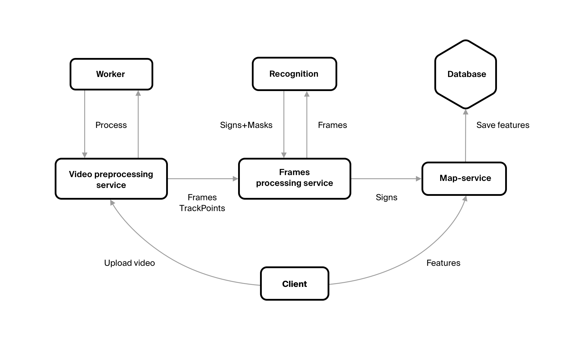
In order to get objects of the required classes with the necessary attributes from the video, we wrote several services.
The first is VideoPreprocessingService - this is where the video file is uploaded. The service sends the file to the repository, makes a record about it in the database, and creates tasks for its processing. You need to cut frames from the video with a certain frequency, select GPS points for them from the track for them, send the result to the Frames Processing service.
The first two tasks are performed not by the service itself, but by Worker. This is done so that you can easily change the number of these workers. Thus increasing productivity, if there is such a need.
FrameProcessingService saves itself all received frames and points. He also uploads frames to the queue. It is read by a service written by our fellow Machine Learning experts. He recognizes traffic signs. Of course, FrameProcessingService reads the responses from this service - these are the codes of characters, if they are on the frame, and the rectangles in which this character is inscribed. Knowing the size of the rectangle, we understand the distance to the sign. And when all the frames from the video are processed - he sends them to our map server.
The map server is the most important part of the system. Clients receive from him all the data that we store ( except for tiles ). He saves this data and executes all the business logic.
general description
Our map data is geo objects. A geo object is a geometry (that is, the location of an object in space) and a set of attributes. We store them in the database and operate on them. But from FrameProcessingService we get only the sign code, the coordinates of the point from which the sign was recognized, the frame itself and the sign mask on this frame. So we need to turn this data set into a geo object. Each geo object belongs to some class. Each type of road sign is a separate class. We can easily get it from the sign code. From the sign code we can get attributes specific to this class. For example, we received the code 3_24_60. 3_24 - says that this is a speed limit (sign 3.24 in traffic rules). The restriction value must be indicated for these characters. He tells us the third part of the code - here it will be 60 km / h.
So, the geo object class is defined, its attributes are specific too. It would seem that you can already create a geo object. But it’s too early. Firstly, each sign has an attribute “Direction”, which says in which direction the sign acts. Secondly, we still do not have geometry for this geo object. We have a point from which we saw a sign. So, the sign itself is at some distance from us. In addition, its geometry affects the value of the Direction attribute.

Here we will make a small digression. Of course, we have a road network. It consists of individual links. Each link is a line. In the first part of the figure we have just drawn two links. The arrows show the direction in which they were drawn, i.e. the left was drawn from the bottom up, and the right - from top to bottom.
Each link carries information about in which direction you can move along it. The direction of movement is a separate attribute; it is not equal to the direction of rendering. This attribute tells us in which direction you can move along the link, relative to the drawing direction. In the second part of the figure, both links have the same value for this attribute, and in the third figure - opposite values.
How does this relate to signs? So, we move along the links from the bottom up, and we see some kind of sign. So, on the left link the sign will have the direction “Only straight”, on the right — “Only back”, i.e. same as the links in the third figure. Everything turned out simple here, but this is because our links are one-way. In reality, a very large number of links are bilateral, i.e. their direction has the meaning of "In both directions." And the sign is always directed in one direction, and we need to understand which direction.
Map matching
Before starting to place signs on the map, we need to understand what roads we drove when we recorded the video. GPS data are not enough for this: it is often mistaken for tens of meters. In addition, maps are still schemes and may also not coincide with real terrain. For example, on wide multi-lane roads.
This will solve a number of problems at once:
- Signs can already be created on these roads, so we can make changes to them, if any;
- Some of these signs may not appear on the video, and we can find such signs - and put them a special label;
- We can understand what road we were on when we saw some recognized sign, which, in turn, will help us put this sign in the right place on the map.
Algorithm
The algorithm we used is pretty simple. There is already an article on Habré with his description. In general terms, it sounds like this: we have a selected road, take the GPS point closest to its end from the track. And regarding this point, we evaluate the roads that join our path - that is, we evaluate how likely it is that our point refers to this particular road. Each road receives points, the one with the most points is selected. Repeat until the track ends.
In the process, we made several additions to the algorithm. The algorithm did not take into account the direction on the road links, so the first thing we did was start to take them into account: now, if the link is one-way, we understand what direction we should move along it. And if this direction does not coincide with the direction of the link, we discard this link.
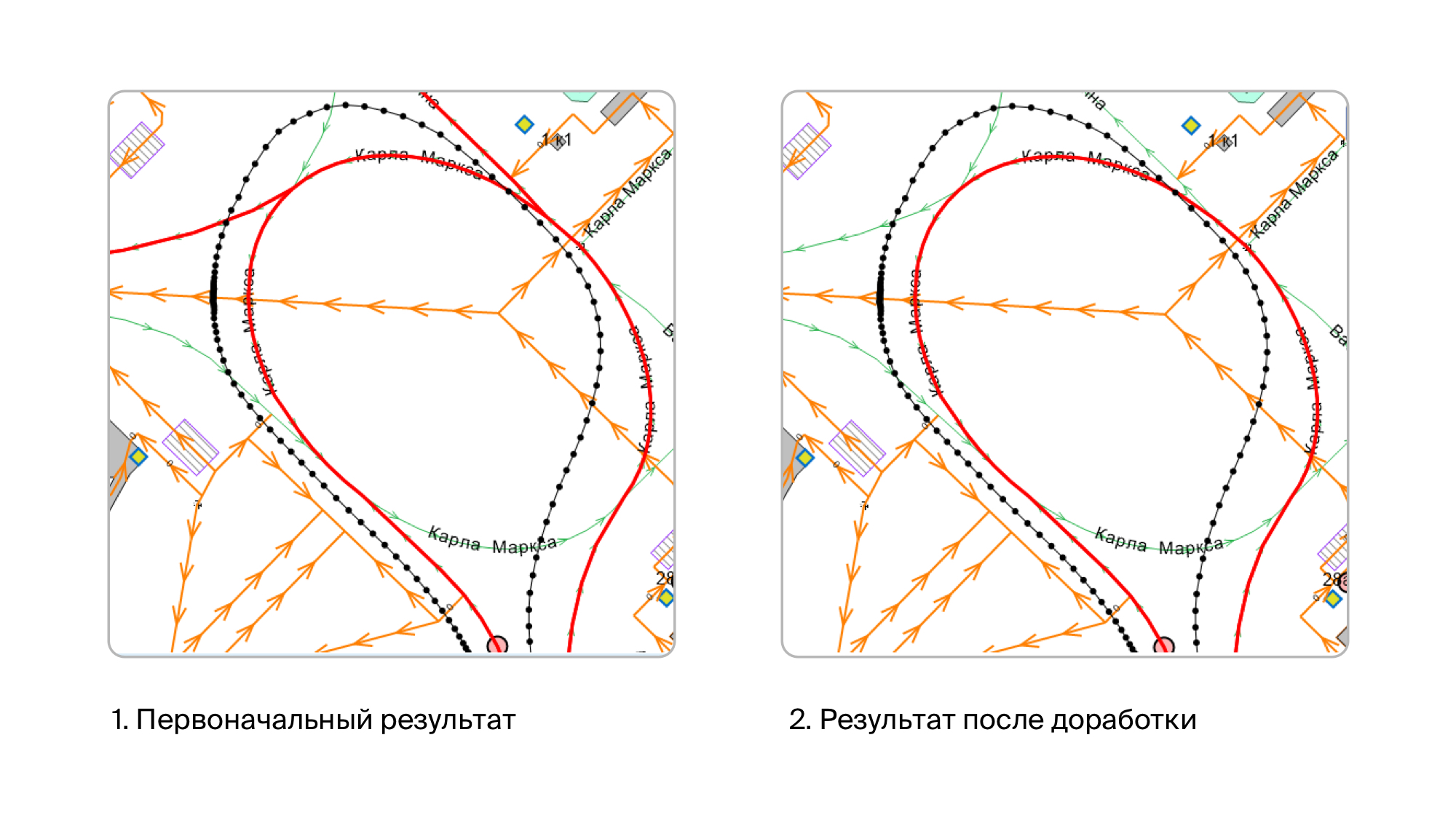
Initially, it seemed to us that this would be enough, and the first tests confirmed this. But then we began to check the videos recorded in residential neighborhoods, and everything turned out not so rosy. The fact is that we have very high data accuracy, including on roads. Accordingly, we have drawn all the intra-quarter driveways, down to the smallest detail. On the other hand - as I said, GPS may not be very accurate or even very inaccurate. And if you go on a road around which there are tall buildings, then the points in the track can leave quite strongly. It used to happen that the points moved toward more than 20 meters. As a result, it turns out that many points are close to those roads on which we did not go. The result of the shrinkage of such tracks was this picture:
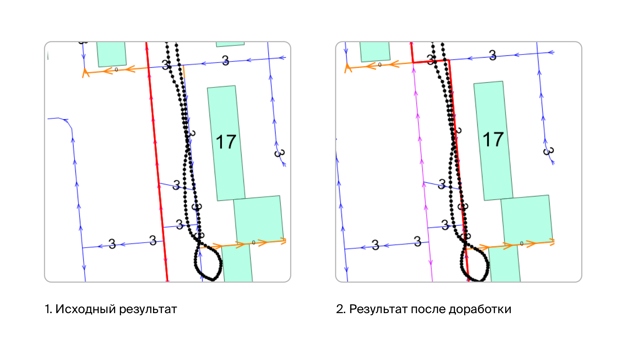
Common sense told us that there are few signs on such roads, and therefore there is no particular reason to collect them there. Therefore, most likely, in most cases, the car moved along the main streets. Therefore, for intra-quarter driveways, we introduced a fine. By a fine we mean a decrease in the number of points along the road. As a result, the problem with intra-quarter driveways was resolved - they didn’t get out when we didn’t go along them, and when we really went along them, even despite the fine, they turn out to be the best option and then we choose them.
After that, the results were already very good. And it seemed to us that mapmatching was over. But the trouble came, from where they did not wait. Quite suddenly it turned out that there are cases when another road branches off from the road, and does it very smoothly. And everything was aggravated by the fact that the branch road can also go in parallel with ours, at least for some time. At the same time, I remind you, the GPS track is almost never located on top of the links we traveled to, it is slightly offset to some side of it. And of course, thanks to all this, the algorithm began to cling to these branches. Because of which, at best, we received several links that we didn’t actually go through. And in the worst - they seated the track quite wrong.
Therefore, we came up with an additional assessment of the road. We take the previous and next points of the GPS track relative to the point from which we selected the link. And we see that the azimuth at these points does not differ too much from the azimuth of movement along this link. If it differs greatly, we fine this link.
As a result, we got a result that suits us, although sometimes small errors still occur (sometimes an extra link can be chosen that we didn’t go through). But they are quite rare, and therefore not critical for us.
Character placement
Now we have a set of road links on which we drove, and a set of frames with signs. As well as information about which character is on this frame, from which point on the track this frame and the mask of the character are obtained (a rectangle that describes the character on this frame). So you can place these signs on the map.
The first step is to get additional information that will help us put the sign in the right place:
- Azimuth sign. If the mark is located exactly in the center of the frame, it coincides with the azimuth at the GPS point. If the sign is not centered, this is the azimuth at the point + the angle between the center of the frame and the sign. We already have the azimuth of the GPS point, and we can calculate the angle between the center of the frame and the sign, because we know where the sign mask is located on the frame and we know the viewing angle with which the video was recorded.
- The distance to the mark from the GPS point. We can calculate it, because we know the size of the sign mask, the resolution of the frame and the viewing angle with which the video is recorded.
Now you can go directly to the installation of the sign. Because points on the track do not always (but actually never) lie on the road links, first we need to put our sign detection point on the link. We do it as follows:
- Among the roads on which the track was seated, we leave only those that cross some kind of buffer around our GPS point;
- We calculate the distance to each selected road and sort them by its increasing;
- We take the road, calculate the projection of the GPS point on it;
- We get the direction with which we move at this point along this road;
- If the direction from item 4 is unacceptable on this road, then we return to item 3 and take the next road there;
- If the direction is acceptable, then stop.
Now we have the road we took when we set the GPS point, and the projection of this point onto our road. In fact, this road, and hence the point, may not be chosen correctly. For example, when cornering, it is very easy to make a mistake.

Therefore, before moving on, you need to make sure that we are not mistaken. Or, if you make a mistake, replace the road with the right one and get a projection onto it. To do this, take the roads that connect to our road and evaluate them by distance and azimuth. As a result, we get the road that is best suited for a given point and construct a projection onto it.
Now that our GPS point is pulled to the road, we can calculate the location of the sign relative to it. To do this, build a vector from this point with a length equal to the distance to the sign in the direction coinciding with the sign azimuth. After that, we try to pull the sign to one of the roads on which our track was seated. In this case, we take into account the direction of the roads and the direction of the sign, which is calculated for each road through the azimuth of the sign.
At this stage, it may turn out that there was no suitable road. For example, due to the fact that the sign will have a direction that is unacceptable on these roads (i.e., they are one-way). In this case, this sign is located on some neighboring road on which we did not pass, which means that we simply will not create it.
Now we have the coordinate of the sign drawn to the road, it remains to verify that it is set appropriately, because sometimes we can make a mistake. To do this, we verify that the sign is not too far from the original GPS point by comparing this distance with the distance to the sign obtained through the frame, with some assumption. Also check that the mark is not behind the GPS point. If the validations are successful, we got the coordinates of the sign on the road and its direction, which means that our geo object has geometry and all the necessary attributes. You can proceed to save it.
Merge signs
In fact, it’s too early to move on to conservation. The fact is that each sign can be seen from several frames, with the exception of some special cases, when for some parts of the frame the sign is hidden behind any obstacle, for example, behind a truck.
From each of these frames we got a geo object for the sign, they have the same attributes and they are located at about the same point. This means that we need to leave only one of them. In addition, if this sign is not new, then we already have it in the database, which means we need to mark it that it is updated, and not create a new geo object.
For this, we carry out merge of new geo objects between ourselves and with existing ones.
First of all, we get all the signs that we have already created, on the links on which we drove. To them we add all the characters that we recognized from the frames.
What we need to do with them: we need to understand from their classes, attributes and geometries that some set of these geo objects is the same sign. If there is an existing geo object in this set, leave only it and note that it has been updated. If the set contains only new geo objects, leave only one of them.
We do this in four steps:
- Group geo objects by their class;
- In each group from step 1 we obtain groups by attributes;
- For each group from step 2, we collect the groups by geometry;
- If there is an existing sign in the group from step 3, we leave only it (if there are several of them, then leave them all), and if there are no existing signs in the group, we leave the one that is in the middle.
After that, we have the desired number of characters that can finally be saved.

Of course, it may turn out that we have some kind of sign, but we did not recognize it with the video. In this case, this symbol will not be updated. Unfortunately, we cannot be sure that this sign is also no longer on the ground, because it could just be covered by some kind of obstacle while recording a video. Therefore, we do not delete this sign immediately, but mark it as missing on the video. If this sign is visible on some other video, then we simply remove this mark from it and update it. If he still will not be visible - the cartographer will have to deal with this sign. And delete it if it really is no more.
Immediate plans
Signs from the side roads
Signs on the video not only come from the roads that we drive, but also from the side roads: these may be roads that cross ours or that adjoin ours. Or vice versa - roads that branch off ours. It can even be roads that are parallel to ours. It is very difficult to distinguish the signs that stand on these roads from the signs that we need. After all, often they are close to our road.
To solve the problem, we plan to use a number of semantic rules when placing a sign on a link. For example, a speed limit of 5km / h is unlikely to be on the highway, but very likely it will be at the entrance to the gas station.
Tracking signs
Sometimes we do not keep signs, and sometimes vice versa - we hold signs that do not need to be merged. Therefore, we plan to track characters by frames - in order to recognize the same character on different frames even before we turn them into geo objects. And use this knowledge with merge.
Conclusion
The current version is essentially beta. Therefore, it is imperfect. There are problems that we are going to solve in the near future. There are problems that are still unclear how to solve. And there are those that are generally unlikely to be solved using algorithms. For example, GPS tracks can be of very poor quality. Or a video where the image and track are out of sync - and this can be understood only by watching it. In general, the task turned out to be much more complicated than we originally expected.
We have a huge field for solving various problems. So, we will decide. And of course, to tell if we stumble upon something interesting.