This article has too much water.
“We are starting to develop a new game, and we need cool water. That you can? ”
- asked me. "Sure, not a problem! Of course I can, ”I replied, but my voice trembled treacherously. "And, also on Unity?", - and it became clear to me that there is a lot of work ahead.
So, a little water. Unity until that moment I didn’t see, exactly like C #, so I decided that I would do a prototype on tools I’m familiar with: C ++ and DX9. What I knew and was able to practice at that time was the scrolling textures of normals for surface formation, and a primitive displacement mapping based on them. Immediately you had to change everything. Realistic animated shape of the water surface. Complicated (strongly) shading. Foam generation. LOD system tied to the camera. I began to seek information on the Internet how to do all this.
The first item, of course, was an understanding of Jerry Tessendorf's "Simulating Ocean Water" .
Academic papers with a bunch of abstruse formulas have never been given to me especially, so after a couple of readings I understood little. The general principles were clear: each frame generated a height map using the Fast Fourier Transform, which, as a function of time, smoothly changes its shape to form a realistic water surface. But how and what to count, I did not know. I slowly delved into the wisdom of the FFT miscalculation on the shaders in D3D9, and the source code helped me with this article somewhere in the wilds of the Internet, which I tried to find for an hour, but without success (unfortunately). The first result was obtained (terrible as a nuclear war):
Starting progress pleased, and the transfer of water to Unity began with its refinement.
To the water in the game about the sea battle put forward several requirements:
It was decided to build a quadtree-like structure with a center around the camera, which is discretely rebuilt as the observer moves. Why discrete? If you move the mesh smoothly with the camera or use screen space reprojection as in the article Real-time water rendering - introducing the projected grid conceptthen on distant plans due to insufficient resolution of the geometric grid, when sampling the height map, waves will “jump” up and down polygons. This is very striking. Picture "ripples." To overcome this, it is necessary either to greatly increase the resolution of the polygonal mesh of the water mesh, or to “flatten” the geometry at long distances, or to build and move polygons so that these shifts are not visible. We have progressive water (hehe) and I chose the third way. As with any such technique (especially familiar to everyone who created terrain in games), you need to get rid of T-junctions at the boundaries of the levels of detail. To solve this problem, 3 types of quads with the specified tessellation parameters are calculated at the start:

The first type is for those quads that are not transitional to lower details. Neither side has a 2 times reduced number of vertices. The second type is for boundary, but not angular quads. The third type is angular boundary quads. The final water mesh is constructed by rotating and scaling these three kinds of meshes.
This is how the render with backlighting in different color LOD water levels looks like.
The first frames show the connection of two different levels of detail.
Video as a frame is filled with water quads:
Let me remind you, it was all a long time ago (and not true). Now more optimally and flexibly can be done immediately on the GPU (GPU Pro 5. Quadtrees on the GPU). And it will draw in one draw call, and tessellation can raise the detail.
Later, the project moved to D3D11, but the hands did not reach the upgrade of this part of the ocean render.
For this we need the Fast Fourier Transform. For the selected (desired) resolution of the wave texture (for the time being we call it this way, I will explain what data is stored there) prepare the initial data using the parameters set by the artists (force, wind direction, wave dependence on wind direction, etc.) All this must be fed into the formulas of the so-called. Phillips spectrum The received initial data is modified each frame with the account of time and we execute FFT over them. At the output we get a texture that is tiled in all directions, which contains the offset of the vertices of the flat mesh. Why not just heightmap? If you store only the offset height, then the result will be an unrealistic "seething" mass, only remotely resembling the sea:
If we consider the displacements for all three coordinates, then beautiful “sharp” realistic waves will be generated:
One animated texture is not enough. Visible tiling, not enough details in the near future. We take the described algorithm and make not one, but 3 fft-generated textures. The first is large waves. It sets the basic waveform and is used for physics. The second is medium waves. And finally, the smallest. 3 FFT generator (4th version is the final mix):
Layer parameters are set independently of each other, and the resulting textures are mixed in the water shader into the final waveform. In parallel with the offsets, the normal maps of each layer are also generated.
The "uniformity" of water for all participants in the battle is provided by the synchronization of the parameters of the ocean at the start of the battle. This information is transmitted by the server to each client.
Since it was necessary to make not only a beautiful picture, but also a realistic behavior of the ships. And also considering that the storm sea must be present in the game (large waves), another task that needed to be solved was to ensure the buoyancy of objects on the surface of the generated sea. At first I tried to make the GPU readback texture waves. But, since it quickly became clear that the whole physics of naval combat needed to be done on the server, then the sea, or rather its first layer that sets the shape of the wave, must also be read on the server (and most likely there is no fast and / or compatible GPU), it was decided to write a full functional copy of the GPU FFT generator, on the CPU in the form of a native C ++ plug-in to Unity. I myself did not implement the FFT algorithm and used it in the Intel Performance Primitives (IPP) library. But all the binding and postprocessing of the results was performed by me, followed by optimization on SSE and threading along threads. This included the preparation of an array of data for FFT each frame, and the final conversion of the calculated values into a wave offset map.
There was another interesting feature of the algorithm, which was based on the requirements for water physics. The function needed to quickly obtain the height of the wave at a given point in the world. It is logical, because this is the basis for constructing the buoyancy of any object. But, since the output of the FFT processor yields an offsetmap, not a heightmap, the usual sampling from the texture did not give us the wave height where necessary. For simplicity, consider the 2D version:

To form a wave, texels (textural elements shown by vertical lines) contain a vector (arrows) which sets the displacement of the vertex of the flat mesh (blue dots) in the direction of its final position (arrowhead). Suppose we take this data and try to extract from it the height of the water at the point of interest. For example, we need to know the height at hB. If we take a vector in tB, we get an offset to a point near hC, which can be very different from what we need. There are two options for solving this problem: check the set of adjacent texels with each height request until we find one that has an offset to the position of interest. In our example, we find the texel tA as containing the closest offset. But this approach can not be called fast. Scanning the radius of texels is unclear what size (and what
The second option - after calculating the offset map to convert it into a height map, using the scattering approach. This means that for each offset vector, we write the height of the wave, which it sets, to the point where it is shifted. This will be a separate data array, which will be used to obtain the height at the point of interest. Using our illustration, the tB cell will contain the height hB obtained from the vector tA → hB. There is another feature. The tA cell will not contain valid values, since there is no vector shifting into it. To fill such “holes”, a passage of filling them with adjacent values is performed.
This is what it looks like if you render the displacement visualization with the help of vectors (red - large displacement, green - small):
Then everything is simple. For the ship, the plane of the conditional waterline is set. It defines a rectangular grid of sample points, which specifies the places of application of forces pushing out of the water for the ship. Then, for each point, we check if it is underwater using the water heightmap described above. If a point is under water, then we apply a vertical force upwards to the body hull physics hull at this point, scaled by the distance from the point to the water surface. If above water, then we do nothing, gravity will do everything for us. In fact, the formulas there are a bit more complicated (all for fine tuning of the ship's behavior), but the basic principle is as follows. In the buoyancy visualization video below, the blue cubes are the locations of the samples, and the lines from them down are the magnitude of the force pushing out of the water.
There is one more interesting optimization moment in the server implementation. There is no need to simulate different water for different combat instances, if they are held in the same weather conditions (the same parameters of the FFT simulator). So the logical solution was to make a pool of simulators, to which the combat instances fulfill requests for receiving simulated water with the given parameters. If the parameters are the same from several instances, then the same water will return to them. This is implemented using the Memoru Mapped File API. When an FFT simulator is created, it gives access to its data by exporting the desired block descriptors. The server instance, instead of running a real simulator, runs a “dummy” that simply gives away the data opened by these descriptors. There were some funny bugs related to this functionality. Due to reference counting errors, the simulator was destroyed, but the memory mapped file is alive while at least one handle is open to it. The data stopped being updated (there is no simulator) and the water “stopped”.
On the client side, we need information about the shape of the wave in order to calculate the number of hits of the nuclei in the wave and play systems of particles and foam. Damage miscalculation occurs on the server and there it is also necessary to correctly determine whether the core fell into the water (a wave can close the ship, especially in storms). Here it is necessary to do heightmap tracing by analogy as it is done in parallax mapping or SSAO effects.
In principle, as elsewhere. Reflections, refractions, subsurface scattering slyly knead, given the depth of the bottom, we take into account the fresnel effect, we consider the speculator. Scattering believe for ridges depending on the position of the sun. The foam is generated as follows: we create a “foam spot” on the crests of the waves (we use height as a metric), then we impose newly created spots on the spots from the previous frames while simultaneously reducing their intensity. Thus, we obtain a smearing of foam spots in the form of a tail from a traveling wave crest.
We use the resulting texture "spots" as a mask to which we mix the textures of bubbles, streaks, etc. We get a rather realistic dynamic foam pattern on the surface of the waves. This mask is created for each FFT layer (remember, we have 3 of them), and they all mix in the final mix.
In the video above, the foam mask visualization. The first and second layers. I modify the parameters of the generator and the result is visible on the texture.
And the video is a little clumsy tuned stormy sea. Here you can clearly see the waveform, the possibilities of the generator and foam:
Picture example of use:
Used for:
The obvious base case is projective texturing. It was implemented. But then there were additional requirements. Near species are soap due to insufficient resolution (it can be enlarged, but not infinitely), and I want to see these projective patterns on the water far away. Where is the same problem solved? Correctly, in shadows (shadow map). How is she solved there? That's right, Cascaded (Parallel Split) Shadow Maps. We will take this technology into service and apply it to our task. We divide the frustum of the camera into N (3-4 usually) subfrustums. For each build a descriptive rectangle in the horizontal plane. For each such rectangle, we build an orthographic projection matrix and draw all the objects of interest for each of the N such ortho chambers. Each such camera draws in a separate texture, and then, in the ocean shader,
So I put on the sea a huge plane with the texture of flags:

This is what is contained in the splits:
In addition to the usual pictures, you need to draw in the same way an additional foam mask (for traces of ships and nuclear hit points), as well as a mask for squeezing water under ships. This is a lot of cameras and many passes. At first, it was so slow and worked, but then, after switching to D3D11, by replicating geometry in a geometric shader and drawing each copy into a separate render target via SV_RenderTergetArrayIndex, this effect was greatly accelerated.
D3D11 unleashes hands in many moments. After switching to Unity 5, I made an FFT generator on сompute shaders. Visually, nothing has changed, but it was a little faster. Translation rendering texture reflections from a separate full-fledged camera render to Screen Space Planar Reflections technology gave a good boost to performance. I wrote about the optimization of water surface objects above, and my hands never reached the transfer of the mesh to the Quadtree GPU.
Much, perhaps, could be made more optimal and easier. For example, do not fence gardens with a CPU simulator, but simply run the GPU version on the server with a WARP (software) d3d device. Data arrays there are not very large.
Well, in general, something like that. While the development began, it was all modern and cool. Already in some places it is getting older. There are more materials available, even there is a similar counterpart on github: Crest . In most games where there are seas, a similar approach is used.
- asked me. "Sure, not a problem! Of course I can, ”I replied, but my voice trembled treacherously. "And, also on Unity?", - and it became clear to me that there is a lot of work ahead.
So, a little water. Unity until that moment I didn’t see, exactly like C #, so I decided that I would do a prototype on tools I’m familiar with: C ++ and DX9. What I knew and was able to practice at that time was the scrolling textures of normals for surface formation, and a primitive displacement mapping based on them. Immediately you had to change everything. Realistic animated shape of the water surface. Complicated (strongly) shading. Foam generation. LOD system tied to the camera. I began to seek information on the Internet how to do all this.
The first item, of course, was an understanding of Jerry Tessendorf's "Simulating Ocean Water" .
Academic papers with a bunch of abstruse formulas have never been given to me especially, so after a couple of readings I understood little. The general principles were clear: each frame generated a height map using the Fast Fourier Transform, which, as a function of time, smoothly changes its shape to form a realistic water surface. But how and what to count, I did not know. I slowly delved into the wisdom of the FFT miscalculation on the shaders in D3D9, and the source code helped me with this article somewhere in the wilds of the Internet, which I tried to find for an hour, but without success (unfortunately). The first result was obtained (terrible as a nuclear war):
Starting progress pleased, and the transfer of water to Unity began with its refinement.
To the water in the game about the sea battle put forward several requirements:
- Realistic appearance. Beautiful both close and distant angles, dynamic foam, scattering, etc.
- Support for various weather conditions: calm, storm and intermediate states. Change the time of day.
- Physics of ships buoyancy on simulated surface, floating objects.
- Since the game is multiplayer, the water should be the same for all combat participants.
- Drawing on the surface: drawn zones of flight of the nuclei of a volley, foam from hits of nuclei into the water.
Geometry
It was decided to build a quadtree-like structure with a center around the camera, which is discretely rebuilt as the observer moves. Why discrete? If you move the mesh smoothly with the camera or use screen space reprojection as in the article Real-time water rendering - introducing the projected grid conceptthen on distant plans due to insufficient resolution of the geometric grid, when sampling the height map, waves will “jump” up and down polygons. This is very striking. Picture "ripples." To overcome this, it is necessary either to greatly increase the resolution of the polygonal mesh of the water mesh, or to “flatten” the geometry at long distances, or to build and move polygons so that these shifts are not visible. We have progressive water (hehe) and I chose the third way. As with any such technique (especially familiar to everyone who created terrain in games), you need to get rid of T-junctions at the boundaries of the levels of detail. To solve this problem, 3 types of quads with the specified tessellation parameters are calculated at the start:
The first type is for those quads that are not transitional to lower details. Neither side has a 2 times reduced number of vertices. The second type is for boundary, but not angular quads. The third type is angular boundary quads. The final water mesh is constructed by rotating and scaling these three kinds of meshes.
This is how the render with backlighting in different color LOD water levels looks like.
The first frames show the connection of two different levels of detail.
Video as a frame is filled with water quads:
Let me remind you, it was all a long time ago (and not true). Now more optimally and flexibly can be done immediately on the GPU (GPU Pro 5. Quadtrees on the GPU). And it will draw in one draw call, and tessellation can raise the detail.
Later, the project moved to D3D11, but the hands did not reach the upgrade of this part of the ocean render.
Waveform generation
For this we need the Fast Fourier Transform. For the selected (desired) resolution of the wave texture (for the time being we call it this way, I will explain what data is stored there) prepare the initial data using the parameters set by the artists (force, wind direction, wave dependence on wind direction, etc.) All this must be fed into the formulas of the so-called. Phillips spectrum The received initial data is modified each frame with the account of time and we execute FFT over them. At the output we get a texture that is tiled in all directions, which contains the offset of the vertices of the flat mesh. Why not just heightmap? If you store only the offset height, then the result will be an unrealistic "seething" mass, only remotely resembling the sea:
If we consider the displacements for all three coordinates, then beautiful “sharp” realistic waves will be generated:
One animated texture is not enough. Visible tiling, not enough details in the near future. We take the described algorithm and make not one, but 3 fft-generated textures. The first is large waves. It sets the basic waveform and is used for physics. The second is medium waves. And finally, the smallest. 3 FFT generator (4th version is the final mix):
Layer parameters are set independently of each other, and the resulting textures are mixed in the water shader into the final waveform. In parallel with the offsets, the normal maps of each layer are also generated.
The "uniformity" of water for all participants in the battle is provided by the synchronization of the parameters of the ocean at the start of the battle. This information is transmitted by the server to each client.
Physical model of buoyancy
Since it was necessary to make not only a beautiful picture, but also a realistic behavior of the ships. And also considering that the storm sea must be present in the game (large waves), another task that needed to be solved was to ensure the buoyancy of objects on the surface of the generated sea. At first I tried to make the GPU readback texture waves. But, since it quickly became clear that the whole physics of naval combat needed to be done on the server, then the sea, or rather its first layer that sets the shape of the wave, must also be read on the server (and most likely there is no fast and / or compatible GPU), it was decided to write a full functional copy of the GPU FFT generator, on the CPU in the form of a native C ++ plug-in to Unity. I myself did not implement the FFT algorithm and used it in the Intel Performance Primitives (IPP) library. But all the binding and postprocessing of the results was performed by me, followed by optimization on SSE and threading along threads. This included the preparation of an array of data for FFT each frame, and the final conversion of the calculated values into a wave offset map.
There was another interesting feature of the algorithm, which was based on the requirements for water physics. The function needed to quickly obtain the height of the wave at a given point in the world. It is logical, because this is the basis for constructing the buoyancy of any object. But, since the output of the FFT processor yields an offsetmap, not a heightmap, the usual sampling from the texture did not give us the wave height where necessary. For simplicity, consider the 2D version:
To form a wave, texels (textural elements shown by vertical lines) contain a vector (arrows) which sets the displacement of the vertex of the flat mesh (blue dots) in the direction of its final position (arrowhead). Suppose we take this data and try to extract from it the height of the water at the point of interest. For example, we need to know the height at hB. If we take a vector in tB, we get an offset to a point near hC, which can be very different from what we need. There are two options for solving this problem: check the set of adjacent texels with each height request until we find one that has an offset to the position of interest. In our example, we find the texel tA as containing the closest offset. But this approach can not be called fast. Scanning the radius of texels is unclear what size (and what
The second option - after calculating the offset map to convert it into a height map, using the scattering approach. This means that for each offset vector, we write the height of the wave, which it sets, to the point where it is shifted. This will be a separate data array, which will be used to obtain the height at the point of interest. Using our illustration, the tB cell will contain the height hB obtained from the vector tA → hB. There is another feature. The tA cell will not contain valid values, since there is no vector shifting into it. To fill such “holes”, a passage of filling them with adjacent values is performed.
This is what it looks like if you render the displacement visualization with the help of vectors (red - large displacement, green - small):
Then everything is simple. For the ship, the plane of the conditional waterline is set. It defines a rectangular grid of sample points, which specifies the places of application of forces pushing out of the water for the ship. Then, for each point, we check if it is underwater using the water heightmap described above. If a point is under water, then we apply a vertical force upwards to the body hull physics hull at this point, scaled by the distance from the point to the water surface. If above water, then we do nothing, gravity will do everything for us. In fact, the formulas there are a bit more complicated (all for fine tuning of the ship's behavior), but the basic principle is as follows. In the buoyancy visualization video below, the blue cubes are the locations of the samples, and the lines from them down are the magnitude of the force pushing out of the water.
There is one more interesting optimization moment in the server implementation. There is no need to simulate different water for different combat instances, if they are held in the same weather conditions (the same parameters of the FFT simulator). So the logical solution was to make a pool of simulators, to which the combat instances fulfill requests for receiving simulated water with the given parameters. If the parameters are the same from several instances, then the same water will return to them. This is implemented using the Memoru Mapped File API. When an FFT simulator is created, it gives access to its data by exporting the desired block descriptors. The server instance, instead of running a real simulator, runs a “dummy” that simply gives away the data opened by these descriptors. There were some funny bugs related to this functionality. Due to reference counting errors, the simulator was destroyed, but the memory mapped file is alive while at least one handle is open to it. The data stopped being updated (there is no simulator) and the water “stopped”.
On the client side, we need information about the shape of the wave in order to calculate the number of hits of the nuclei in the wave and play systems of particles and foam. Damage miscalculation occurs on the server and there it is also necessary to correctly determine whether the core fell into the water (a wave can close the ship, especially in storms). Here it is necessary to do heightmap tracing by analogy as it is done in parallax mapping or SSAO effects.
Shading
In principle, as elsewhere. Reflections, refractions, subsurface scattering slyly knead, given the depth of the bottom, we take into account the fresnel effect, we consider the speculator. Scattering believe for ridges depending on the position of the sun. The foam is generated as follows: we create a “foam spot” on the crests of the waves (we use height as a metric), then we impose newly created spots on the spots from the previous frames while simultaneously reducing their intensity. Thus, we obtain a smearing of foam spots in the form of a tail from a traveling wave crest.
We use the resulting texture "spots" as a mask to which we mix the textures of bubbles, streaks, etc. We get a rather realistic dynamic foam pattern on the surface of the waves. This mask is created for each FFT layer (remember, we have 3 of them), and they all mix in the final mix.
In the video above, the foam mask visualization. The first and second layers. I modify the parameters of the generator and the result is visible on the texture.
And the video is a little clumsy tuned stormy sea. Here you can clearly see the waveform, the possibilities of the generator and foam:
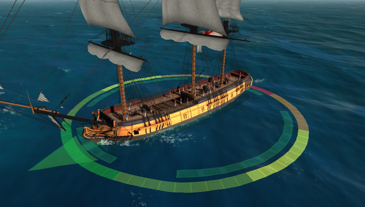
Drawing on the water surface
Picture example of use:
Used for:
- Markers, visualization of the nuclear expansion zone.
- Drawing the foam at the point of entry of nuclei into the water.
- Foam trail behind the ship
- Squeezing the water under the ship to remove the effect of pouring the waves of the deck and flooded hold.
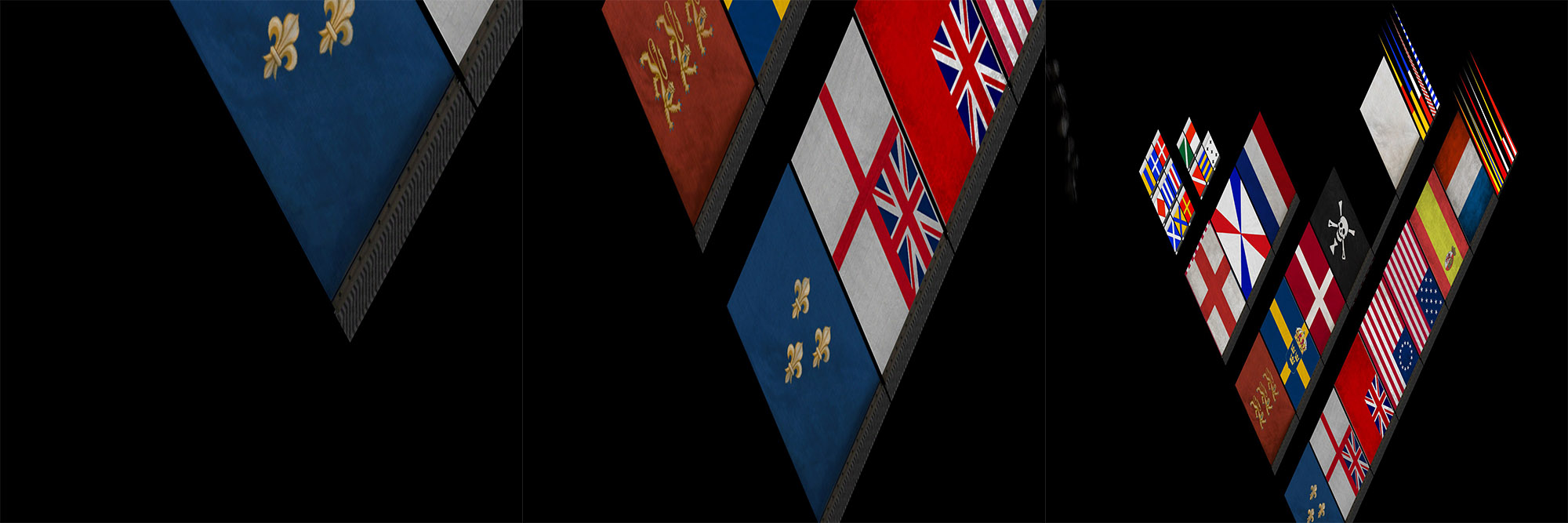
The obvious base case is projective texturing. It was implemented. But then there were additional requirements. Near species are soap due to insufficient resolution (it can be enlarged, but not infinitely), and I want to see these projective patterns on the water far away. Where is the same problem solved? Correctly, in shadows (shadow map). How is she solved there? That's right, Cascaded (Parallel Split) Shadow Maps. We will take this technology into service and apply it to our task. We divide the frustum of the camera into N (3-4 usually) subfrustums. For each build a descriptive rectangle in the horizontal plane. For each such rectangle, we build an orthographic projection matrix and draw all the objects of interest for each of the N such ortho chambers. Each such camera draws in a separate texture, and then, in the ocean shader,
So I put on the sea a huge plane with the texture of flags:
This is what is contained in the splits:
In addition to the usual pictures, you need to draw in the same way an additional foam mask (for traces of ships and nuclear hit points), as well as a mask for squeezing water under ships. This is a lot of cameras and many passes. At first, it was so slow and worked, but then, after switching to D3D11, by replicating geometry in a geometric shader and drawing each copy into a separate render target via SV_RenderTergetArrayIndex, this effect was greatly accelerated.
Improvements and upgrades
D3D11 unleashes hands in many moments. After switching to Unity 5, I made an FFT generator on сompute shaders. Visually, nothing has changed, but it was a little faster. Translation rendering texture reflections from a separate full-fledged camera render to Screen Space Planar Reflections technology gave a good boost to performance. I wrote about the optimization of water surface objects above, and my hands never reached the transfer of the mesh to the Quadtree GPU.
Much, perhaps, could be made more optimal and easier. For example, do not fence gardens with a CPU simulator, but simply run the GPU version on the server with a WARP (software) d3d device. Data arrays there are not very large.
Well, in general, something like that. While the development began, it was all modern and cool. Already in some places it is getting older. There are more materials available, even there is a similar counterpart on github: Crest . In most games where there are seas, a similar approach is used.