Product Development Visual Aid: Design
This is the third of four articles on the development of physical products. If you missed Part 1: Forming an idea , or Part 2: Design , it is worth reading them. You will soon be able to move on to Part 4: Validation. Posted by: Ben Einstein. The original translation was made by the teams of the fablab FABINKA and the HAND project .
Each step at the design stage (development of technical requirements, creation of a functioning prototype, programming of firmware / software) is needed to make sure that the product is functioning reliably and its production cost is optimal. The result of the engineering development process is a prototype that functions correctly, but does not yet have good user characteristics (UX) and is visually not too noble. Engineering and product design almost always go together.
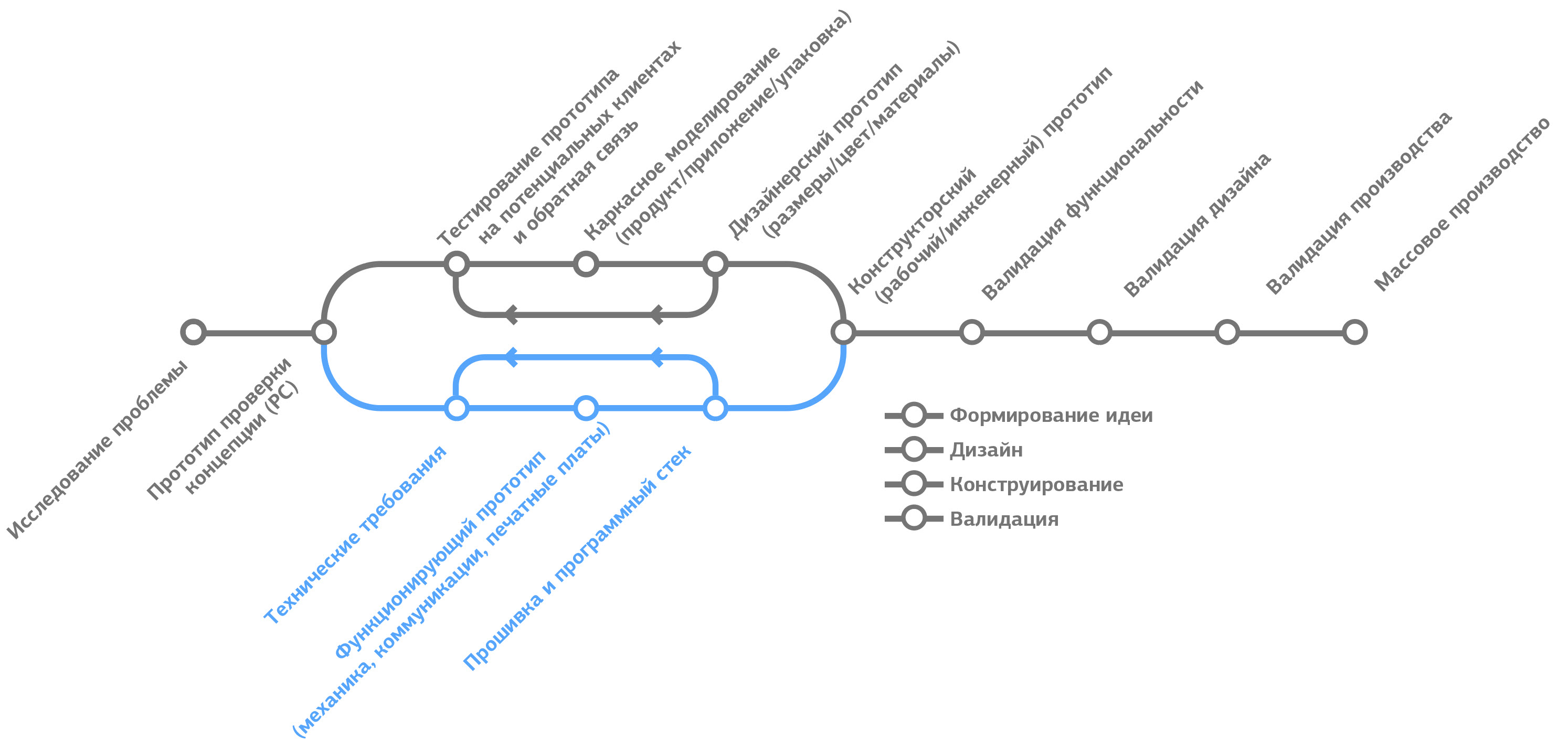
Figure 3.1 Product Design Steps
One of the best indicators of a well-designed product is the detail of technical documentation.
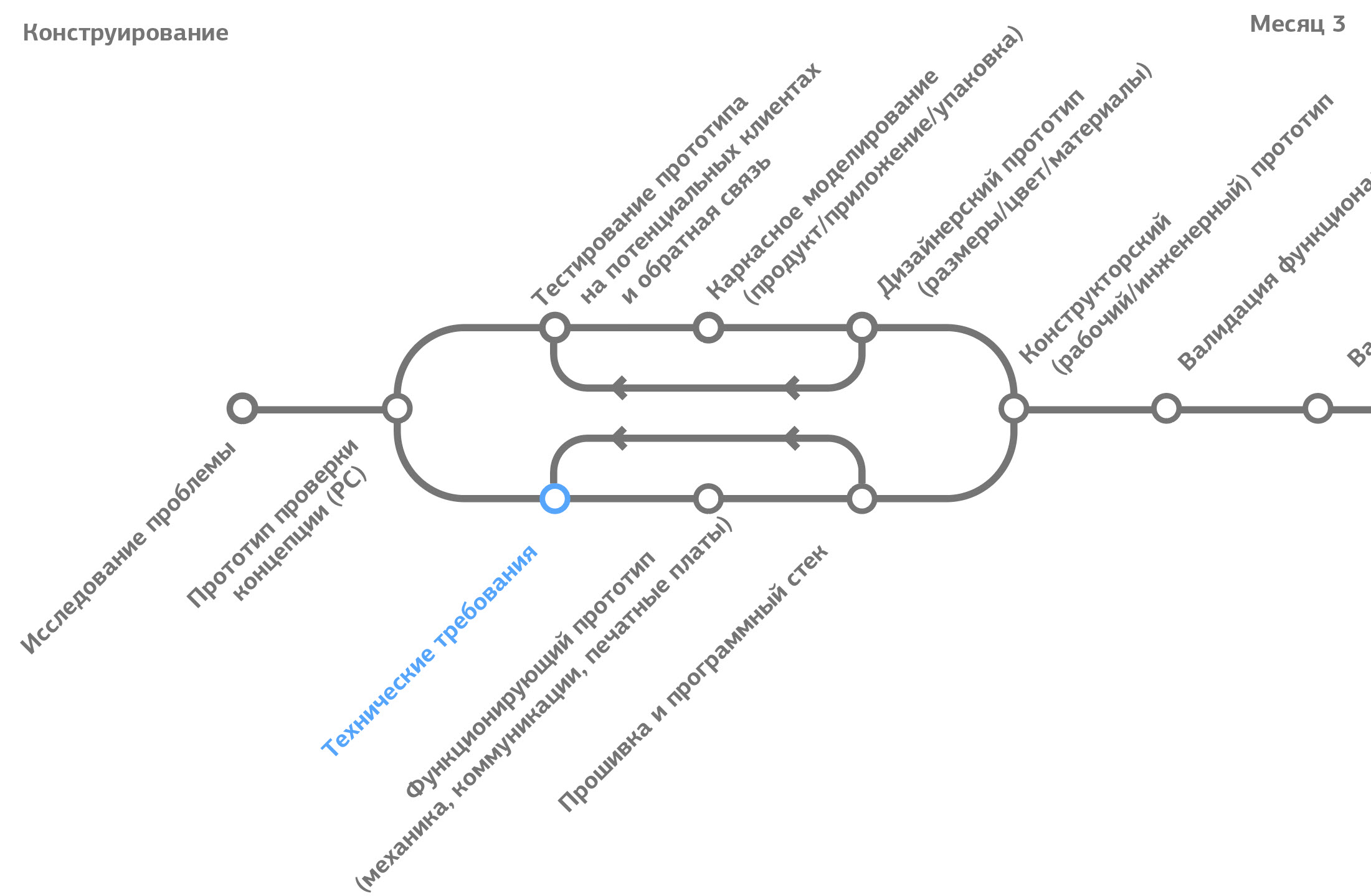
Figure 3.2. The place of formation of technical requirements in the product development cycle.
Technical requirements for the product (“spec”) are a critical document when creating any physical product. While many startups consider any type of documentation to be unnecessary and costly, I saw how companies lost months and tens of thousands of dollars due to the fact that they did not think through the technical requirements in detail.
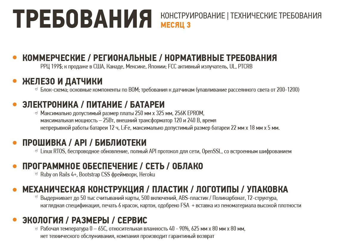
Figure 3.3 Categories of technical requirements
The requirements for most products can be identified by seven main areas:
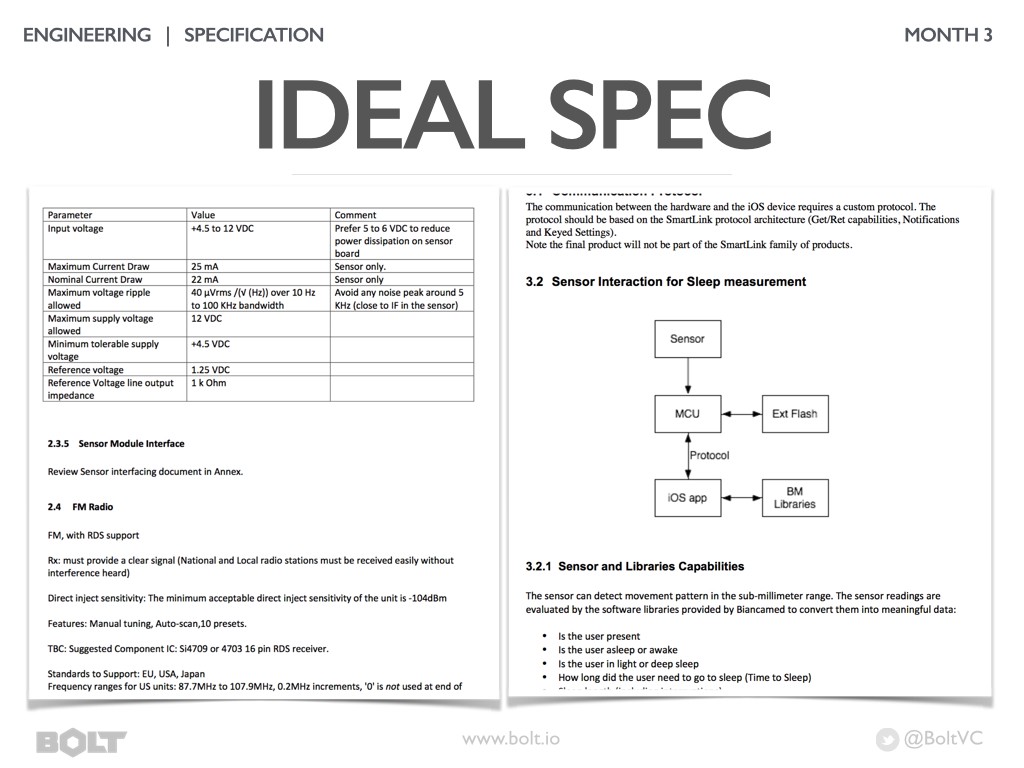
Figure 3.4 An example of generated technical requirements
Many large companies depend on mountains of documentation. These mountains of documents are usually repeatedly certified and full of tables with all possible details. While this is necessary for certain types of products, for most fast and flexible companies this approach is impractical.
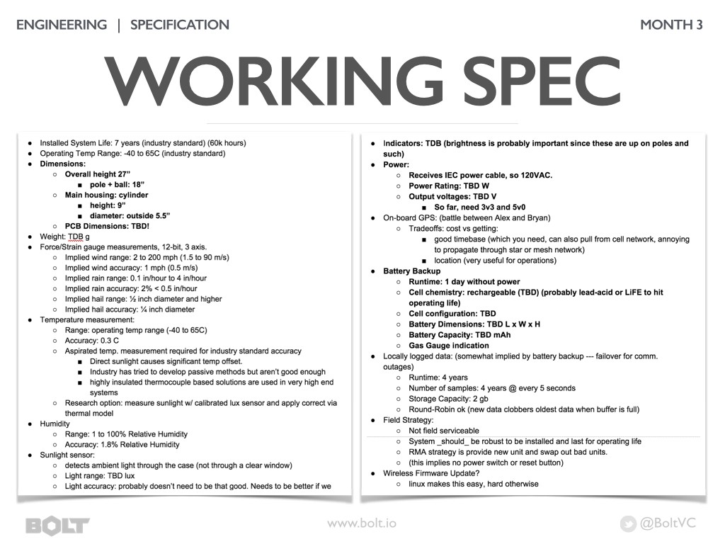
Figure 3.5 Example of a working specification of technical requirements
I find it more efficient to rely on a working spec. Such a document is usually shared online (for example, in Google Drive) and decomposed into several groups of requirements. Many companies are constantly updating this document as they refine their understanding of product requirements. It’s a good idea to think over all the possible requirements for the product and mark those that you don’t yet know but need to find out (in bold and “specify”).
When you enter enough information into the working specification, the time will come to answer each requirement with a technical solution. To do this, a prototype is created that may look different from the product, but works as a product and meets every specification requirement.
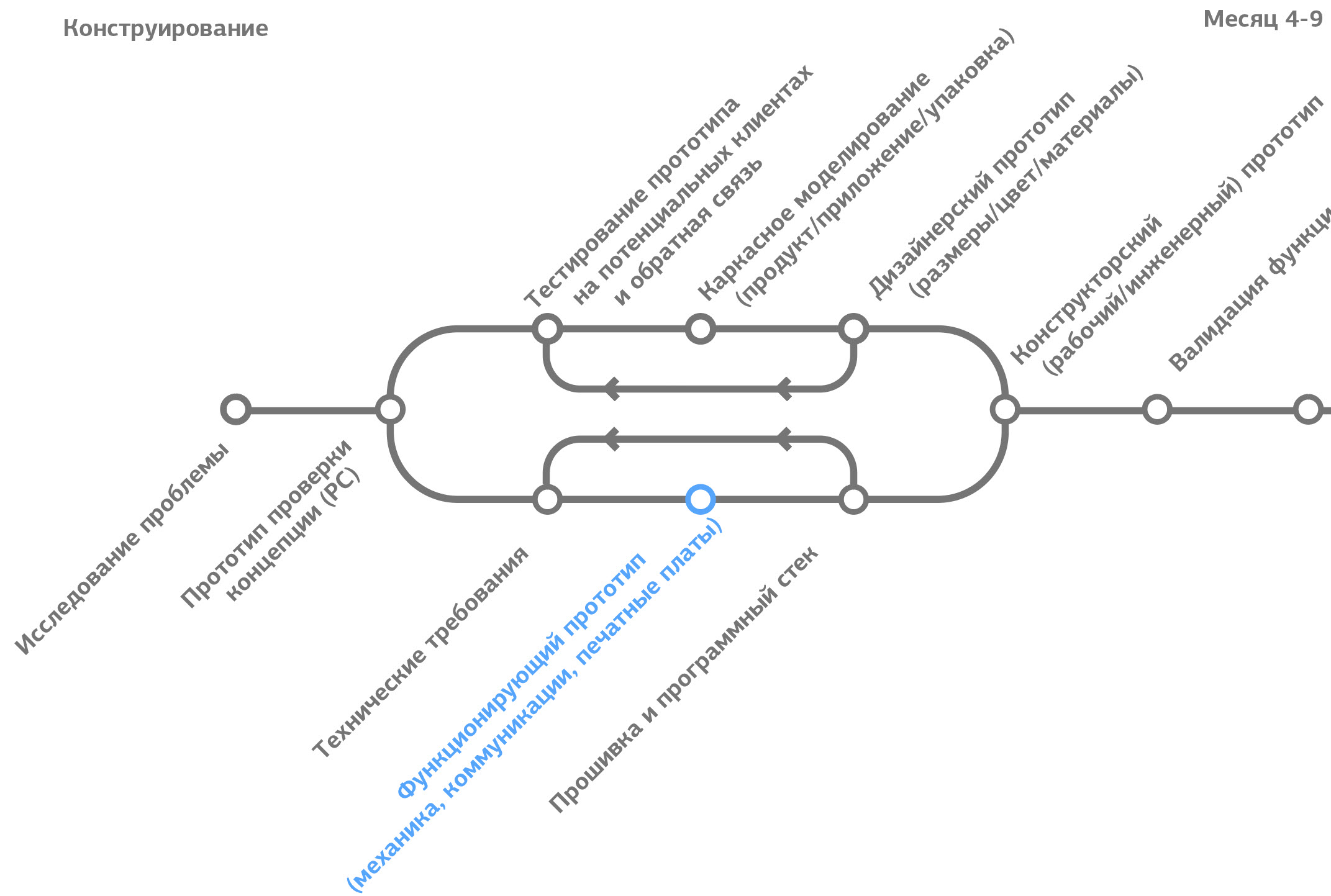
Figure 3.6. Place of creation of a functioning prototype in the product development cycle.
A functioning prototype is created to answer many questions that arose during the development of technical requirements: basic functions, selection of components, printed circuit boards, mechanics, product “feel” and assembly.
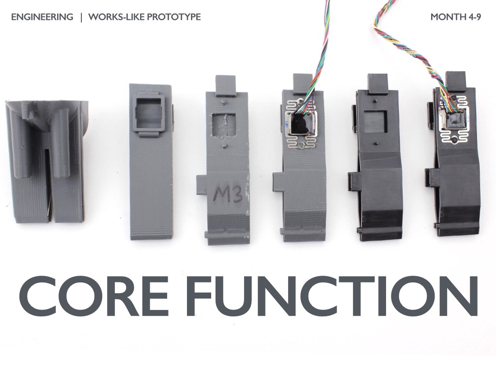
Figure 3.7. Iterations of the bracket design to provide basic functionality
Most products have a “core functionality”, which is crucial for the effective operation of the product. For DipJar, it is reading a card and conducting a transaction. In the photo above, you can see how the design of the bracket for the card reader changed and what design options were tested during development: (from left to right) from the coarsest bracket printed on a 3D printer to a prototype created using a mold. The reading head was also changed after determining the optimal mounting method for more stable reading of the magnetic strip of the card.
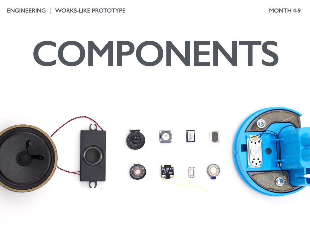
Figure 3.8 Component Selection: Speaker Selection Example
The choice of components can take several months of selection and qualification (testing) to ensure that they meet the requirements of functionality and reliability. In the photos above, there are several speaker modules that DipJar tested to optimize the combination of price, sound quality, reliability and availability / delivery speed.
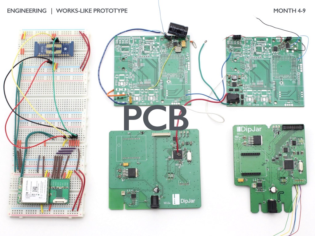
Figure 3.9 Evolution of the DipJar PCB
If your product has a PCB, it will take about 5-10 improvements before being launched into mass production. The board development process begins with the selection of components, then with the breadboard model (bread-boards, left), and then with the creation of a series of factory boards. The main DipJar board went through 6 iterations before being first launched into production by a contract manufacturer (CM, contract manufacturing).
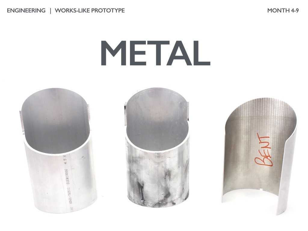
Figure 3.10 Working with the DipJar Enclosure
All components and boards must be protected. If metal is used in the case, working with it often requires a long development cycle. So, it took several months for the external DipJar case.
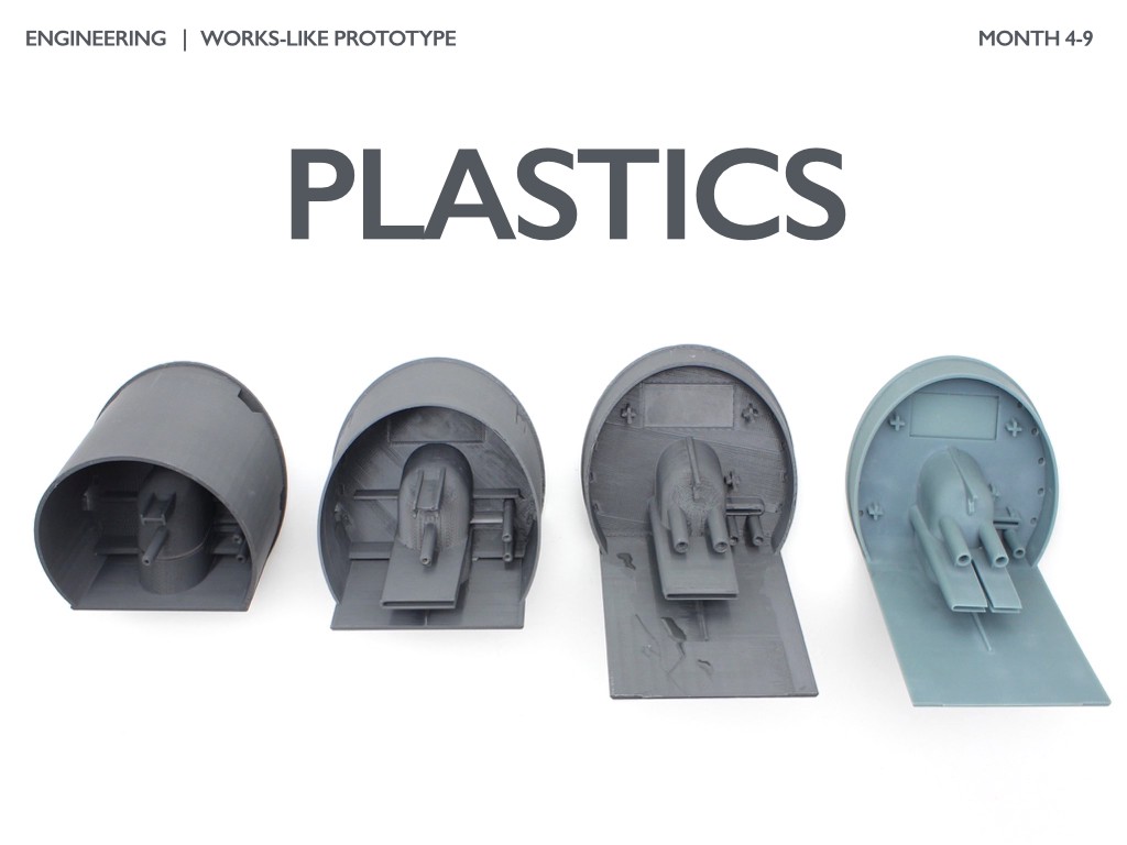
Figure 3.11 DipJar Plastic Parts
Almost every product I worked with had at least one plastic part. Molded plastic parts usually require 8-12 weeks of development and debugging, so you need to develop their design and construction as quickly as possible. The top panel of the DipJar has changed from being extremely difficult to cast on the left, to the final version on the right. Many parameters were optimized: previously design, wall thickness, circumference, bosses for fasteners, heat sinks, optics, processing texture, structural strength.
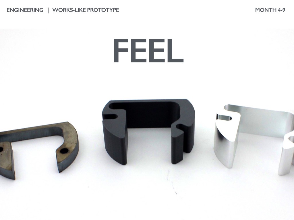
Figure 3.12 Weighting agents to form a product
feel. The “feel” of product is also very important. Many products use internal weights or thicken the walls to create a tactile sensation that matches the visual. DipJar has a relatively high center of gravity, and therefore its base is weighted with a laser-cut steel counterweight. In the second batch, to reduce the cost, the steel counterweight was replaced with aluminum.

Figure 3.13 Assembly
After selecting each component, designing the plastic parts and revising the boards, it is important to evaluate the product collection. In the early stages of a functioning prototype, an answer to the question of whether the product is assembled or not is enough. The closer the product is to mass production, the more important it is to focus on possible errors during assembly and on optimizing the cost and time of production. Assembly design also includes cable management planning, selection of adhesives, fasteners, leveling and positioning elements, clearances and part accessibility.
Almost all of the products Bolt invested in have both firmware and software. Unfortunately, this work usually should be done after the prototype is created, since the software depends on the operation of the hardware of the product.
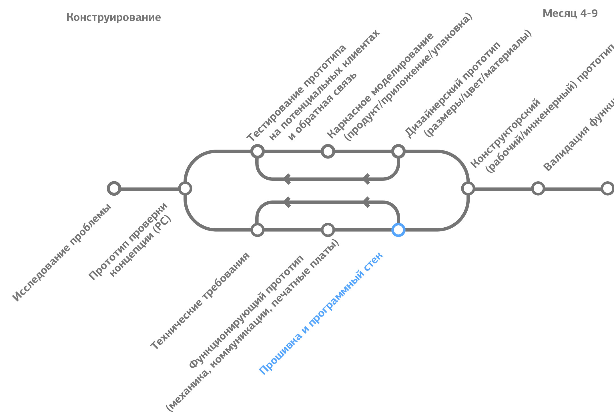
Figure 3.14 Location of firmware and software development in the product development cycle
Electrical engineers and embedded systems specialists use a variety of development approaches and sequences while working on firmware. The most common bottom-up approach.
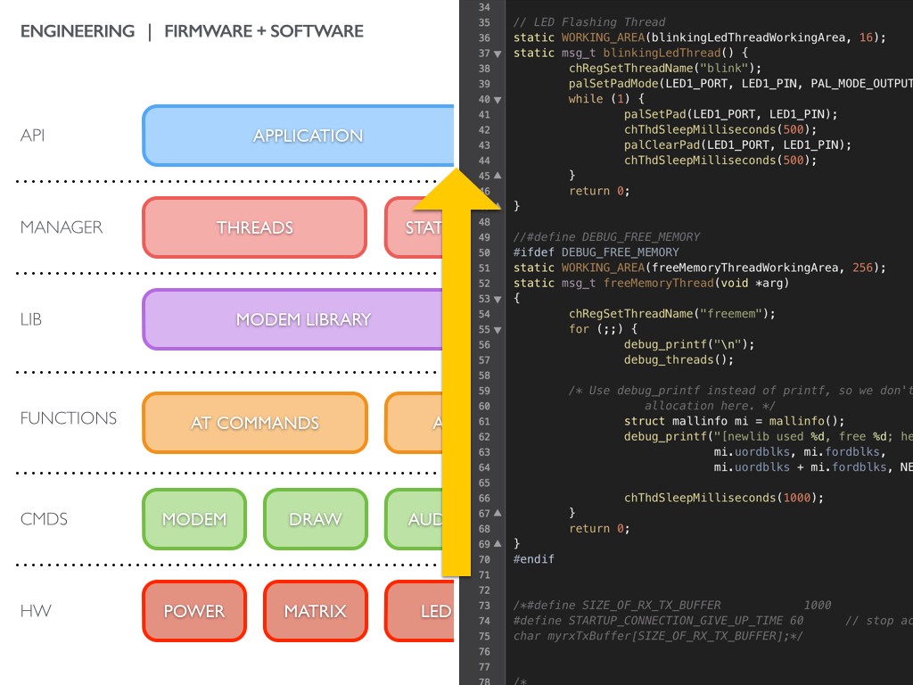
Figure 3.15 Firmware and software
The process starts at the lowest level (hardware) and goes up to the web software:
1. Hardware test- Creation of basic functions to verify the correct operation of the boards and the correctness of circuits. To find the main problems of the first revision, firmware upload, cyclically supplied power, blinking LEDs, power supply to communication tools, etc. are used.
2. Commands - checking all digital components (I2C, SPI, USB, serial buses, etc.) This is a basic functional test, which ensures that the components give correct responses.
3. Functions - packing each set of commands and logical sequences into user-defined functions. In the case of DipJar, the main function is to enter the amount in dollars and display it on the LED matrix.
4. The library - development of groups of functions that are together and depend on each other. For example, all display functions or all modem functions.
5. Control unit - many products work with multi-threaded data, and it can be difficult to achieve reliable operation of each stream. DipJar should read a credit card in a few seconds, that is, it has one data stream for cellular communication and one data stream for controlling the display matrix and audio feedback.
6. API / network - dedicated communication functions with various web services. Many products have two-way communication: as equipment communicates with the server, so the server communicates with the equipment. Building an organized, rational API guarantees the effectiveness and stability of communication.
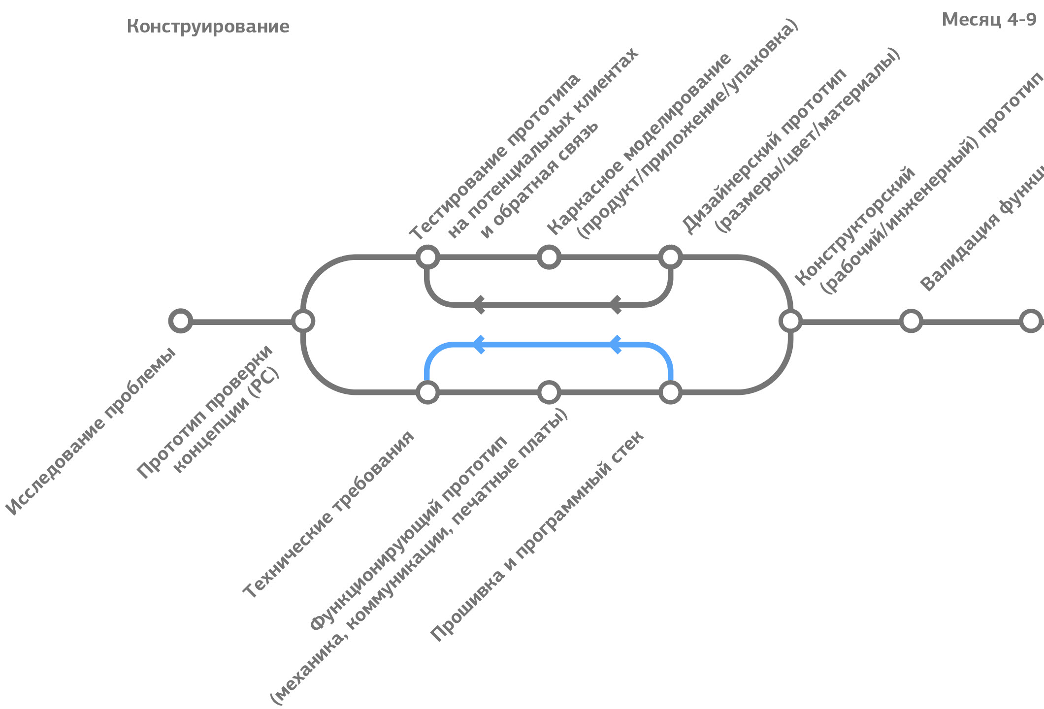
Figure 3.16 Iterations: working on errors and correcting flaws
Often, after the first assembly of a working prototype, a sea of flaws is determined. Sometimes the specification has incomplete / incorrect requirements, or the components may not meet the requirements of the specification. Usually 3-4 full-featured prototypes are created before moving on to the final development stage.
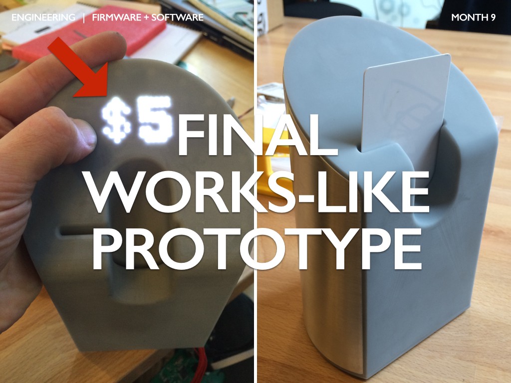
Figure 3.17 The final functioning prototype
As a result of the work, the prototype should confirm the feasibility of mass production of a reliable product. In the photo above - the final working prototype with still unfinished details (a red arrow indicates fuzzy LEDs, gray plastic, too large seams on a metal casing), but this product is already connected to the cellular network and has a reliable API for working with the card.
When a working prototype meets all the requirements of the specification, it’s time to get ready for production. Forward to Part 4: Validation
This is the third of four articles on the development of physical products. If you missed Part 1: Forming an idea , or Part 2: Design , it is worth reading them. You will soon be able to move on to Part 4: Validation. Posted by: Ben Einstein.Original twitter medium Translation execute commands fablaba FABINKA and project ARM .
Part 3: Design
Each step at the design stage (development of technical requirements, creation of a functioning prototype, programming of firmware / software) is needed to make sure that the product is functioning reliably and its production cost is optimal. The result of the engineering development process is a prototype that functions correctly, but does not yet have good user characteristics (UX) and is visually not too noble. Engineering and product design almost always go together.

Figure 3.1 Product Design Steps
Technical Specification
One of the best indicators of a well-designed product is the detail of technical documentation.

Figure 3.2. The place of formation of technical requirements in the product development cycle.
Technical requirements for the product (“spec”) are a critical document when creating any physical product. While many startups consider any type of documentation to be unnecessary and costly, I saw how companies lost months and tens of thousands of dollars due to the fact that they did not think through the technical requirements in detail.

Figure 3.3 Categories of technical requirements
The requirements for most products can be identified by seven main areas:
- Commercial and regulatory - countries of sale and recommended retail price (RRP, MSRP, manufacturer's suggested retail price), regulatory requirements, acceptable profit structure, product update schedule (end of life, End-of-life, EOL)
- Hardware and sensors - a complete diagram of the hardware system, a list of the main components according to the specification (BOM, bill of materials), requirements for sensors
- Electronics - board size (PCB, printed circuit boards), memory size, processor and communications requirements, size / lifetime / chemical composition of batteries
- Firmware and libraries - operating system or embedded environment used by firmware, API specifications, requirements for external libraries
- Software and network - software stack and development environment, server infrastructure requirements, SCM plans (Software Configuration Management), error handling
- Durability and packaging - requirements for the service life , endurance of various subsystems, packaging requirements
- Ecology and operation - operating temperatures and humidity, description of operational reliability, settings and tolerances, requirements for return / replacement processes, requirements for customer support and spare parts

Figure 3.4 An example of generated technical requirements
Many large companies depend on mountains of documentation. These mountains of documents are usually repeatedly certified and full of tables with all possible details. While this is necessary for certain types of products, for most fast and flexible companies this approach is impractical.

Figure 3.5 Example of a working specification of technical requirements
I find it more efficient to rely on a working spec. Such a document is usually shared online (for example, in Google Drive) and decomposed into several groups of requirements. Many companies are constantly updating this document as they refine their understanding of product requirements. It’s a good idea to think over all the possible requirements for the product and mark those that you don’t yet know but need to find out (in bold and “specify”).
Functioning prototype
When you enter enough information into the working specification, the time will come to answer each requirement with a technical solution. To do this, a prototype is created that may look different from the product, but works as a product and meets every specification requirement.

Figure 3.6. Place of creation of a functioning prototype in the product development cycle.
A functioning prototype is created to answer many questions that arose during the development of technical requirements: basic functions, selection of components, printed circuit boards, mechanics, product “feel” and assembly.

Figure 3.7. Iterations of the bracket design to provide basic functionality
Most products have a “core functionality”, which is crucial for the effective operation of the product. For DipJar, it is reading a card and conducting a transaction. In the photo above, you can see how the design of the bracket for the card reader changed and what design options were tested during development: (from left to right) from the coarsest bracket printed on a 3D printer to a prototype created using a mold. The reading head was also changed after determining the optimal mounting method for more stable reading of the magnetic strip of the card.

Figure 3.8 Component Selection: Speaker Selection Example
The choice of components can take several months of selection and qualification (testing) to ensure that they meet the requirements of functionality and reliability. In the photos above, there are several speaker modules that DipJar tested to optimize the combination of price, sound quality, reliability and availability / delivery speed.

Figure 3.9 Evolution of the DipJar PCB
If your product has a PCB, it will take about 5-10 improvements before being launched into mass production. The board development process begins with the selection of components, then with the breadboard model (bread-boards, left), and then with the creation of a series of factory boards. The main DipJar board went through 6 iterations before being first launched into production by a contract manufacturer (CM, contract manufacturing).

Figure 3.10 Working with the DipJar Enclosure
All components and boards must be protected. If metal is used in the case, working with it often requires a long development cycle. So, it took several months for the external DipJar case.

Figure 3.11 DipJar Plastic Parts
Almost every product I worked with had at least one plastic part. Molded plastic parts usually require 8-12 weeks of development and debugging, so you need to develop their design and construction as quickly as possible. The top panel of the DipJar has changed from being extremely difficult to cast on the left, to the final version on the right. Many parameters were optimized: previously design, wall thickness, circumference, bosses for fasteners, heat sinks, optics, processing texture, structural strength.

Figure 3.12 Weighting agents to form a product
feel. The “feel” of product is also very important. Many products use internal weights or thicken the walls to create a tactile sensation that matches the visual. DipJar has a relatively high center of gravity, and therefore its base is weighted with a laser-cut steel counterweight. In the second batch, to reduce the cost, the steel counterweight was replaced with aluminum.

Figure 3.13 Assembly
After selecting each component, designing the plastic parts and revising the boards, it is important to evaluate the product collection. In the early stages of a functioning prototype, an answer to the question of whether the product is assembled or not is enough. The closer the product is to mass production, the more important it is to focus on possible errors during assembly and on optimizing the cost and time of production. Assembly design also includes cable management planning, selection of adhesives, fasteners, leveling and positioning elements, clearances and part accessibility.
Firmware and software (Firmware and Software)
Almost all of the products Bolt invested in have both firmware and software. Unfortunately, this work usually should be done after the prototype is created, since the software depends on the operation of the hardware of the product.

Figure 3.14 Location of firmware and software development in the product development cycle
Electrical engineers and embedded systems specialists use a variety of development approaches and sequences while working on firmware. The most common bottom-up approach.

Figure 3.15 Firmware and software
The process starts at the lowest level (hardware) and goes up to the web software:
1. Hardware test- Creation of basic functions to verify the correct operation of the boards and the correctness of circuits. To find the main problems of the first revision, firmware upload, cyclically supplied power, blinking LEDs, power supply to communication tools, etc. are used.
2. Commands - checking all digital components (I2C, SPI, USB, serial buses, etc.) This is a basic functional test, which ensures that the components give correct responses.
3. Functions - packing each set of commands and logical sequences into user-defined functions. In the case of DipJar, the main function is to enter the amount in dollars and display it on the LED matrix.
4. The library - development of groups of functions that are together and depend on each other. For example, all display functions or all modem functions.
5. Control unit - many products work with multi-threaded data, and it can be difficult to achieve reliable operation of each stream. DipJar should read a credit card in a few seconds, that is, it has one data stream for cellular communication and one data stream for controlling the display matrix and audio feedback.
6. API / network - dedicated communication functions with various web services. Many products have two-way communication: as equipment communicates with the server, so the server communicates with the equipment. Building an organized, rational API guarantees the effectiveness and stability of communication.

Figure 3.16 Iterations: working on errors and correcting flaws
Often, after the first assembly of a working prototype, a sea of flaws is determined. Sometimes the specification has incomplete / incorrect requirements, or the components may not meet the requirements of the specification. Usually 3-4 full-featured prototypes are created before moving on to the final development stage.

Figure 3.17 The final functioning prototype
As a result of the work, the prototype should confirm the feasibility of mass production of a reliable product. In the photo above - the final working prototype with still unfinished details (a red arrow indicates fuzzy LEDs, gray plastic, too large seams on a metal casing), but this product is already connected to the cellular network and has a reliable API for working with the card.
When a working prototype meets all the requirements of the specification, it’s time to get ready for production. Forward to Part 4: Validation
This is the third of four articles on the development of physical products. If you missed Part 1: Forming an idea , or Part 2: Design , it is worth reading them. You will soon be able to move on to Part 4: Validation. Posted by: Ben Einstein.Original twitter medium Translation execute commands fablaba FABINKA and project ARM .
