Insulin pumps, tamper-evident microchips, and software-defined radio
- Transfer
Reverse Engineering of an Insulin Pump for DIY Therapy
About three years ago I heard about a website offering a reward for being very close to my heart: reverse engineering communications with an insulin pump. I already helped create a system for my daughter called Loop , with a Medtronic pump, for which I reverse engineer communications (most of the main Medtronic communication protocol was decoded by Ben West using the Carelink USB device, and I found out the radio frequencies and did some extra work on protocol). But the Medtronic pump needed to be shut off during gymnastics for several hours. The tubeless design of this Omnipod pump seemed interesting to me, and I had all the tools to work.
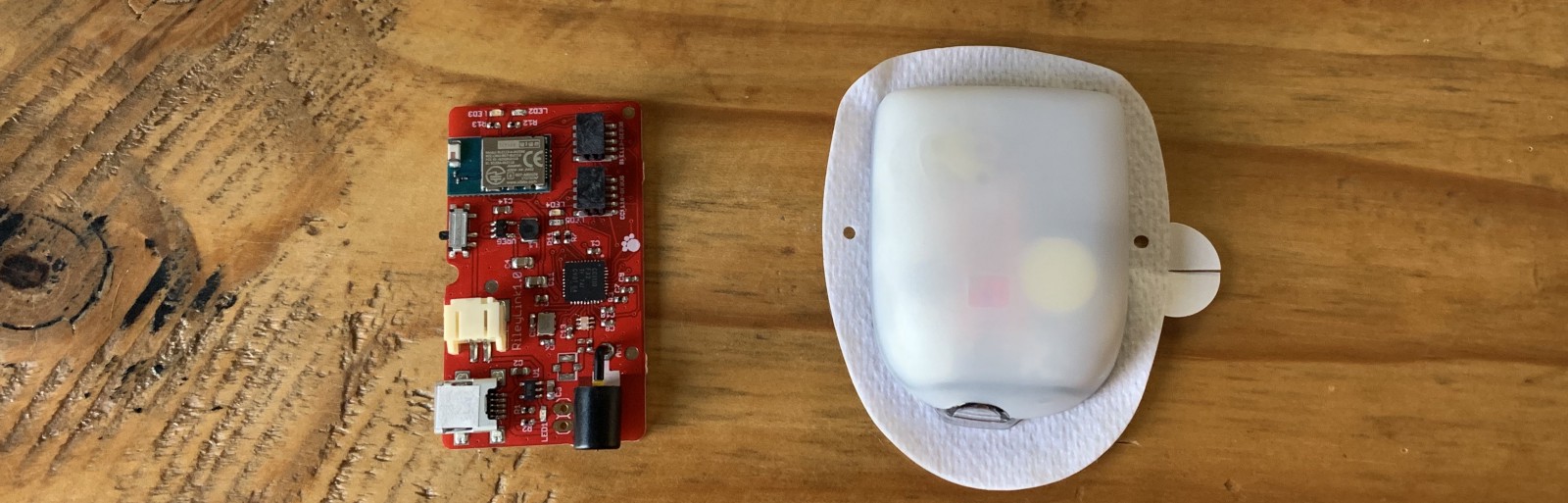
The Omnipod system consists of a small, single-use pump called a module (pod) and a control unit (PDM).
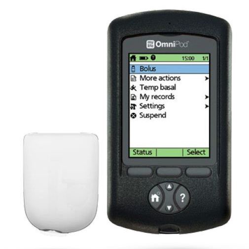
Since the PDM communicates with the module by radio, and the module does not have a built-in interface, this means that it is fully radio controlled. There is a possibility of full integration with Loop, using only RileyLink or its modified version.
James Wedding appointed a reward, and it attracted a lot of attention, and then the right people who helped in the work.
SDR is a terrific tool . He makes visible the hidden world of radio. There are a variety of types of messages that are constantly streaming on the air, and these tools allow you to poke around, view messages, and after some work - decode the small flashes that you see there. If you are looking for messages from a specific device, you need to know in which area to start the search. This is where FCC public documents come in handy.
The FCC documentation for PDM, RBV-019 , says the device transmits in the 433 MHz band. After configuring the SDR software to listen in the 433 MHz range, when the status is received from PDM, the following signals appear:
As I finally found out, these two bright lines indicate a certain type of modulation, calledfrequency shift keying , or FSK. This means that the signal frequency varies depending on the transmitted information. Bit 1 is sent as a higher frequency (upper line), and 0 is sent with a slightly lower frequency (lower line). Using the inspectrum tool , we can analyze the data to more clearly recognize 1 and 0. Here is a greatly enlarged view of the first message:

I wrote a Python script to extract these bits so that we can look at them as whole packets.
It turns out that this repeating pattern is part of the preamble.. To save energy, receivers often go into sleep mode and wake up periodically to check the signal. The transmitter sends the preamble long enough for the receiver to catch it during one of the short listening periods. When the receiver hears the preamble, it wakes up until real data appears.
You need to go through another layer before you get the actual batch data. You cannot send your data over the radio in exactly the same way as the original bits, because the receiver uses transitions to synchronize in time when to wait for the next bit. If you have a long set of zeros or ones, then the receiver may go out of sync. Therefore, radio communications typically use encoding to verify that there are enough transitions. In communications Omnipod uses the so-calledManchester coding . Each bit is encoded in two bits. 1 is encoded as 10, and 0 is encoded as 01.
All this took a long time to figure out, and there were many theories on the openomni channel in Slack , as we tried to repeat the original bits. Mark Brighton , Dan Caron, and @larsonlr have achieved some success using RFCat and Ti Stick to capture packets. Evarist Kurgio eventually wrote a tool called rtlomni , he uses the rtl-sdr USB receiver to listen to packets and decode them, which turned out to be very convenient and more reliable than methods based on TI Stick.
Having received the actual bits, we began to study the structure of the package. Based on what bits changed between different modules and different teams, we made up a structure that looks like this:

Radio is far from an ideal transmission medium. There are many different sources of interference that make the receiver hear 1 when 0 is sent, and vice versa. It is important to know when this happened, so most protocols use a checksum, often called CRC. The receiver calculates the CRC as data is received, and the last byte of the packet includes the CRC calculated by the transmitter. If they do not match, the receiver discards the packet and waits for retransmission.
The Omnipod protocol used the standard 8-bit CRC. When we found him, we decided that we were very close to understanding the messages. How little we knew ...
Some messages are too large to fit in one package, so they are split into several packages. We started to piece together the message format and noticed another set of bits at the end of each message, which looked like a 16-bit CRC. But it was strange: 5 out of 16 bits were never set. We tried many different methods to figure out how this is encoded, but nothing worked.
This was the first big problem: we could continue to work on other bits in the messages, but it will not help much to understand what is being sent, and we will not be able to generate new packets ourselves, so progress slowed down.
Several months passed almost to no avail. Finally, in the winter of 2016, a member of the group under the nickname @lorelaireported that she successfully copied the firmware from a larger ARM chip to PDM and began the tedious disassembly process: accepting the CPU instructions and turning them into human-readable code with semantic variables and function names. She did an amazing job finding out the various methods that were used to transmit data.
I looked at one of the untitled routines and noticed that it looked like a standard implementation of CRC calculation from a table. And the table had values for the standard 16-bit CRC. I wrote my own implementation on tables, and it was tested like a regular CRC. Then I carefully looked at how the function was written. A normal CRC implementation looks like this:
Their implementation looked like this ::
Notice the difference? What was supposed to be a bitwise left shift operator was somehow encoded as a right shift. This is mistake; There is no reason to cripple your own CRC algorithm, as this makes it difficult to identify corrupted messages.
We are back in operation! And they resumed work on decoding messages, recording sessions from PDM for the delivery of boluses [drugs], temporary bases [Temporary Basal Rate determines an increase or decrease in insulin delivery - approx. lane], suspension of filing, etc.
All insulin delivery teams had a 4-byte piece of data at the beginning of the message, which looked like some form of cryptography. Again, we tried many different ways of interpreting and analyzing it in the context of the messages in which it was sent, but it was not CRC (sometimes we saw the same 4 bytes even in different messages). And sometimes we saw the picture repeat itself. It looked, perhaps, as part of a protocol to prevent data reproduction. In other protocols, a similar function is called nonce .
One of the options that we considered was recording a message base for playing back given commands. Even if the address of each module was different, now we knew how to generate a CRC, so that we could take the previous copy of the command, put the new address on the message and recount the CRC. Only this nonce prevented us from using this strategy. Regardless of the command, the module only accepted the next nonce in the sequence, and we did not know how to generate the next nonce.
But! After all, we have a decompiled PDM firmware, we can just look there! So, we studied the PDM firmware, tracked the generation of messages in the code and found where these four bytes should be. But instead of a method that computes some cryptographic nonce, we just found four characters
There was another chip on the PDM, closer to the radio. It was the same chip that was used in the modules, with the identifier SC9S08ER48, which was not documented on the Internet. It was probably made to order for the Insulet. Maybe we can remove the firmware from this chip. Unfortunately, the chip was blocked, which prevented the copying of the firmware.
Work slowed down again ... it was like a real dead end. We put all our mental efforts into this nonce, and we did not have any good leads in the math behind it. And the ER48 chip, which (possibly) kept secrets, was blocked, and it’s hard to find any public information that would help to crack it.
Trying to understand ER48, some members of the Slack community suggested taking x-rays. It was really cool, but, unfortunately, did not open any new opportunities.
General shot

Detailed shot
Dan Caron decided to turn to a researcher, Dr. Sergey Skorobogatov from the University of Cambridge in the UK. Dan read that he has experience extracting code from locked chips, and convinced him to take a look at our problem. Dr. Skorobogatov conducted research in the field of using SEM (scanning electron microscope) for reverse engineering of microcircuits. He suggested that it is possible, but it will be expensive, require expensive equipment and does not guarantee a result. Joe Moran, who recently started using Loop after we met at the Nightscout hackathon in the fall of 2016, agreed to help with the project. He agreed with a Silicon Valley company, Nanolab Technologies, to open and photograph the chips, and also kindly funded the work of Nanolab and Dr. Skorobogatov (as well as his personal modules).
Dr. Skorobogatov asked Nanolab to apply various imaging techniques to find out if it is possible to crack the protection with known non-invasive or semi-invasive methods. As a result, many images appeared, some of them very beautiful. These are optical microscopic images of a silicon matrix.
General view of the microcircuit under an optical microscope
General view of the microcircuit under an optical microscope
Pictures were also taken of specific areas of the matrix using a scanning electron microscope. With different voltages, different surface preparation and different equipment.

SEM image of flash cells. Shows no data
Unfortunately, none of these images showed the actual contents of the flash memory.
Dr. Skorobogatov had one last method, which can be used only in case of failure. This was a patented method, the use of which had to obtain the permission of the university. Dr. Skorobogatov did the initial test and confirmed that he was able to read data on this chip. But before continuing, it was necessary to sign the NDA, and therefore negotiations were held on who would receive the contents of the extracted firmware.
Ultimately, the NDA signed the Nightscout foundation, and took responsibility for preventing the unauthorized disclosure of memory extraction methods and results.
The result of this agreement and work was an incredible article.written by Dr. Sergei Skorobogatov, as well as the firmware code. From the first time there were quite a few errors in the code, but this was enough to get started. At the Nightscout Spring Hackathon, Joe turned to the guys if anyone would like to do disassembly. No one raised his hands. Turning processor instructions into something understandable is painstaking work, and very few people know how to do it. I tried to delve into assembler using the CPU documentation, but I achieved very little and was disappointed. Others optimistically asked for the firmware code with expectations of rapid progress, then realized the scale and complexity of the task - and quietly fell off.
SC908 instruction disassembly example
It turns out that Joe also had extensive experience working with assembler, and he began to carry out this difficult task. In July, Dr. Skorobogatov completed a second memory extraction operation with much fewer errors. During the summer, Joe Moran worked tirelessly to display a huge number of processor instructions and gradually integrate them into the overall picture of the module pseudocode.
In the end, Ken Shirriff , an expert in hardware reverse engineering, joined us , and he greatly accelerated the process. Together, Joe and Ken ended up translating enough code to find a function that encodes nonce. This happened in September 2017.

We have updated the Python scripts openomni , but now it's time to focus on RileyLink + iOS, so I started working on OmniKit and firmware updates for RileyLink. I believed that we had the basics of the protocol, and the rest was just details. Again, completely underestimating how much is yet to come.
I had to write a new firmware that handles modulation and coding of the module. I also had to rewrite how two chips on RL talk to each other in order to process zeros, since in Medtronic zeros were the special end of the packet marker. Much of Loop had to be redesigned to support multiple pumps, as well as new interfaces to support pairing, deactivation, and error handling. Fortunately, Nate Wrecliftlaid a solid foundation at Loop to make it all possible.
Meanwhile, work continued on understanding the format of the teams. Everything was carefully documented on the openomni wiki , the most comprehensive documentation of the protocol. Joe, Evarist and Elke Jäger have done a really great job over time in decoding messages and updating pages. Various Slack channel members have contributed to the capture of PDM packets and the module to help the overall decoding efforts.
Decoding was a fun job, with a lot of small victories, as each component of each team decrypts, and I really liked working on this part, gradually adding code to Loop. In April 2018, I shared at Slack that I did "primary cannulation paired via iPhone + RL according to the programmed basal schedule, and then 5 units became ill."
RL 2.0 firmware was completed in July 2018, and new deliveries have already gone with it. It was hoped that these boards could be used with Loop and Omnipod, but the existing 915 MHz antenna was too bad to work effectively at 433 MHz.
Decoding and implementation have progressed significantly over the summer, and Loop is gradually approaching performance. Joe did the amazing thing by giving me funding so I quit my day job and focus on this project, and eventually I joined the wonderful Tidepool team. Of course, in the field of DIY and the legislative regulation of medical equipment there were more events that I will not cover, but it was a very interesting summer!
When more functions appeared in the driver, I connected it to Loop, turning on the ability to automatically configure delivery on time. At this stage, “flashy” modules were often obtained when some of the internal module checks found a problem and he stopped delivering insulin.
But this seemed to be a solvable problem, as we continued to find small discrepancies in the Loop packages and the original PDM when sending commands manually, and I assumed that if we fix them all, the “screams” will stop.
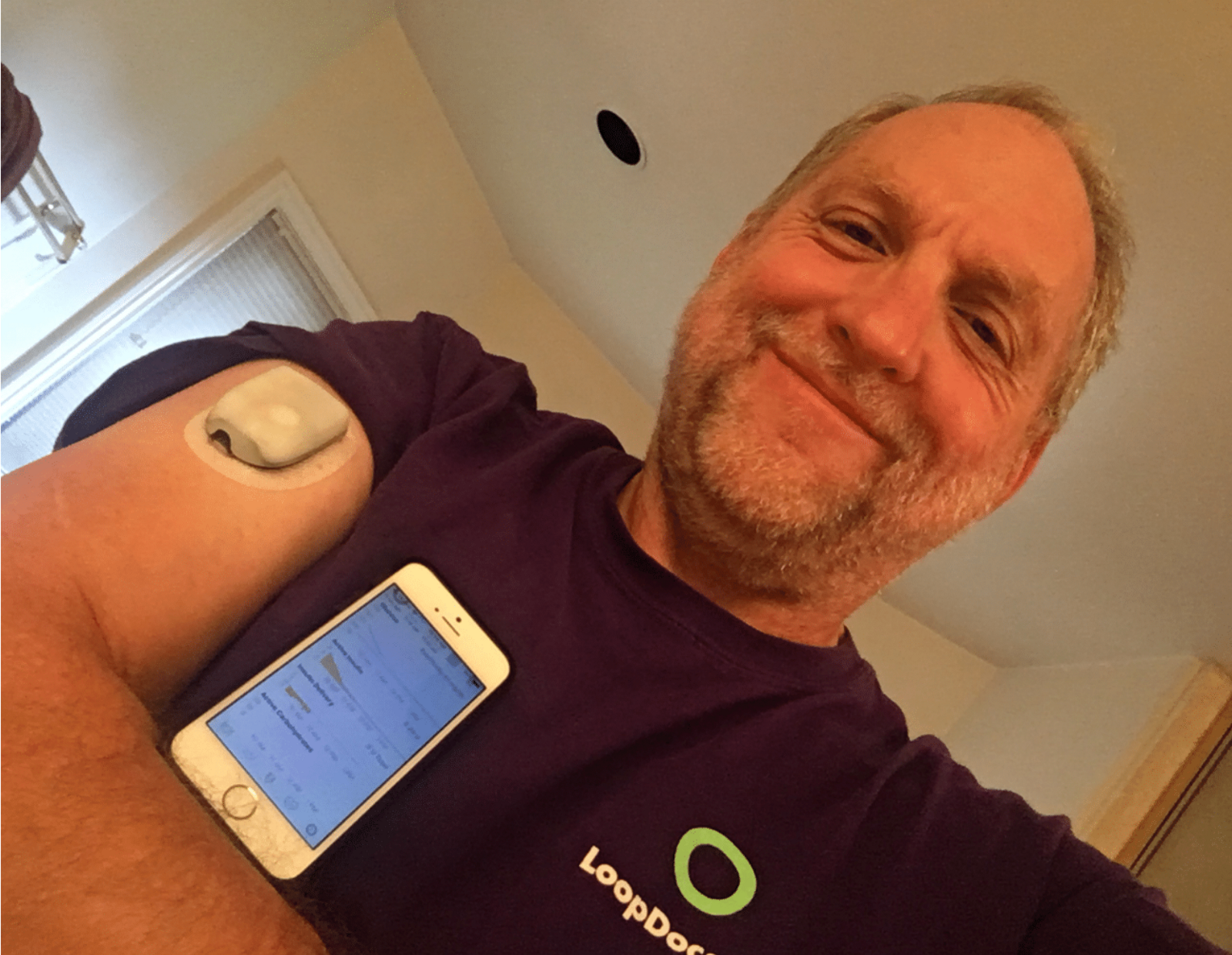
On October 3, 2018, Joe donned the Loop managed module and became the first Loop Omnipod user, although he did not tell me right away because he knew that I would be worried. When he told me, I was still worried. We saw how the module worked and understood the functionality, and the basic algorithm was tested for a long time, but still ...
A month later, at the Nightscout hackathon in November 2018, several more adventurers decided to try it for themselves, and also became part of a small a closed testing group that will grow to more than 30 people before the code is published.
Unfortunately, we still encountered module “screams”, often occurring before the completion of the full three days of use, and we carefully compared Loop commands with PDM samples. In this process, Elke was especially useful: he wrote a script for automatically checking commands with original versions. I began to worry that the intermittent operation of the modules was caused by increased battery requirements for communications every five minutes.

The taps of the power supply voltage regulator in the module, drilled through the plastic of the rear panel, are super-glued.
Therefore, I began to measure the power supply voltage of the module using Arduino, write data and save them in a local database for visualization. I compared PDM and Loop.
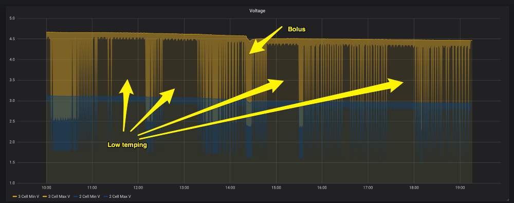
Long-term change in module supply voltage
Unfortunately, this also turned out to be a dead end; using PDM and injecting a large amount of insulin, I could bring the module to a lower voltage than during the entire life of the Loop module, and could not make the module “scream”. It seemed that stress was not a problem, there must be something else.

RileyLinks with 955 MHz (left) and 433 MHz coil antennas (right)
At some point I noticed that if the exchange of messages with the module failed, the module sometimes continued trying to end the exchange by resending packets again and again. The testers logs also showed a lot of glitches, so I started experimenting with antennas. Both problems should be related to the quality of communication. I planned to try different antennas and ordered them in different places on the Internet, but I did not have time to test them until this became a priority.
I had several 433 MHz flexible antennas that can be attached to the inside of the RL enclosure. They often show better performance in some scenarios, but not in others; too unreliable. When I got to the reel, it showed good performance very consistently and on very amazing ranges. Time to make a new case for RileyLink.
With a new antenna and some optimizations that reduced messaging while still making adjustments every 5 minutes, screams became very rare. Probably comparable to the usual use of modules with PDM. Over the past 7,500 hours of real-time testing, 94% of the modules completed without fail.
The testing group slowly grew: new users constantly joined the system, who with a fresh look could evaluate which parts look confusing. These testers put up with a lot of flashy modules and made a very big contribution to improving Loop's performance with Omnipod. Basically, they sent problem reports and work logs.
These reports have a log of messages that can be analyzed using a tool made by Elke. It gives an idea if we get any distorted commands, and also allows you to collect statistics on certain parts of the interaction of Loop with modules.
Marion BarkerJoined the testing group and added special reporting and additional statistics on testing progress - and we were able to use its statistics of successful modules against failures to have an idea of progress at a high level.
In the end, Katie DiSimone joined the testing group . She began a major restructuring of loopdocs.org with documentation on using Loop with multiple devices. The wait for the version of Loop that worked with Omnipod was incredibly high, and without good documentation it was clear that we would be overwhelmed with the same questions.
Integration with Omnipod required a rethinking of some of the interface elements and the addition of new controls. The module does not report the battery, and the user can do little with a low charge if this happens, so displaying the battery level widget does not make sense. In addition, without a user interface on the pump, the user should be able to quickly cancel the bolus. The tank icon depicted the Medtronic tank, so we wanted to remake it. Thanks to Paul Forgione for developing the logo of the module, which now shows the level of the tank.

Thanks to all the people who helped us go this long way so that we realize the goal that we set a long time ago. I know that I did not mention all involved and not all events. This is not possible in one article, and I have only personal experience. It is hard to imagine how many hours it took. If you add them all together, I’m sure it’s a shocking figure. Not to mention the work on creating the Omnipod itself, which, it seems to me, overshadows all these efforts. So thank you all. In addition, many of these hours would otherwise have been spent with families. I really appreciate the understanding of my wife and children because of the time I spent on it, and I want to thank them too.
I should mention Joachim Ornstedt as one of the contributors to openomni decoding, as well as the creator of probably the first integration with omnipod. He built a device that used optical character recognition (OCR) to extract data from the PDM, and connected the number buttons to the physical PDM through another microcontroller. This approach is difficult to scale, but it is very smart and bypasses many of the problems that we had to deal with a solution based on RE. I really admire how he dealt with the problem and set up work for a tiny fraction of the time it took to get the device to work with Loop.
About three years ago I heard about a website offering a reward for being very close to my heart: reverse engineering communications with an insulin pump. I already helped create a system for my daughter called Loop , with a Medtronic pump, for which I reverse engineer communications (most of the main Medtronic communication protocol was decoded by Ben West using the Carelink USB device, and I found out the radio frequencies and did some extra work on protocol). But the Medtronic pump needed to be shut off during gymnastics for several hours. The tubeless design of this Omnipod pump seemed interesting to me, and I had all the tools to work.
The Omnipod system consists of a small, single-use pump called a module (pod) and a control unit (PDM).
Since the PDM communicates with the module by radio, and the module does not have a built-in interface, this means that it is fully radio controlled. There is a possibility of full integration with Loop, using only RileyLink or its modified version.
James Wedding appointed a reward, and it attracted a lot of attention, and then the right people who helped in the work.
Software Defined Radio
SDR is a terrific tool . He makes visible the hidden world of radio. There are a variety of types of messages that are constantly streaming on the air, and these tools allow you to poke around, view messages, and after some work - decode the small flashes that you see there. If you are looking for messages from a specific device, you need to know in which area to start the search. This is where FCC public documents come in handy.
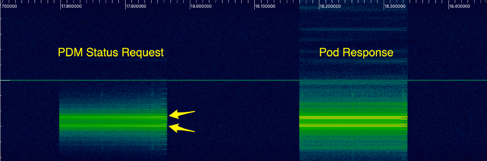
The FCC documentation for PDM, RBV-019 , says the device transmits in the 433 MHz band. After configuring the SDR software to listen in the 433 MHz range, when the status is received from PDM, the following signals appear:
As I finally found out, these two bright lines indicate a certain type of modulation, calledfrequency shift keying , or FSK. This means that the signal frequency varies depending on the transmitted information. Bit 1 is sent as a higher frequency (upper line), and 0 is sent with a slightly lower frequency (lower line). Using the inspectrum tool , we can analyze the data to more clearly recognize 1 and 0. Here is a greatly enlarged view of the first message:
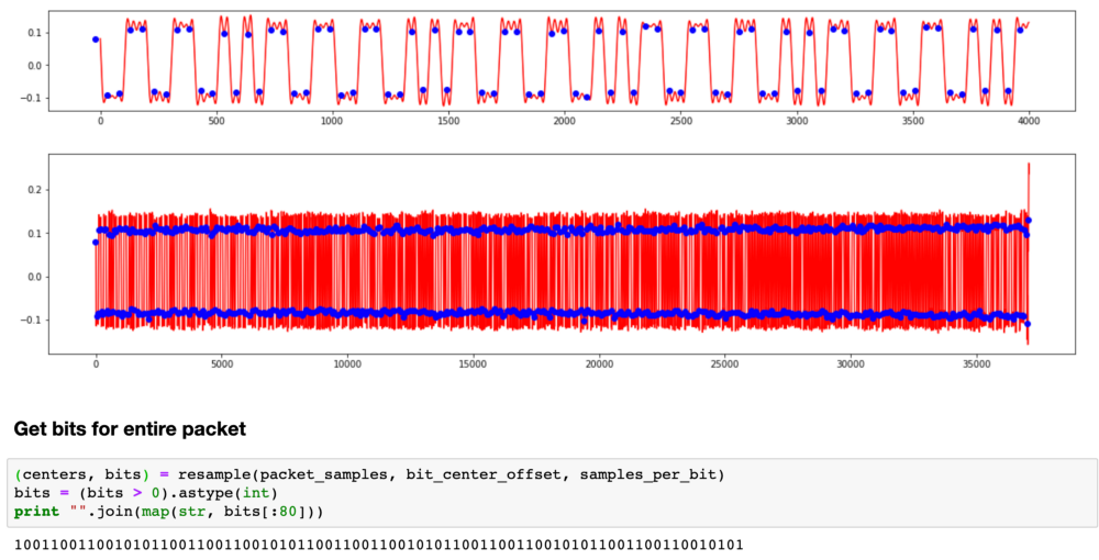
I wrote a Python script to extract these bits so that we can look at them as whole packets.
It turns out that this repeating pattern is part of the preamble.. To save energy, receivers often go into sleep mode and wake up periodically to check the signal. The transmitter sends the preamble long enough for the receiver to catch it during one of the short listening periods. When the receiver hears the preamble, it wakes up until real data appears.
You need to go through another layer before you get the actual batch data. You cannot send your data over the radio in exactly the same way as the original bits, because the receiver uses transitions to synchronize in time when to wait for the next bit. If you have a long set of zeros or ones, then the receiver may go out of sync. Therefore, radio communications typically use encoding to verify that there are enough transitions. In communications Omnipod uses the so-calledManchester coding . Each bit is encoded in two bits. 1 is encoded as 10, and 0 is encoded as 01.
All this took a long time to figure out, and there were many theories on the openomni channel in Slack , as we tried to repeat the original bits. Mark Brighton , Dan Caron, and @larsonlr have achieved some success using RFCat and Ti Stick to capture packets. Evarist Kurgio eventually wrote a tool called rtlomni , he uses the rtl-sdr USB receiver to listen to packets and decode them, which turned out to be very convenient and more reliable than methods based on TI Stick.
Packet decoding
Having received the actual bits, we began to study the structure of the package. Based on what bits changed between different modules and different teams, we made up a structure that looks like this:
CRC8
Radio is far from an ideal transmission medium. There are many different sources of interference that make the receiver hear 1 when 0 is sent, and vice versa. It is important to know when this happened, so most protocols use a checksum, often called CRC. The receiver calculates the CRC as data is received, and the last byte of the packet includes the CRC calculated by the transmitter. If they do not match, the receiver discards the packet and waits for retransmission.
The Omnipod protocol used the standard 8-bit CRC. When we found him, we decided that we were very close to understanding the messages. How little we knew ...
Messages, CRC16
Some messages are too large to fit in one package, so they are split into several packages. We started to piece together the message format and noticed another set of bits at the end of each message, which looked like a 16-bit CRC. But it was strange: 5 out of 16 bits were never set. We tried many different methods to figure out how this is encoded, but nothing worked.
This was the first big problem: we could continue to work on other bits in the messages, but it will not help much to understand what is being sent, and we will not be able to generate new packets ourselves, so progress slowed down.
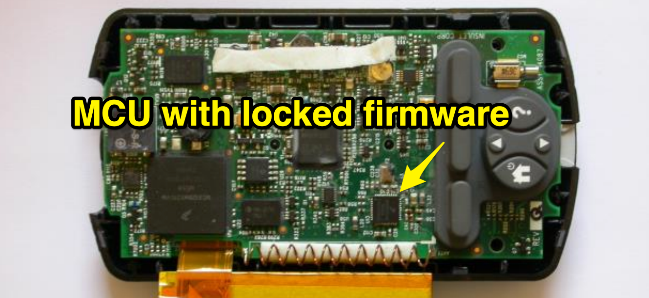
Several months passed almost to no avail. Finally, in the winter of 2016, a member of the group under the nickname @lorelaireported that she successfully copied the firmware from a larger ARM chip to PDM and began the tedious disassembly process: accepting the CPU instructions and turning them into human-readable code with semantic variables and function names. She did an amazing job finding out the various methods that were used to transmit data.
I looked at one of the untitled routines and noticed that it looked like a standard implementation of CRC calculation from a table. And the table had values for the standard 16-bit CRC. I wrote my own implementation on tables, and it was tested like a regular CRC. Then I carefully looked at how the function was written. A normal CRC implementation looks like this:
while (len--) {
  crc = (crc << 8) ^ crctable[((crc >> 8) ^ *c++)];
}
Their implementation looked like this ::
while (len--) {
  crc = (crc >> 8) ^ crctable[((crc >> 8) ^ *c++)];
}
Notice the difference? What was supposed to be a bitwise left shift operator was somehow encoded as a right shift. This is mistake; There is no reason to cripple your own CRC algorithm, as this makes it difficult to identify corrupted messages.
We are back in operation! And they resumed work on decoding messages, recording sessions from PDM for the delivery of boluses [drugs], temporary bases [Temporary Basal Rate determines an increase or decrease in insulin delivery - approx. lane], suspension of filing, etc.
Single use number
All insulin delivery teams had a 4-byte piece of data at the beginning of the message, which looked like some form of cryptography. Again, we tried many different ways of interpreting and analyzing it in the context of the messages in which it was sent, but it was not CRC (sometimes we saw the same 4 bytes even in different messages). And sometimes we saw the picture repeat itself. It looked, perhaps, as part of a protocol to prevent data reproduction. In other protocols, a similar function is called nonce .
One of the options that we considered was recording a message base for playing back given commands. Even if the address of each module was different, now we knew how to generate a CRC, so that we could take the previous copy of the command, put the new address on the message and recount the CRC. Only this nonce prevented us from using this strategy. Regardless of the command, the module only accepted the next nonce in the sequence, and we did not know how to generate the next nonce.
But! After all, we have a decompiled PDM firmware, we can just look there! So, we studied the PDM firmware, tracked the generation of messages in the code and found where these four bytes should be. But instead of a method that computes some cryptographic nonce, we just found four characters
INS.. What nonsense?!?! Well, somehow this message area needs to be updated later in the pipeline. There was another chip on the PDM, closer to the radio. It was the same chip that was used in the modules, with the identifier SC9S08ER48, which was not documented on the Internet. It was probably made to order for the Insulet. Maybe we can remove the firmware from this chip. Unfortunately, the chip was blocked, which prevented the copying of the firmware.
Work slowed down again ... it was like a real dead end. We put all our mental efforts into this nonce, and we did not have any good leads in the math behind it. And the ER48 chip, which (possibly) kept secrets, was blocked, and it’s hard to find any public information that would help to crack it.
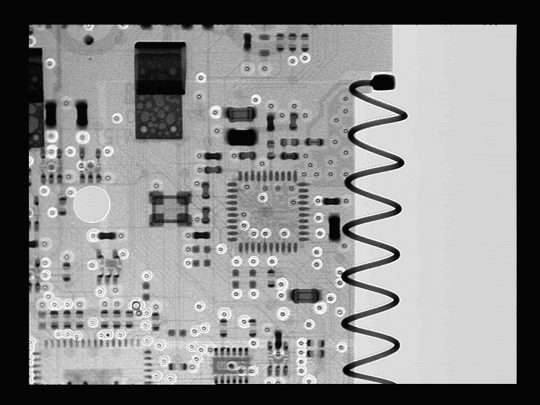
X-rays
Trying to understand ER48, some members of the Slack community suggested taking x-rays. It was really cool, but, unfortunately, did not open any new opportunities.
General shot
Detailed shot
Autopsy and shooting
Dan Caron decided to turn to a researcher, Dr. Sergey Skorobogatov from the University of Cambridge in the UK. Dan read that he has experience extracting code from locked chips, and convinced him to take a look at our problem. Dr. Skorobogatov conducted research in the field of using SEM (scanning electron microscope) for reverse engineering of microcircuits. He suggested that it is possible, but it will be expensive, require expensive equipment and does not guarantee a result. Joe Moran, who recently started using Loop after we met at the Nightscout hackathon in the fall of 2016, agreed to help with the project. He agreed with a Silicon Valley company, Nanolab Technologies, to open and photograph the chips, and also kindly funded the work of Nanolab and Dr. Skorobogatov (as well as his personal modules).
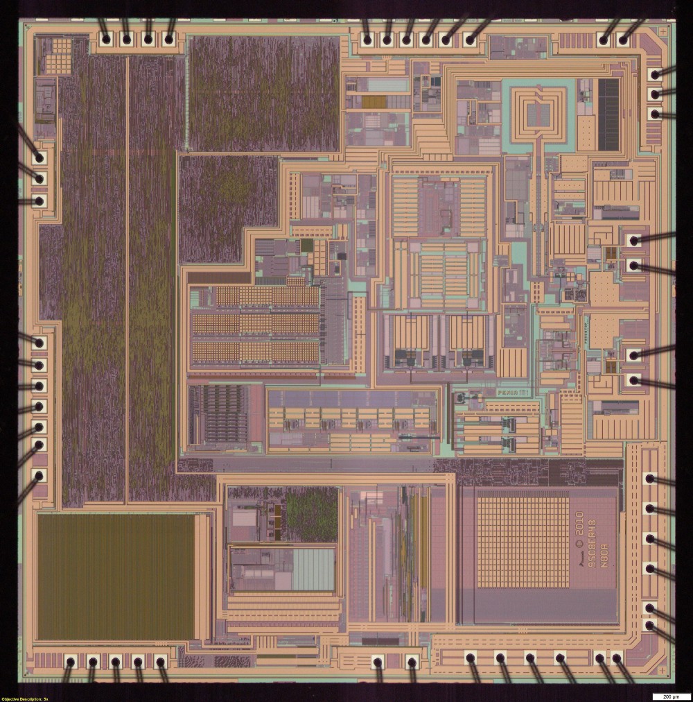
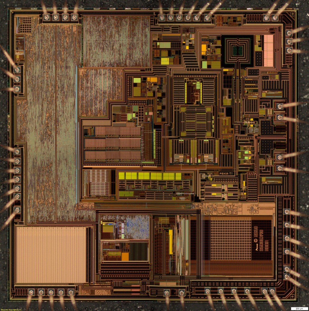
Dr. Skorobogatov asked Nanolab to apply various imaging techniques to find out if it is possible to crack the protection with known non-invasive or semi-invasive methods. As a result, many images appeared, some of them very beautiful. These are optical microscopic images of a silicon matrix.
General view of the microcircuit under an optical microscope
General view of the microcircuit under an optical microscope
Pictures were also taken of specific areas of the matrix using a scanning electron microscope. With different voltages, different surface preparation and different equipment.
SEM image of flash cells. Shows no data
Unfortunately, none of these images showed the actual contents of the flash memory.
Dr. Skorobogatov had one last method, which can be used only in case of failure. This was a patented method, the use of which had to obtain the permission of the university. Dr. Skorobogatov did the initial test and confirmed that he was able to read data on this chip. But before continuing, it was necessary to sign the NDA, and therefore negotiations were held on who would receive the contents of the extracted firmware.
Ultimately, the NDA signed the Nightscout foundation, and took responsibility for preventing the unauthorized disclosure of memory extraction methods and results.
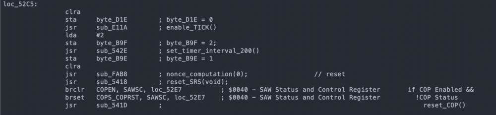
The result of this agreement and work was an incredible article.written by Dr. Sergei Skorobogatov, as well as the firmware code. From the first time there were quite a few errors in the code, but this was enough to get started. At the Nightscout Spring Hackathon, Joe turned to the guys if anyone would like to do disassembly. No one raised his hands. Turning processor instructions into something understandable is painstaking work, and very few people know how to do it. I tried to delve into assembler using the CPU documentation, but I achieved very little and was disappointed. Others optimistically asked for the firmware code with expectations of rapid progress, then realized the scale and complexity of the task - and quietly fell off.
SC908 instruction disassembly example
It turns out that Joe also had extensive experience working with assembler, and he began to carry out this difficult task. In July, Dr. Skorobogatov completed a second memory extraction operation with much fewer errors. During the summer, Joe Moran worked tirelessly to display a huge number of processor instructions and gradually integrate them into the overall picture of the module pseudocode.
In the end, Ken Shirriff , an expert in hardware reverse engineering, joined us , and he greatly accelerated the process. Together, Joe and Ken ended up translating enough code to find a function that encodes nonce. This happened in September 2017.
RileyLink and Loop
We have updated the Python scripts openomni , but now it's time to focus on RileyLink + iOS, so I started working on OmniKit and firmware updates for RileyLink. I believed that we had the basics of the protocol, and the rest was just details. Again, completely underestimating how much is yet to come.
I had to write a new firmware that handles modulation and coding of the module. I also had to rewrite how two chips on RL talk to each other in order to process zeros, since in Medtronic zeros were the special end of the packet marker. Much of Loop had to be redesigned to support multiple pumps, as well as new interfaces to support pairing, deactivation, and error handling. Fortunately, Nate Wrecliftlaid a solid foundation at Loop to make it all possible.
Meanwhile, work continued on understanding the format of the teams. Everything was carefully documented on the openomni wiki , the most comprehensive documentation of the protocol. Joe, Evarist and Elke Jäger have done a really great job over time in decoding messages and updating pages. Various Slack channel members have contributed to the capture of PDM packets and the module to help the overall decoding efforts.
Decoding was a fun job, with a lot of small victories, as each component of each team decrypts, and I really liked working on this part, gradually adding code to Loop. In April 2018, I shared at Slack that I did "primary cannulation paired via iPhone + RL according to the programmed basal schedule, and then 5 units became ill."
RL 2.0 firmware was completed in July 2018, and new deliveries have already gone with it. It was hoped that these boards could be used with Loop and Omnipod, but the existing 915 MHz antenna was too bad to work effectively at 433 MHz.
Decoding and implementation have progressed significantly over the summer, and Loop is gradually approaching performance. Joe did the amazing thing by giving me funding so I quit my day job and focus on this project, and eventually I joined the wonderful Tidepool team. Of course, in the field of DIY and the legislative regulation of medical equipment there were more events that I will not cover, but it was a very interesting summer!
Screamers
When more functions appeared in the driver, I connected it to Loop, turning on the ability to automatically configure delivery on time. At this stage, “flashy” modules were often obtained when some of the internal module checks found a problem and he stopped delivering insulin.
But this seemed to be a solvable problem, as we continued to find small discrepancies in the Loop packages and the original PDM when sending commands manually, and I assumed that if we fix them all, the “screams” will stop.
Work Loop!
On October 3, 2018, Joe donned the Loop managed module and became the first Loop Omnipod user, although he did not tell me right away because he knew that I would be worried. When he told me, I was still worried. We saw how the module worked and understood the functionality, and the basic algorithm was tested for a long time, but still ...
A month later, at the Nightscout hackathon in November 2018, several more adventurers decided to try it for themselves, and also became part of a small a closed testing group that will grow to more than 30 people before the code is published.
Unfortunately, we still encountered module “screams”, often occurring before the completion of the full three days of use, and we carefully compared Loop commands with PDM samples. In this process, Elke was especially useful: he wrote a script for automatically checking commands with original versions. I began to worry that the intermittent operation of the modules was caused by increased battery requirements for communications every five minutes.
The taps of the power supply voltage regulator in the module, drilled through the plastic of the rear panel, are super-glued.
Therefore, I began to measure the power supply voltage of the module using Arduino, write data and save them in a local database for visualization. I compared PDM and Loop.
Long-term change in module supply voltage
Unfortunately, this also turned out to be a dead end; using PDM and injecting a large amount of insulin, I could bring the module to a lower voltage than during the entire life of the Loop module, and could not make the module “scream”. It seemed that stress was not a problem, there must be something else.
RileyLinks with 955 MHz (left) and 433 MHz coil antennas (right)
At some point I noticed that if the exchange of messages with the module failed, the module sometimes continued trying to end the exchange by resending packets again and again. The testers logs also showed a lot of glitches, so I started experimenting with antennas. Both problems should be related to the quality of communication. I planned to try different antennas and ordered them in different places on the Internet, but I did not have time to test them until this became a priority.
I had several 433 MHz flexible antennas that can be attached to the inside of the RL enclosure. They often show better performance in some scenarios, but not in others; too unreliable. When I got to the reel, it showed good performance very consistently and on very amazing ranges. Time to make a new case for RileyLink.
With a new antenna and some optimizations that reduced messaging while still making adjustments every 5 minutes, screams became very rare. Probably comparable to the usual use of modules with PDM. Over the past 7,500 hours of real-time testing, 94% of the modules completed without fail.
Testing and documentation
The testing group slowly grew: new users constantly joined the system, who with a fresh look could evaluate which parts look confusing. These testers put up with a lot of flashy modules and made a very big contribution to improving Loop's performance with Omnipod. Basically, they sent problem reports and work logs.
These reports have a log of messages that can be analyzed using a tool made by Elke. It gives an idea if we get any distorted commands, and also allows you to collect statistics on certain parts of the interaction of Loop with modules.
Marion BarkerJoined the testing group and added special reporting and additional statistics on testing progress - and we were able to use its statistics of successful modules against failures to have an idea of progress at a high level.
In the end, Katie DiSimone joined the testing group . She began a major restructuring of loopdocs.org with documentation on using Loop with multiple devices. The wait for the version of Loop that worked with Omnipod was incredibly high, and without good documentation it was clear that we would be overwhelmed with the same questions.
New Loop Features
Integration with Omnipod required a rethinking of some of the interface elements and the addition of new controls. The module does not report the battery, and the user can do little with a low charge if this happens, so displaying the battery level widget does not make sense. In addition, without a user interface on the pump, the user should be able to quickly cancel the bolus. The tank icon depicted the Medtronic tank, so we wanted to remake it. Thanks to Paul Forgione for developing the logo of the module, which now shows the level of the tank.
Acknowledgments
Thanks to all the people who helped us go this long way so that we realize the goal that we set a long time ago. I know that I did not mention all involved and not all events. This is not possible in one article, and I have only personal experience. It is hard to imagine how many hours it took. If you add them all together, I’m sure it’s a shocking figure. Not to mention the work on creating the Omnipod itself, which, it seems to me, overshadows all these efforts. So thank you all. In addition, many of these hours would otherwise have been spent with families. I really appreciate the understanding of my wife and children because of the time I spent on it, and I want to thank them too.
Notes
I should mention Joachim Ornstedt as one of the contributors to openomni decoding, as well as the creator of probably the first integration with omnipod. He built a device that used optical character recognition (OCR) to extract data from the PDM, and connected the number buttons to the physical PDM through another microcontroller. This approach is difficult to scale, but it is very smart and bypasses many of the problems that we had to deal with a solution based on RE. I really admire how he dealt with the problem and set up work for a tiny fraction of the time it took to get the device to work with Loop.