How machines communicate: Modbus protocol

The Modbus protocol is the most common industry protocol for M2M communication. It is a de facto standard and is supported by almost all manufacturers of industrial equipment.
Due to its versatility and openness, the standard allows the integration of equipment from different manufacturers. Modbus is used for collecting readings from sensors, controlling relays and controllers, monitoring, etc.
In the article we will analyze the implementation of the Modbus protocol, data formats, software for working with the protocol. Let's try to read data from the device in practice.
History of Modbus
Modbus was introduced in 1979 by Modicon (now Schneider Electric). It was an open standard operating on the RS-232 interface. Later, protocol implementations for RS-485 and Modbus TCP interfaces appeared. The protocol quickly gained popularity, and many manufacturers began to implement it in their devices.
Later, the rights to the protocol were transferred to the non-profit organization Modbus Organization , which until today owns the standard.
The Modbus standard uses terminology derived from ladder logic . So, for example, some registers are called coils (English coil).
Physical level
- RS-232/422/485 are serial interfaces widely used in industry. RS-422/485 interfaces provide signal range up to 1200 meters. Modbus RTU / ASCII protocols used
- TCP / IP networks - any ethernet interfaces can be a physical data transmission channel. Using Modbus TCP protocol
Logic level

Modbus Protocol Differences
Modbus ASCII
The data is encoded with characters from the ASCII table and transmitted in hexadecimal format. The beginning of each packet is indicated by a colon, and the end by carriage return and line feed. This allows the protocol to be used on lines with longer delays and equipment with less accurate timers.
Modbus RTU
In the Modbus RTU protocol, data is encoded in binary format, and a time interval serves as a packet separator. This protocol is critical to delays and cannot work, for example, on modem lines. At the same time, the overhead for data transfer is less than in Modbus ASCII, since the message length is less.
Modbus TCP
The packet structure is similar to Modbus RTU, the data is also encoded in binary format, and packaged in a regular TCP packet for transmission over IP networks. The integrity check used in Modbus RTU is not applied, since TCP already has its own integrity control mechanism.
Package format

Package Formats of Different Modbus Implementations
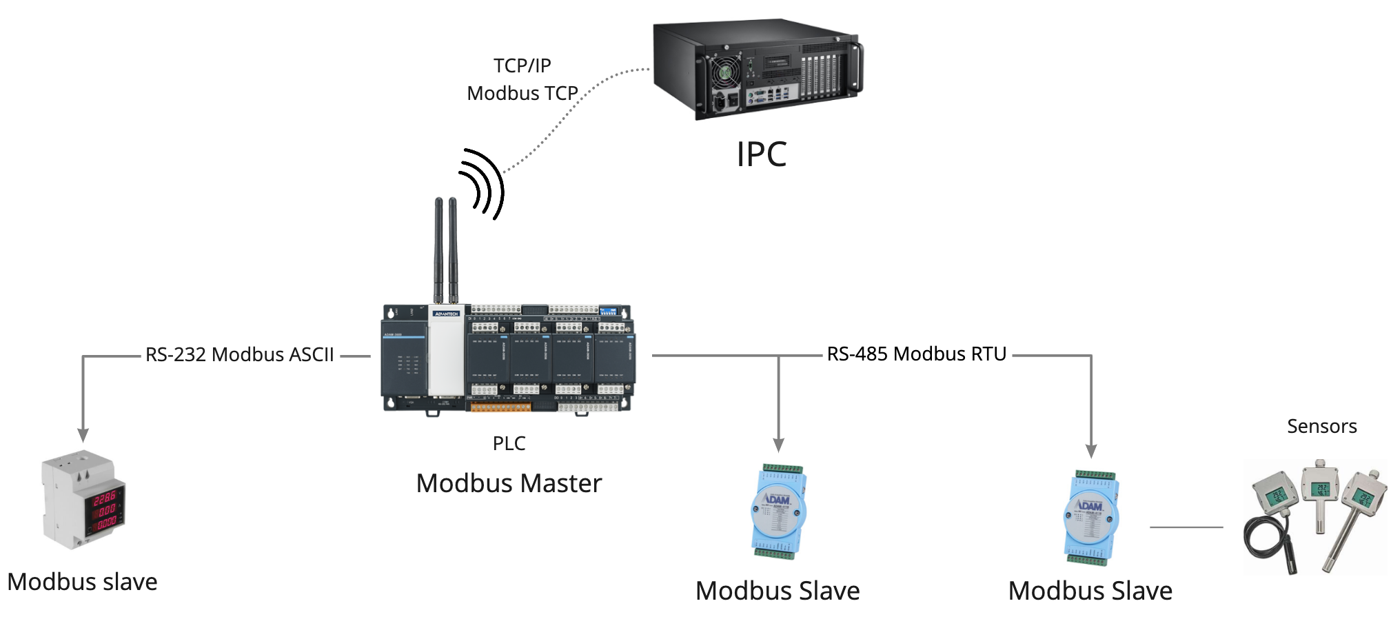
All Modbus devices interact according to the master-slave model. Requests can be initiated only by the master device, slaves can only respond to requests, and cannot start data transfer on their own. Depending on the protocol implementation, the packet headers are different. Here are the main components of the package that are important to know:
ADU (Application Data Unit) - the entire Modbus package, with all the headers, PDUs, checksum, address and tokens. It differs depending on the implementation of the protocol.
PDU (protocol data unit) - the main part of the package, the same for all implementations of the protocol. Contains payload itself.
Device address- the address of the recipient, that is, the slave device. Up to 247 devices can be located in one segment of a Modbus network. Only slaves have different addresses, the master has no address. Address “0” is used for broadcast requests from the master, while slaves cannot respond to these broadcast packets.
Checksum - packet integrity algorithms. Modbus RTU and ASCII use 2 bytes of checksum. Modbus RTU uses the CRC16 algorithm, while Modbus ASCII uses the simpler and less reliable LRC8. In Modbus TCP, the checksum is not added to the ADU since integrity is checked at the TCP level.
We will not analyze additional headers specific to each individual protocol implementation, since this is not significant when working with the protocol at the application level.
Modbus Registers and Functions
In a simplified form, the Modbus request structure consists of a function code (read / write), and data that needs to be read or written. At the same time, function codes differ for different data types. We will analyze what registers are and the functions for working with them.
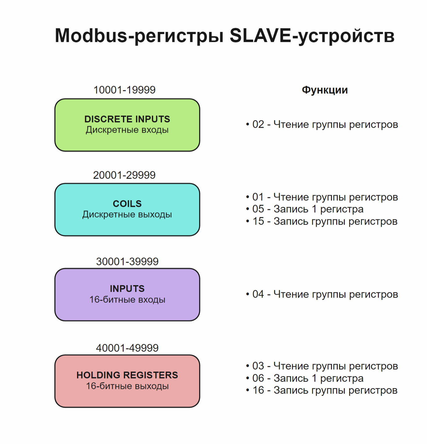
- Discrete Inputs - Discrete inputs of the device are read-only. Range of register addresses: from 10001 to 19999. They have a function “02” - reading a group of registers
- Coils - discrete outputs of the device, or internal values. Available for reading and writing. The range of register addresses is from 20001 to 29999. It has functions: “01” - reads a group of registers, “05” - writes a single register, “15” - writes a group of registers
- Input Registers - 16-bit device inputs. Read only. Range of register addresses: from 30001 to 39999. Have a function: "04" - read a group of registers
- Holding Registers - 16-bit device outputs, or internal values. Available for reading and writing. The range of register addresses: from 40001 to 49999. Have
Despite the names, the inputs and outputs can actually be internal variables, store counters, flags, or be control triggers. There are also other ranges of registers, but in the vast majority of devices they are not used, so we will consider four main types of registers. Different devices can use different ranges of registers, or all at once.
Work examples
For an example of working with the Modbus TCP protocol, we will use the simplest console utility modbus-cli , written in Ruby. It makes it easy to read and write data to Modbus registers.
Let's try to read the status of the counters of transmitted packets on an industrial switch Advantech EKI-5524SSI. First you need to determine the addresses of the registers that store the necessary information, for this, look at the documentation of the device. Register descriptions are located in the Modbus Mapping Table section:
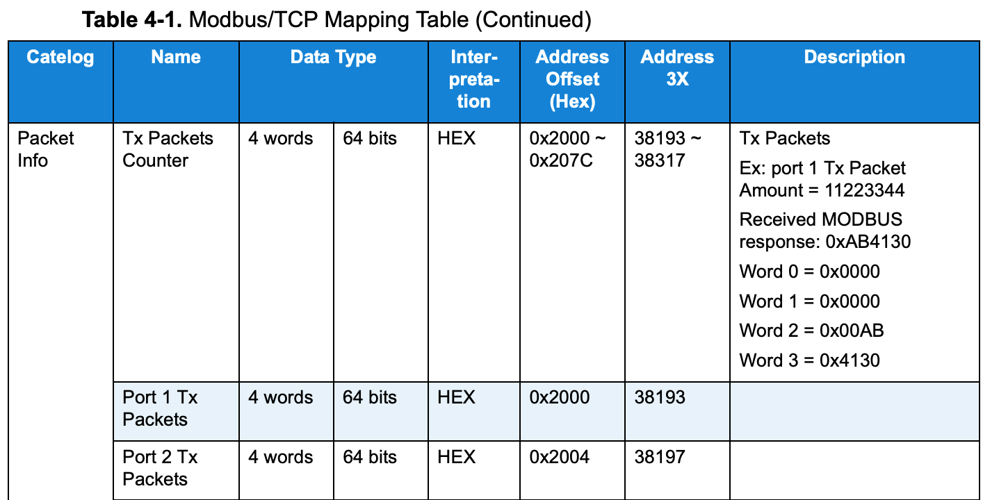
Register values are described in the EKI switch documentation.
It can be seen that the value of the transmitted packets for one port is stored in four registers, and for the first port these are registers 38193 through 38197. A description is also given of the data storage format, from which it follows that the integer number of transmitted packets is stored in hexadecimal format, and the value of 11223344 packets will be written as 0xAB4130, from right to left.
Make a request:
$ modbus read 192.168.0.17 38193 4
38193   0x0000
38194   0x0000
38195   0x0000
38196   0x3459
read is a read command. The program itself understands which specific read command to use depending on the address of the register, in our case the “04” command will be used to read 16-bit registers.
192.168.0.17 - IP address of the device.
38193 - The starting address of the register.
4 - offset relative to the start address. We read four registers for port 1, as follows from the datasheet.
We get an answer containing the values of four registers. We see that the number of packets is small: 0x3459, that is, 13401, - the switch was turned on recently.
Disadvantages of Modbus Protocol
In fairness, it is worth mentioning the shortcomings of the protocol. Since it was developed more than 40 years ago, when processor performance was significantly lower and protocols were developed without taking into account data protection, it has a number of minuses:
- The protocol does not provide authentication and encryption of transmitted data. Therefore, when using Modbus TCP, additional VPN tunnels must be used.
- The slave cannot initiate data transfer, so the master must constantly poll slaves
- Slave device cannot detect loss of connection with Master. This problem directly follows from the previous one.
However, despite all the shortcomings, Modbus is still the most common industrial protocol, and thanks to its openness, it makes it easy to combine devices from different manufacturers. Low resource requirements allow integrating the protocol into the most low-power devices.
Modbus enabled hardware
Advantech offers a wide range of industrial equipment with Modbus protocol support for any task: automation, control, data collection and transmission.
ADAM-6000 and WISE-4000 - Remote I / O Modules
 The modules of the ADAM-6000 and WISE-4000 series allow you to remotely control digital and analog inputs / outputs using the Modbus TCP protocol. Used to control peripheral devices and collect data in slave mode. They can be paired with a programmable logic controller, or connect directly to a SCADA server. ⠀⠀⠀ ⠀⠀⠀⠀⠀ ⠀⠀⠀⠀⠀ ⠀⠀⠀⠀⠀ ⠀⠀⠀⠀⠀ ⠀⠀⠀⠀⠀⠀⠀⠀⠀⠀ ⠀⠀⠀⠀⠀⠀⠀⠀⠀⠀⠀⠀⠀⠀⠀⠀⠀⠀⠀⠀ ⠀⠀⠀⠀⠀⠀⠀⠀⠀⠀⠀⠀⠀⠀⠀⠀
EKI-1200 - Modbus gateways for interface conversion

To convert Modbus RTU / ASCII protocols to Modbus TCP, Modbus gateways are used. The devices of the EKI-1200 series have on board up to four serial RS-232/422/485 interfaces, and two Ethernet ports. They allow you to combine devices with different protocols into one network. For example, connect a slave device that only supports Modbus RTU via RS-485 interface to a Modbus TCP network segment.
APAX-5000, ADAM-3600, WISE-5000 - automation controllers
The controllers support Modbus RTU functions as a slave / master and Modbus TCP client / server.

Application examples
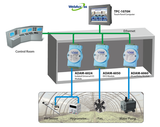
Greenhouse Monitoring System
The Advantech monitoring solution integrates the TPC-1070H, ADAM-6024, ADAM-6050, ADAM-6060, and WebAccess software in a machine cabinet next to farmland. By connecting to various sensitive devices, the ADAM-6000 modules can receive real-time environmental data and monitor equipment switching to ensure that the greenhouse is in the optimal environment for plant growth. Thanks to Advantech’s special function - graphical condition logic (GCL), users can define their own control logic rules and load these rules into the ADAM-6000 Ethernet I / O modules, and then the modules automatically execute logical rules like stand-alone modules. controller.
All received data is then transmitted via Ethernet to a computer with a TPC-1070H touch panel. Featuring a fanless cooling system and front panel compliant with IP65, the TPC-1070H is a rugged and compact design suitable for a changing operating environment, and its powerful computing capabilities can handle large amounts of data. For device management, Advantech WebAccess allows engineers or managers to view, monitor and configure the monitoring system via an intranet or the Internet using a standard web browser from any device, including tablets and smartphones.
Monitoring the solar water heating system
The engineering company should have been able to control the amount of solar energy, temperature, and water flow in a solar-powered water heating system for an Olympic-sized pool provided by their newly developed solar panel. They should also be able to directly monitor these values and their alarms on the LCD panels and store these values for future reference.
Advantech Adam Modules provided the customer with a solution that utilized data acquisition modules connected via RS485 and a two-wire bus to transmit data from all sensors. This system architecture has two main advantages: firstly, it allows you to add more sensors to the data collection modules at any time, and secondly, it is very easy to add additional tags to the software for monitoring and recording these values on a PC.
