Tesla Transformer on One Square Inch Board
- Transfer

Having seen the title of the article “One inch tesla coil”, at first I thought that it was a Tesla transformer one inch high. It turned out that it is slightly larger, but it is made on a board with an area of one square inch - these are the conditions of the competition . But even this is interesting enough to take up the translation.
According to the scheme, parameters and degree of danger, the design does not differ from that made from the average Chinese designer for the assembly of the Tesla transformer. They work well, but the place on the board, according to the author, was used irrationally - how can one not try to reduce it?

The composition of the device:
1 pc. printed circuit board
2 pcs. 2 kΩ resistor
2 pcs. 10 kΩ resistor
2 pcs. 3 mm LED
1 pc. 1 uF electrolytic capacitor
1 pc. lavsan capacitor of the same capacity
1 pc. transistor IRF530
1 pc. transistor TIP41
1 pc. two turns of hard wire (counterclockwise)
1 PC. a winding of 350 turns of a winding wire on a PVC pipe with an external diameter of 20 mm The
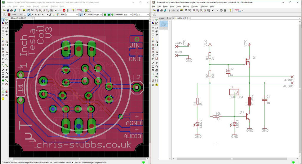
audio input from such designers is often included in the standard package, and here it is copied along with the rest of the circuit:
The boards came to the author shortly before the trip to the EMFcamp festival, and he decided to take them there with the details and assemble them there. But everyone who has been to such festivals knows that this cannot be done. You always do not have time to do everything that is planned, or at least as planned.
For some reason, the author considered that it was better to take up work at the “peak of Ballmer,” and of course, nothing worked. Returning home, he double-checked everything - it turned out that everything was assembled correctly, which means that something was wrongly designed. Comparing his circuit with several similar ones, he realized that one of the LEDs is involved in the bias circuit of the bipolar transistor. A small adjustment - and everything works. The scheme attached to the article is correct.
Links: circuit and board, both in EAGLE format.
Assembly should begin by soldering all components except transistors and windings. Then install the transistors on the heat sinks (with thermal grease), and then solder them. The heat sinks are also supports for the board. Glue the frame of the 350-turn winding to the board with hot-melt adhesive, solder one of its turns into the board. To wind a two-turn winding with a diameter of 30 mm counterclockwise and solder, the area closest to the number 1 in the article heading printed on the board corresponds to the beginning of the winding (if you did silk-screen printing, otherwise see the figure to the left of the diagram).
The design is ready, the supply voltage is from 15 to 24 V, the polarity is indicated on the board (again, in the presence of silk screen printing). Reviews of Chinese kits say that at 19 V the current consumption is about 1 A, and the area of heat sinks is not enough. If it is the same here, then the advice is the same: either do not turn it on for a long time, or cool with a fan.
If you use the audio input, make a cable long enough so that the signal source can be far from the device. The common wire of the signal source cannot be connected to the common wire of the power source of the device. The signal is better fed through a capacitor, even better - through an isolation transformer.
Now at Hackaday.io another author is working on an even more interesting Tesla transformer - with printed coils. You do not need to wind anything - just make a board and solder three components into it. But there is no scheme laid out yet - only the device is shown in action.