Nonstandard circuitry: seven-segment indicator on ATtiny13
We are not looking for simple ways.
Previous, it’s my first publication that caused a resonance among users of Habr. Decided not to stop. We continue to squeeze the impossible out of ATtiny13. I warn you right away, the solutions described are non-standard again, and someone may cause indignation and cognitive dissonance ("And what is the point of the article then? Show what elements can be connected?"). Moreover, such a solution is also really impractical, which I will write in more detail below. But it so happened that standard solutions have long been known, and reading about them is not always interesting, but writing is ungrateful.
I really like this kid ATtiny13. He has enough brains to solve many domestic problems (turn on the lights, ventilation,
In the process of studying the programming of microcontrollers (in the Arduino environment, just don’t tell anyone), I, like many, went through the step of connecting an ultrasonic distance sensor, something like this:
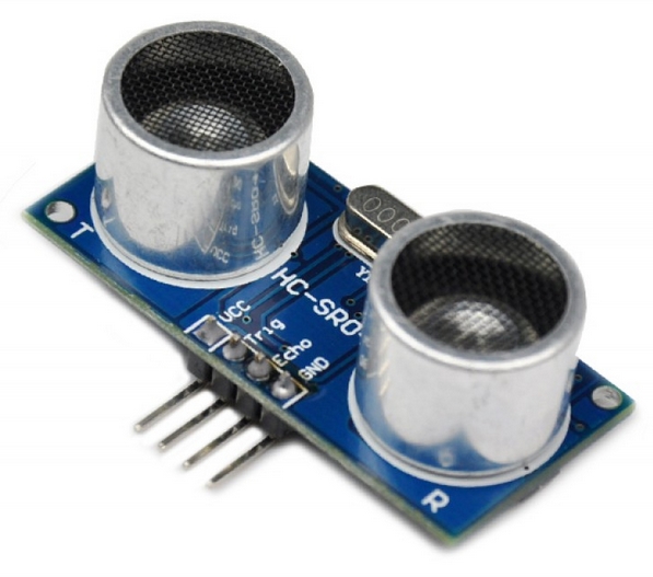
Since the method of transmitting information from the sensor to the controller is simple to disgrace, ATtiny13 copes with this easily. Then it was necessary to display information on a seven-segment indicator using shift registers. That is, the scheme of the display part was several times larger than the controller itself. At that moment I played around and moved on.
Recently, I thought, what else would be an overwhelming task to assign to Tinka? What she still could not handle in the described examples. The first thing I remembered about the indication. Some time ago I was already looking for information on a similar topic. Then I found such an interesting option.
Picture
21 segments from 5 feet of the controller. Wow! I don’t even need so much, two signs are enough, plus a dot, a total of 15 segments. And if with four legs? Then get a maximum of 13 segments, not enough. At the sight of the circuit, a desire arose immediately to assemble and try, although it is not easy to draw up an operation algorithm. But with a closer look, you understand that it will not work to collect, such seven-segmented animals do not exist in nature (most likely). You can make, of course, but this is a different level. Then the idea was postponed until better times.
Offtopic: Why are there no seven-segment indicators with integrated logic? Where are the developers looking? How convenient is the installation and control - two power legs and 3 (1, 2) data legs. And after all, they were even in the USSR: 490IP1, 490IP2. Inside the most ordinary indicator for 2 ... 4 digits there is plenty of space for placing the chip microcircuit, and the price of the shift register is 0.064 cu together with the case. Anyway.
And so I thought again, how to reduce the number of legs for working with the seven-segment indicator? The controller outputs can take three states (actually 4, but now it doesn’t matter). Is there any way to use this? If two states with respect to the LED can be interpreted only as shining, not shining, then with three it is a little more interesting. I have not yet figured out how to use it, but the following scheme came to my mind:

If the controller output is in the zero state, the LEDs do not light up (which is obvious).
If the output is in the unit state, then the LEDs are lit, which is also understandable.
But if the output is not the output at all, but is switched on to the input, then a current flows through the circuit of two resistors and LED HL1, creating a voltage drop at the connection point of the resistors of approximately (5-1.7) / (2.2 + 1.5) * 1.5 + 1.7 = 3.0 V. This is not enough for the current to flow through the VD1_R3_HL2 circuit (approximately 3.4 V is needed). VD1 is an additional LED used as a zener diode (the stabilizer is more correct), therefore we will not consider it an LED, so as not to get confused. It does not matter if the pull-up resistor is turned on inside the microcontroller, its resistance (20 kOhm) practically does not affect the situation. I didn’t come to such ratings right away, before that I tried with a regular diode as VD1, it also works pretty well with the same resistors R1 and R2. But it is better that R2 is about one and a half times larger than R1. And I almost forgot the most important thing:red LEDs both in the indicator and additional. In extreme cases, either the indicator or additional LEDs can be applied green. And with a supply voltage of 4.5 V to 5 V.
What do we have in the end? Three states: no LED (0) shines, HL1 (1) shines, or HL1 and HL2 (2) shine. Very similar to the ternary system. But we cannot light HL2 without HL1, this must be remembered. But now with the help of the four legs of the microcontroller we can control eight LEDs (I wanted to think so).
Then I tried to break up the indicator segments into pairs (just like in a kindergarten: a boy-girl). The main condition is that in each pair one of the segments cannot shine on its own, such discrimination. That's what I did:
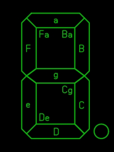
Four pairs of segments, in each capital letter the dominant segment is indicated, which can work by itself, the second can only with it. You may notice that segment “a” stirs up with two at once, and nobody got to the poor point at all. How it looks like life!
But with these pairs you can display (almost) all the numbers:
Picture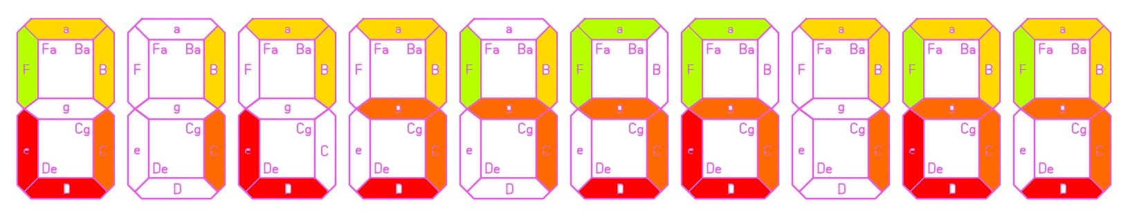
Each pair is painted in its own color. An attentive viewer noticed that something was wrong with the deuce. We will not focus on this for now. I tried a few more options for grouping segments, better not come up. Maybe someone will suggest. Perhaps the neural network could handle it.
At the second stage of the experiments, I had to use an indicator with a common anode. Therefore, the final scheme is as follows:
Scheme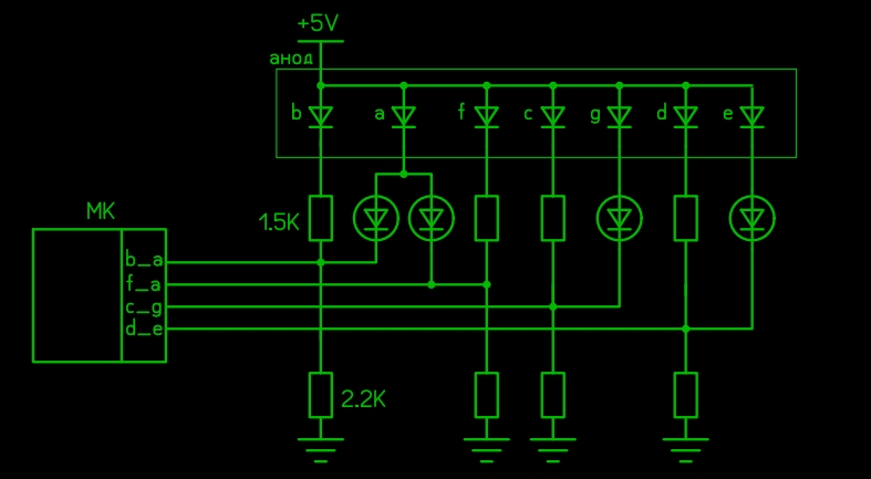
Someone may ask: where did the 100 ohm resistors go? It has long been known (and actively used) that with correctly made dynamic indications, current-limiting resistors can be dispensed with. Even if the voltage is constantly applied from the controller’s output to the two LEDs connected in series by mistake, the microcontroller and the LEDs normally withstand this, the current is limited by the transition resistance inside the MC. And more about resistors. The maximum current through HL1 according to the previous scheme is about 2 mA, and through HL2 it reaches 25 ... 40 mA (presumably, later I will tell you where these numbers came from). This means that the light output of different segments will be different. But since dynamic indication will be used, this can easily be solved due to the different display time of the segments.
All experiments I conducted on the Arduino Nano in the Arduino IDE. An excellent prototyping board, it gets good in the breadboard, it is flashed via USB without problems. Did something fail? I fixed the sketch and in a minute I uploaded a new firmware. And when you debugged the code, you can go to the firmware in ATtiny13, it still takes a little more gestures.
By the way, I am also flashing using Arduino in the Arduino environment, this practically eliminates the possibility of locking MK with the wrong fuses, and much easier.
Here is an example of displaying the number 4 in the code:
pinMode(f_a, INPUT); // ножку подключения сегментов f_a делаем входом
digitalWrite(f_a, 1); // зажёгся сегмент F
pinMode(d_e, OUTPUT); // ножку подключения сегментов d_e делаем выходом
digitalWrite(d_e, 1); // ставим её в состояние 1, при этом не светят D и E
pinMode(b_a, INPUT); // ножку подключения сегментов b_a делаем входом
digitalWrite(b_a, 1); // зажёгся сегмент B
pinMode(c_g, OUTPUT); // ножку подключения сегментов c_g делаем выходом
digitalWrite(c_g, 0); // ставим её в состояние 0, зажглись и C, и G
delayMicroseconds (150); // F, B, C, G cветят ещё 150 микросекунд
pinMode(c_g, INPUT); // ножку подключения сегментов c_g делаем входом
digitalWrite(c_g, 1); // теперь сегмент G потух, светится только сегмент С
delay (time_2); // F, B, C cветят ещё 2 миллисекунды
In principle, everything should be clear even to those who are not familiar with Arduino, but understand a little about the controllers. Figures of 150 microseconds and 2 milliseconds are selected experimentally by the brightness of the segments. In the final code, you need to put them in separate variables so that you can change them during debugging. From these figures it is possible to approximately determine the order of difference in currents across two segments in one pair. Since the G segment glows about 13 times less than the others and provides the same brightness, it can be assumed that the current through this segment is 13 times more than through the others. In fact, the dependence of the brightness on the current is nonlinear, so the current can be 25 times larger, i.e. 50 mA. That with such a duty cycle is quite safe for the output of MK. By the way, this difference in currents played into the hands when solving the problem of figure 2. As I wrote above, segment G can be illuminated only along with segment C. But if you apply 0 to the MK leg, which is responsible for C and G, for 150 microseconds, and after 2 ms keep it on 1, then segment G will work out at full brightness, and segment C for the same 150 microseconds, it will only have time to highlight a little. We get an almost full two. Thus, I managed to break the rule that I myself established. What can not be done from hopelessness.
So, we lit the figure with the four legs of the MK. Actually, I missed this stage for myself, immediately displayed two characters. To do this, disconnect the output of the common anode of one of the indicator bits from the power plus, and connect to another MK pin, and the anode of the other discharge to the next output (6 legs already). Now, in turn, set 1 on the anode of the least significant digit, display the digit of the least significant digit, then 1 on the anode of the least significant digit, and display the digit of the highest digit, and so on in a circle. I conducted this experiment with Arduino Nano, she has enough legs. All code was debugged on it, not the first time. And so it worked, as it should.
Scheme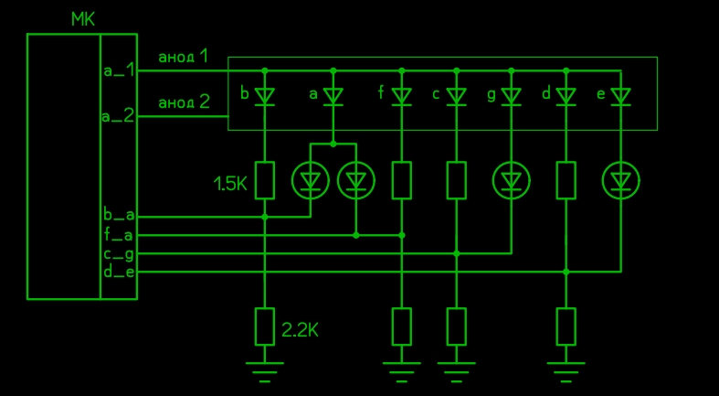
Since the anodes are connected in turn, with the help of a simple refinement, one more output of the MK can be released. Here is the summary diagram:
Scheme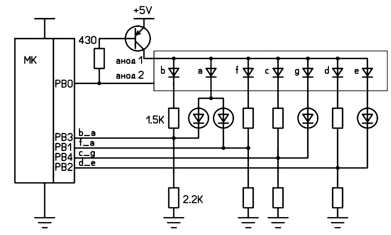
Total use 5 legs MK to display a two-digit number. At this stage, you can already try with the baby ATtiny. Which I did. But not at once. A sketch compiled in an Arduino environment for ATtiny13 took up approximately 1.7 kB of memory with 1 kB available. To reduce the size, I had to turn to the ports directly, which I was going to do later. By the way, on Arduino I used the same ports that I was going to use on ATtiny, it’s very convenient. They are already indicated in the last diagram. After processing, the code lost one kilobyte.
Here is the resulting code for ATtiny13:
The code
#define  time_2  2 // время отображения неярких сегментов, миллисекунд
#define  time_3  150 // время отображения ярких сегментов, микросекунд
byte in1_;
byte in2_;
int disp_;
int d_ = 0;
void setup()
{
}
void loop()
{
  d_ = d_ + 1;
  if (d_ > 150) { // просто раз в 150 циклов увеличиваем число на 1
    d_ = 0;
    disp_ = disp_ + 1;
    if (disp_ > 99)(disp_ = 0); // считаем от 0 до 99
  }
    in2_ = disp_ / 10; // пишем в левый разряд - цифру делёную на 10
    in1_ = disp_ % 10; // пишем в правый разряд цифру оставшуюся от деления на 10
  }
  switch (in1_) {
    case 0:
      DDRB = B00001111;
      PORTB = B00010000;
      delayMicroseconds (time_3);
      DDRB = B00000001;
      delay (time_2);
      break;
    case 1:
      DDRB = B00000111;
      PORTB = B00000110;
      delay (time_2);
      break;
    case 2:
      DDRB = B00011111;
      PORTB = B00000010;
      delayMicroseconds (time_3);
      DDRB = B00010011;
      PORTB = B00010010;
      delay (time_2);
      break;
    case 3:
      DDRB = B00011011;
      PORTB = B00000110;
      delayMicroseconds (time_3);
      DDRB = B00000011;
      delay (time_2);
      break;
    case 4:
      DDRB = B00010101;
      PORTB = B00001110;
      delayMicroseconds (time_3);
      DDRB = B00000101;
      delay (time_2);
      break;
    case 5:
      DDRB = B00011011;
      PORTB = B00001100;
      delayMicroseconds (time_3);
      DDRB = B00001001;
      delay (time_2);
      break;
    case 6:
      DDRB = B00011111;
      PORTB = B00001000;
      delayMicroseconds (time_3);
      DDRB = B00001001;
      delay (time_2);
      break;
    case 7:
      DDRB = B00001111;
      PORTB = B00010110;
      delayMicroseconds (time_3);
      DDRB = B00000111;
      delay (time_2);
      break;
    case 8:
      DDRB = B00011111;
      PORTB = B00000000;
      delayMicroseconds (time_3);
      DDRB = B00000001;
      delay (time_2);
      break;
    case 9:
      DDRB = B00011011;
      PORTB = B00000100;
      delayMicroseconds (time_3);
      DDRB = B00000001;
      delay (time_2);
      break;
  }
  switch (in2_) {
    case 0:
      DDRB = B00001111;
      PORTB = B00010001;
      delayMicroseconds (time_3);
      DDRB = B00000001;
      delay (time_2);
      break;
    case 1:
      DDRB = B00000111;
      PORTB = B00000111;
      delay (time_2);
      break;
    case 2:
      DDRB = B00011111;
      PORTB = B00000011;
      delayMicroseconds (time_3);
      DDRB = B00010011;
      PORTB = B00010011;
      delay (time_2);
      break;
    case 3:
      DDRB = B00011011;
      PORTB = B00000111;
      delayMicroseconds (time_3);
      DDRB = B00000011;
      delay (time_2);
      break;
    case 4:
      DDRB = B00010101;
      PORTB = B00001111;
      delayMicroseconds (time_3);
      DDRB = B00000101;
      delay (time_2);
      break;
    case 5:
      DDRB = B00011011;
      PORTB = B00001101;
      delayMicroseconds (time_3);
      DDRB = B00001001;
      delay (time_2);
      break;
    case 6:
      DDRB = B00011111;
      PORTB = B00001001;
      delayMicroseconds (time_3);
      DDRB = B00001001;
      delay (time_2);
      break;
    case 7:
      DDRB = B00001111;
      PORTB = B00010111;
      delayMicroseconds (time_3);
      DDRB = B00000111;
      delay (time_2);
      break;
    case 8:
      DDRB = B00011111;
      PORTB = B00000001;
      delayMicroseconds (time_3);
      DDRB = B00000001;
      delay (time_2);
      break;
    case 9:
      DDRB = B00011011;
      PORTB = B00000101;
      delayMicroseconds (time_3);
      DDRB = B00000001;
      delay (time_2);
      break;
  }
  DDRB = B00011111;//пауза между отображениями
  PORTB = B00011110;
  delay (5);
}
The above code will allow your ATtiny13 to read from 0 to 99. It would be more correct to provide for the possibility of reassigning the MK legs. Programming gurus could reduce the code several times ( Where is the minimum Hello World limit on AVR? ).
You can add the necessary function to the code so that MK displays something conscious. True, Tinki already has all her legs occupied. There is also a reset leg that can be used as an input / output port. But using it was harder than I thought. Therefore, for myself I leave "for later." But there is an interesting feature that not everyone knows about. The analog input ADC0 is output to the same leg, and it works! True, when the voltage on it is less than 1/4 of the supply voltage, the MK goes into reset mode. But from 1/4 to the supply voltage, it is quite possible to measure the input voltage. I took advantage of this:
The code
#define  time_2  2 // время отображения неярких сегментов, миллисекунд
#define  time_3  150 // время отображения ярких сегментов, микросекунд
byte in1_;
byte in2_;
int disp_;
int d_ = 0;
void setup()
{
}
void loop()
{
  d_ = d_ + 1;
  if (d_ > 50) { // раз в 50 циклов...
    d_ = 0;
    disp_ = analogRead(A0) / 10; // ...измеряем напряжение на входе, делим на 10, чтобы вложиться в диапазон.
    if (disp_ > 99)(disp_ = 99);
    in2_ = disp_ / 10; // пишем в левый разряд - цифру делёную на 10
    in1_ = disp_ % 10; // пишем в правый разряд цифру оставшуюся от деления на 10
  }
  switch (in1_) {
    case 0:
      DDRB = B00001111;
      PORTB = B00010000;
      delayMicroseconds (time_3);
      DDRB = B00000001;
      delay (time_2);
      break;
    case 1:
      DDRB = B00000111;
      PORTB = B00000110;
      delay (time_2);
      break;
    case 2:
      DDRB = B00011111;
      PORTB = B00000010;
      delayMicroseconds (time_3);
      DDRB = B00010011;
      PORTB = B00010010;
      delay (time_2);
      break;
    case 3:
      DDRB = B00011011;
      PORTB = B00000110;
      delayMicroseconds (time_3);
      DDRB = B00000011;
      delay (time_2);
      break;
    case 4:
      DDRB = B00010101;
      PORTB = B00001110;
      delayMicroseconds (time_3);
      DDRB = B00000101;
      delay (time_2);
      break;
    case 5:
      DDRB = B00011011;
      PORTB = B00001100;
      delayMicroseconds (time_3);
      DDRB = B00001001;
      delay (time_2);
      break;
    case 6:
      DDRB = B00011111;
      PORTB = B00001000;
      delayMicroseconds (time_3);
      DDRB = B00001001;
      delay (time_2);
      break;
    case 7:
      DDRB = B00001111;
      PORTB = B00010110;
      delayMicroseconds (time_3);
      DDRB = B00000111;
      delay (time_2);
      break;
    case 8:
      DDRB = B00011111;
      PORTB = B00000000;
      delayMicroseconds (time_3);
      DDRB = B00000001;
      delay (time_2);
      break;
    case 9:
      DDRB = B00011011;
      PORTB = B00000100;
      delayMicroseconds (time_3);
      DDRB = B00000001;
      delay (time_2);
      break;
  }
  switch (in2_) {
    case 0:
      DDRB = B00001111;
      PORTB = B00010001;
      delayMicroseconds (time_3);
      DDRB = B00000001;
      delay (time_2);
      break;
    case 1:
      DDRB = B00000111;
      PORTB = B00000111;
      delay (time_2);
      break;
    case 2:
      DDRB = B00011111;
      PORTB = B00000011;
      delayMicroseconds (time_3);
      DDRB = B00010011;
      PORTB = B00010011;
      delay (time_2);
      break;
    case 3:
      DDRB = B00011011;
      PORTB = B00000111;
      delayMicroseconds (time_3);
      DDRB = B00000011;
      delay (time_2);
      break;
    case 4:
      DDRB = B00010101;
      PORTB = B00001111;
      delayMicroseconds (time_3);
      DDRB = B00000101;
      delay (time_2);
      break;
    case 5:
      DDRB = B00011011;
      PORTB = B00001101;
      delayMicroseconds (time_3);
      DDRB = B00001001;
      delay (time_2);
      break;
    case 6:
      DDRB = B00011111;
      PORTB = B00001001;
      delayMicroseconds (time_3);
      DDRB = B00001001;
      delay (time_2);
      break;
    case 7:
      DDRB = B00001111;
      PORTB = B00010111;
      delayMicroseconds (time_3);
      DDRB = B00000111;
      delay (time_2);
      break;
    case 8:
      DDRB = B00011111;
      PORTB = B00000001;
      delayMicroseconds (time_3);
      DDRB = B00000001;
      delay (time_2);
      break;
    case 9:
      DDRB = B00011011;
      PORTB = B00000101;
      delayMicroseconds (time_3);
      DDRB = B00000001;
      delay (time_2);
      break;
  }
  DDRB = B00011111;//пауза между отображениями
  PORTB = B00011110;
  delay (5);
}
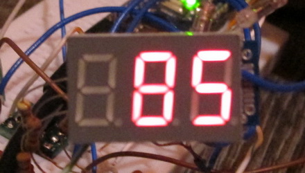
Experience shows that the indicator can be reduced to as much as 21, only then the MK goes into reset mode and starts to work when it returns to about 25 and above. So it is possible to make a very wrong “indicator” for indicating voltage from 25 to 99 volts, of course, with a divider on the measuring input.
Now about the practical application. The original idea of displaying data from a distance sensor was postponed until better times due to the lack of one digital input. Why else can you apply the scheme until ideas come. Another caveat: there can be no question of any profitability. Even if you pay off all the segments, a current of 2.5 mA will flow through the resistor R2 (according to the first scheme), in total 10 mA per indicator, plus the control of the transistor adds about 5 more. I did not mention, the transistor of almost any pnp is modern.
About expediency. The cheapest option to output to the seven segment is ATtiny13 plus 74HC595. Two SMD cases will cost me approximately 0.50 cu The simplest is ATmega8 (and that's it, no resistors, nothing more), it's 0.68 cu And the option described above is the cost of ATtiny, 9 resistors, 4 LEDs, a transistor (all SMDs) - this is about 0.46 cu, though it is piece by piece everything is more expensive at times. In addition, putting everything together is more complicated than in the previous versions.
Actually, the only option that I can see is if you have a full ATtiny13, but you still need to go to the store for ATmega. Well, if a seven-segment indicator is the main decoration of your device, I would not recommend this scheme, the display is not perfect, in some combinations unnecessary segments are slightly highlighted. It happens that the indication is occasionally needed when setting up, then the place itself.
In general, I spent a few days in vain.
In addition to criticism, I am waiting for suggestions for improving the code and simplifying the scheme. Or improved functionality without complication. What interests me most is how to light a point, this would expand the scope. But if we could also release one conclusion from the 5 involved, then it would be possible to roam.
I would be glad if my non-standard solution will benefit someone, not now, someday.
UPD: I know about Charliplexing! The third-party scheme that I cited at the beginning of this article is Charliplexing. And there I wrote why Charliplexing is not suitable.
Please do not write comments if you read the article diagonally.
Only registered users can participate in the survey. Please come in.
How useless is the solution given?
- 16.8% Not Interesting. 21
- 20.8% Some kind of nonsense! 26
- 62.4% May come in handy. 78